SGYPM900H90 - Counter PIONEER - Free user manual and instructions
Find the device manual for free SGYPM900H90 PIONEER in PDF.

| Product type | Pedaling monitor / ANT+ power meter |
| Brand | Pioneer |
| Model | SGYPM900H90 |
| Dimensions (right transmitter) | 60.7 mm (L) × 46.9 mm (H) × 21.6 mm (D) |
| Dimensions (left side sensor) | 99.4 mm (L) × 48.2 mm (H) × 14.6 mm (D) |
| Total weight | 73 g |
| Power supply | 2 CR2032 batteries (included) |
| Battery life | Approximately 200 hours at normal temperature |
| Main functions | Analyzes pedaling in real time, calculates force direction and intensity, measures pedaling efficiency |
| Operating modes | Pedaling mode (with SGX-CA900) and power meter mode (ANT+) |
| Compatibility | SHIMANO FC-9000 cranksets, HOLLOWTECH II/JIS68 and BB86/BB30/PF30 brackets (with optional parts) |
| Wireless standard | ANT+ (2.4 GHz band) |
| Water resistance rating | IPX6 |
| Operating temperature | -10°C to 50°C |
| Maintenance and cleaning | Wipe with a soft, dry or slightly damp cloth; do not use benzene, thinner, or chemicals |
| Spare parts / included accessories | Right and left transmitters, strain gauge units, covers, magnetic ring with fasteners, 2 CR2032 batteries, 20 cable ties, 10 Phillips screws, instruction manual, warranty card |
| Warranty | Warranty card included |
Frequently Asked Questions - SGYPM900H90 PIONEER
User questions about SGYPM900H90 PIONEER
0 question about this device. Answer the ones you know or ask your own.
Ask a new question about this device
Download the instructions for your Counter in PDF format for free! Find your manual SGYPM900H90 - PIONEER and take your electronic device back in hand. On this page are published all the documents necessary for the use of your device. SGYPM900H90 by PIONEER.
USER MANUAL SGYPM900H90 PIONEER
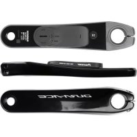
Pedaling Monitor Sensor
SGY-PM900H90
User's Manual
Please read the Important Information for the User in the product box for product warnings and other important safety information.
EN
DE
FR
NL
IT
ES
EN
Table of Contents
Introduction
Features 3
Manuals 3
Compatibility 4
Getting Started
Product Configuration 5
Accessories 5
7
Pairing /Calibration
Pairing with the Cyclocomputer 10
Calibrating the Sensors 12
Getting Ready 12
Calibrating the Zero Point 12
Checking the Zero Point 13
Specifications and support
Troubleshooting 14
Care, Maintenance, and Storage 16
Specifications 17

This product is ANT + ^TM certified. Visit http://www.thisisant.com/directory/ for a list of compatible products and apps.
Features
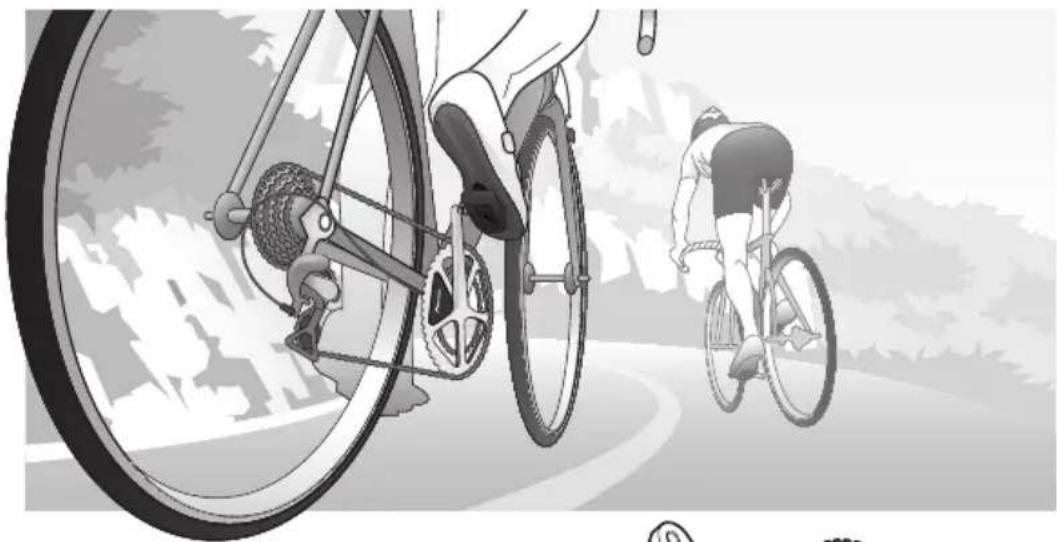
This product is a sensor system that analyzes the pedaling of a bicycle in real time. It calculates the direction and intensity of the force acting on the pedals and calculates pedaling efficiency.
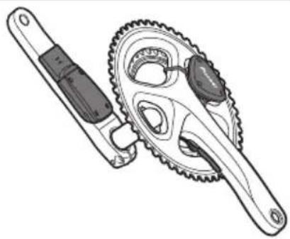
Description of components
- Strain gauge unit: Detects the strain on the crank and calculates the direction and intensity of the force on the crank.
Magnet ring: Used to detect the angle of rotation. - Transmitters: Send information from the strain gauge unit and the magnet ring to the Cyclocomputer.
Switching modes
The switches in the left and right transmitters change the system to the following modes.
- Pedaling mode: Used in combination with the Cyclocomputer SGX-CA900. This mode calculates pedaling efficiency and maximizes the functionality of the product.
Power meter mode: Used with a Cyclocomputer that supports ANT^+^TM
Manuals
The product's manuals consist of this User's Manual, an Installation Manual, and Important Information for the User.
User's Manual:
Explains how to pair the product with the Cyclocomputer and calibrate the sensors.
Installation Manual:
[For American Users] http://www.pioneerelectronics.com
[For Canadian Users] http://www.pioneerelectronics.ca
[For European Users] http://www.pioneer.eu
Explains details about handling methods. The product installation methods (for dealers) are also described as references.
Important Information for the User:
Important Information for the User provides detailed information related to safety.
EN
Compatibility
Crank sets
The product is compatible with the following crank sets.
| Crank sets Remarks | |
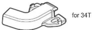
| SHIMANO FC-9000 | • Crank lengths of 165, 167.5, 170, 172.5, 175 mm, crank set of 50-34T, 52-36T, 52-38T, 53-39T are compatible. * |
- Descriptions in this manual are for a 170 mm crank set.
Bottom bracket
The following bottom brackets are compatible.
| Bottom bracket Names of products Remarks | ||
| HOLLOWTECH II, JIS68 | SHIMANO SM-BB7900 and SM-BB6700 * | Uses magnet ring attachment. |
- SHIMANO SM-BB9000 is not compatible.
When you use the following bottom brackets, you need the special optional parts (sold separately).
| Bottom bracket | Names of products Remarks | |
| BB86 Pioneer SGY-BB86 and SGY-BB86C Attaches directly to magnet ring and optional parts (sold separately). | ||
| BB30 Pioneer SGY-BB30 and SGY-BB30C | ||
| PF30 Pioneer SGY-BBPF30 and SGY-BBPF30C | ||
This product is designed to be used for recreational cycling and cycle training applications only and is not designed to withstand racing conditions.
Additionally, this product is designed to be used while cycling on paved roads only. Any damage or malfunction arising from use in racing or riding on dirt roads, cobblestone or any other unpaved roads will not be covered by the manufacturer's limited warranty.
Installing and calibrating the product requires specialized techniques and tools. Ask the shop where you bought the product to install and calibrate it.
Product Configuration
Accessories
This product contains the following parts.
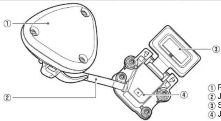
Pedaling monitor sensor (right side)
① Right transmitter
② Junction cable
Strain gauge unit
④ Junction box
Pedaling monitor sensor part (right side) × 1
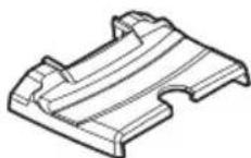
Strain gauge unit cover (right side) x 1


Junction cable guide × 3
Pedaling monitor sensor (left side)
① Left transmitter
② Strain gauge unit

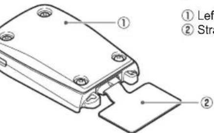
Pedaling monitor sensor part (left side) x 1 Strain gauge unit cover (left side) x 1
Magnet ring
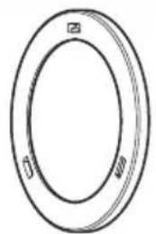
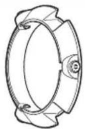
Magnet ring × 2 Magnet ring attachment for Hollowtech II × 2
Accessories

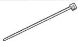
Batteries (CR2032) x 2 Cable ties x 20
Phillips-head screws x 10
User's Manual (this document)
Warranty Card
Important Information for the User
Installing and Removing the Batteries/ Switching Modes
You must install the batteries before using the product. You can change the sensor modes after installing the batteries.
- The product can be used as the ANT+ Power meter with the cyclocomputers of other companies (power meter mode).
To use the product in power meter mode, insert the battery in the right-side part first, and then the left-side part.
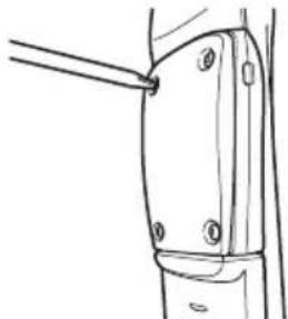
1. Loosen the screws on the transmitter and remove its cover.
Use a philips screwdriver to loosen the screw and remove the cover.
Be careful not to lose the removed screw.
Right transmitter (screws: 3 x)

Left transmitter (screws: 4 x)
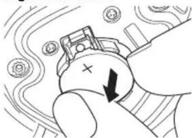
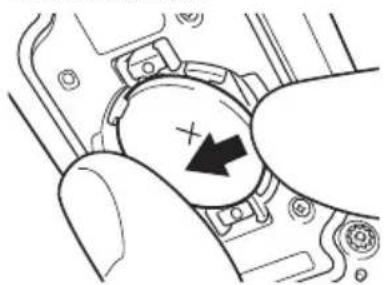
2. Remove the old battery.
Right transmitter
Installing and Removing the Batteries/Switching Modes
Left transmitter
When putting in new batteries for the first time, look at the switches in the battery compartment and make sure the sensor mode is set to the mode you want to use.
The transmitters device numbers are printed on the inside of the covers. Use the device numbers to pair the sensors with the Pioneer Cyclocomputer SGX-CA900. Refer to the Installation Manual for details.
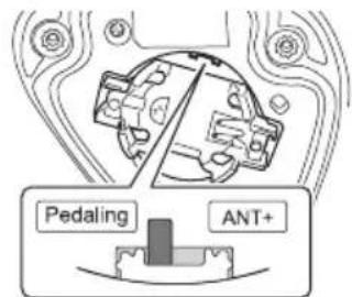
3. Switch the sensor mode.
Change the sensor mode by using the slide switch in the battery compartment while the batteries are removed.
Right transmitter
Left transmitter
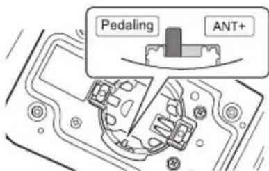
Pedaling: pedaling mode
ANT+: power meter mode
Set the left and right sensors to the same mode.
For use with Pioneer's SGX-CA900, set the sensor mode to "Pedaling".
For use with other cyclocomputer brands, set the sensor mode to "ANT+".
4. Install the new battery (CR2032).
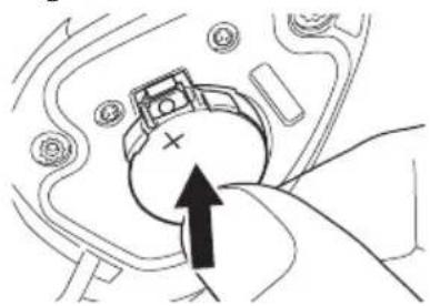
Right transmitter
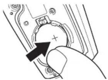
Left transmitter
Do not use batteries other than CR2032.
5. Check the LED display.
Check the following LEDs to make sure that they are working properly.
Power meter mode:
When the batteries are installed, the left and right transmitters start pairing.
When pairing is finished, the LEDs on the left and right transmitters light green for 10 seconds.
Pedaling mode:
When the batteries are installed, the LEDs light green for 10 seconds.
If the LEDs do not light, or only one side lights, install the batteries again. If the LEDs still do not light, the battery may be almost empty. Replace the battery with a new one.
When you use it in power meter mode, insert the right battery and then the left battery and complete pairing the left and right sensors within 5 minutes.
6. Install the cover and tighten the screws to fix it in place.
Use a tool that can measure the torque to tighten the screws.
Tightening torque: 18 cN·m
Tighten the screws on the left - transmitter in a diagonal pattern.
Pairing with the Cyclocomputer
This section describes how to pair the installed SGX-PM900 pedaling monitor sensors on your bicycle to the SGX-CA900 Cyclocomputer.
-
This pairing procedure may be different if you are using a cyclocomputer other than the Pioneer SGX-CA900. Please refer to your cyclocomputer's owner manual for sensor pairing.
-
Check the sensor modes. Check that the right transmitter and left transmitter are in "Pedaling mode
See page 8 to switch the modes. - Tap the [Sensors] icon in the home screen of the SGX-CA900. The sensor list screen opens.
- Rotate the bicycle's crank set one rotation to start the transmitter.
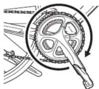
Pair with the Cyclocomputer within 5 minutes after the transmitters are activated.
- Tap [Connect New] in the sensor list screen of the SGX-CA900. The sensor connection menu ope
- Tap [Device Type] and then [Pedaling Monitor R].
For the left transmitter, tap [Pedaling Monitor L]. If multiple sensors are activated, bring the main unit closer to the sensor, or specify the device number to pair the sensor you want to pair. Refer to the User's Guide of the Cyclocomputer SGX-CA900 regarding how to specify a device number to pair a sensor.
- Tap [Search]. The search for the sensor starts. A [Searching. Please wait.] message appears.
7. Check the information about the sensor.
Information about the sensors appears when the sensors are found. Check the following items.
[Device Number]
Make sure that the device number is the same as the device number of the transmitter.
[Error Rate]
Make sure that "OK" is displayed.
| Pedaling Monitor R | |
| Device Number | 129 |
| Manufacturer Number | --- |
| Error Rate | OK |
| Battery | |
If "NG" is displayed in the [Error Rate] area, the information from the sensor is not being received correctly because transmission conditions are bad. Make sure that the sensor you are pairing is activated, then bring the SGX-CA900 closer to the sensor and perform the pairing operation again.
You may not pair with the sensor due to the influence of the 2.4 GHz frequency band. If "NG" is displayed even if the SGX-CA900 is moved closer to the sensor and paired with it, try again someplace where there is no interference from microwaves, radio waves, or wireless equipment.
Pairing of the right transmitter is completed.
Then, pair the left transmitter.
Refer to the User's Guide regarding the device numbers of the transmitters.
If the numbers that are displayed on
[Device Number] are different from the transmitter device numbers, specify the device numbers to pair with the sensor.
Refer to the User's Guide of the Cyclocomputer SGX-CA900
regarding how to specify a device number to pair a sensor.
Calibrating the Sensors
This section describes how to use the Cyclocomputer SGX-CA900 to calibrate the zero point of the pedaling monitor sensor that is installed on the bicycle.
- The right-side pedaling monitor sensor is used as an example in this description. The procedure to calibrate the left side is the same as for the right side.
- Refer to the User's Manual of the Cyclocomputer you are using for calibrating in the power meter mode.
Getting Ready
- Stop the bicycle on a flat safe place.
- Remove the pedal. Remove the pedal to do the calibration.
Calibrating the Zero Point
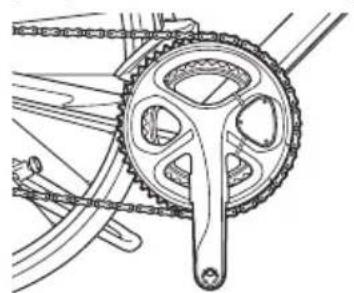
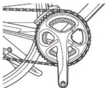
- Position the crank arm so it is perpendicular to the ground.
- Tap the [Sensors] icon in the home screen of the SGX-CA900.
The sensor list screen opens.
-
Tap [Pedaling Monitor R] and then [Calibration (Zero)].
-
Tap [Start Calibration].
The calibration starts. If the calibration is successful, "Success" appears in the [Result] field. If "Failure" is displayed, the sensor may be calibrated in an unstable condition causing the crank to be moving during the calibration. Calibrate again with the crank stopped.
This product has a correction function for the zero point fluctuation caused by varying temperatures. The accuracy of this function improves when the sensor is calibrated in different temperatures.
This function cannot measure correctly if you calibrate or check the sensor before it is acclimated to the outside temperature.
Checking the Zero Point
- Position the crank arm so it is perpendicular to the ground.
Calibration of the right side is finished. Calibrate the left side in the same way.
Re-attach the pedals to your bicycle when both the left and right Zero Point calibrations are completed.
- Tap [Pedaling Monitor R] in the sensor list screen of the SGX-CA900.
- Confirm the value in [Force Preview].
Make sure that the [Tangential Direction Force] and [Radial Direction Force] values are as shown here. Tangential Direction Force: 0 ± 3N Radial Direction Force: 0 ± 3N
| Force Preview | |
| Tangential Direction Force | 0 N |
| Radial Direction Force | 0 N |
Troubleshooting
Refer to the following suggestions if you have any problems installing or using the product.
Refer to the Installation Manual, for more details.
I cannot pair with the Cyclocomputer in the power meter mode or pedaling mode.
| Cause Solution | |
| The battery is almost empty. If the LEDs do not light when you install the battery, the battery is almost empty. Replace the battery with a new one. | (+) or (-) side of the battery is installed in the opposite side. |
| Pedaling monitor sensor mode is wrong. | Change the mode and pair with the Cyclocomputer (see page 8). |
| There are other wireless equipment or microwave ovens near by. | Separate other wireless equipment or microwave ovens. Move the sensor closer to the Cyclocomputer and pair them. |
| Another sensor is paired with the Cyclocomputer. | Separate other sensors more than 10m or specify the device number to pair the Cyclocomputer. Refer to the Installation Manual. |
I cannot pair with the Cyclocomputer in the power meter mode.
| Cause Solution | |
| Pairing between right and left sensors fails. | Make sure that the sensor mode is in the power meter mode. First insert the right battery and then the left battery within 5 minutes. Make sure that left and right sensor LEDs light green. Connect with the Cyclocomputer within 5 minutes after the LEDs illuminate. |
| The device number of the right transmitter is specified. | If you are specifying the device number and searching for the sensor in the power meter mode, specify the device number of the left transmitter. |
Troubleshooting
EN
Zero point calibration fails.
| Cause Solution | |
| The crank is subjected to external force or moving. | Remove the pedal from the crank and calibrate the sensor in still condition (see page 12). |
The Cyclocomputer display is not displaying normally while I am riding.
| Cause Solution | |
| Zero point calibration fails. Calibrate the zero point (see page 12). | |
There is a rattling noise when I am riding.
| Cause Solution | |
| Cable ties that install the sensor or screws are loose. | Retighten the cable ties and screws. |
The magnet ring is rubbing while I am riding.
| Cause Solution | |
| Foreign objects are attached to the magnet ring and rub the transmitter or the junction box. | Clean the transmitter, junction box, and magnet ring. |
Care, Maintenance, and Storage
- Use a soft dry cloth or a cloth that has been dampened and wrung out to wipe dirt from the left and right transmitters, the strain gauge unit covers, the magnet ring, and other accessories.
Do not use benzene, paint thinner, or other volatile chemicals, cleansers, or chemically treated cloths. Doing so could damage the product or cause the paint to peel off. - If you are not going to use the product for a long period of time, remove the batteries.
modns pue
soneee
Specifications
Weight: 73g
Dimensions: Pedaling monitor sensor (right side):
Right transmitter:
60.7mm(W)× 46.9mm(H)× 21.6mm(D)
Junction box, Strain gauge unit cover:
63.3mm(W)× 47.2mm(H)× 9.9mm(D)
Pedaling monitor sensor (left side):
99.4 mm(W) × 48.2 mm(H) × 14.6 mm(D)
Magnet ring:
57.0mm× 3.5mm
Water resistant: This device has a water resistance rating of IPX-6.
Communications method (sensors): ANT+ wireless
Battery: CR2032
Battery operating time: Approximately 200 hours (at moderate temperature)
Operation temperature: -10 to 50^
Accessories: Magnet ring, Magnet ring attachment for Hollowtech II, Batteries (CR2032), Cable ties, Phillips-head screws, User's Manual, Important Information for the User, Warranty Card
- The battery operating time may decrease depending on the usage condition.
- ANT+ is a Wireless Personal Network protocol with very low power requirements using 2.4GHz frequency band.
For more information, visit http://www.thisant.com/
- Specifications and design are subject to change without notice.
- Illustrations used in this manual may be different from actual appearance.
DE
Suny
Inhalt
Einführung
Funktionen 19
Handbucher 19
Kompatibilität 20
Erste Schritte
Pedalsensor (links):
99,4 mm(B) × 48,2 mm(H) × 14,6 mm(T)
Magnetring:
Visit www.pioneer.eu to register your product.
PIONEER ELECTRONICS (USA) INC.
P.O.Box 1540, Long Beach, California, 90801-1540,U.S.A.
TEL: (800) 421-1404
PIONEER ELECTRONICS OF CANADA INC.
340 Ferrier Street, Unit 2, Markham, Ontario, L3R 2Z5, Canada
TEL: 1-877-283-5901
TEL: 905-479-4411
PIONEER EUROPE NV
Haven 1087, Keetberglaan 1, B-9120 Melsele, Belgium/Belgique
TEL: +32 (0)3570 05 11
©2012 PIONEER CORPORATION.
All rights reserved.