
X10W - Meter VDO - Free user manual and instructions
Find the device manual for free X10W VDO in PDF.
| Product type | Bike computer |
| Brand | VDO |
| Model | X10W |
| Dimensions (computer) | 45 × 52 × 16 mm |
| Weight (computer) | 45 g |
| Weight (handlebar mount) | 15 g |
| Weight (sensor) | 20 g |
| Power supply | 3 V battery, type CR2032 |
| Battery life | Approx. 1,200 riding hours (24,000 km) |
| Speed range | 2.5 to 199.5 km/h (for 2155 mm wheel) |
| Distance measurement range | Up to 199,999 km (combined total) |
| Wheel diameter setting range | 100 to 3,998 mm (3.9 to 157.4 inches) |
| Operating temperature | -15 °C to +60 °C |
| Main functions | Current speed, average speed, max speed, trip distance, total distance (2 bikes), trip time, stopwatch, clock, service interval, two bike profiles |
| Display | LCD screen with 4 zones, backlight not specified |
| Mounting | Universal handlebar mount (22-32 mm), wired connection to sensor on fork, magnet on spoke |
| Care and cleaning | Clean with a soft, dry cloth; do not use abrasive products; replace the battery annually |
| Safety | Ensure cable slack; do not overtighten screws; position magnet 1-5 mm from sensor; check proper engagement in the mount |
| Spare parts and repairability | CR2032 battery, handlebar mount, sensor, magnet, zip ties; manufacturer's warranty 5 years on computer, sensor and mount (excluding cables, batteries and mounting materials) |
| Warranty | 5 years from date of purchase (excluding wear parts) |
Frequently Asked Questions - X10W VDO
User questions about X10W VDO
0 question about this device. Answer the ones you know or ask your own.
Ask a new question about this device
Download the instructions for your Meter in PDF format for free! Find your manual X10W - VDO and take your electronic device back in hand. On this page are published all the documents necessary for the use of your device. X10W by VDO.
USER MANUAL X10W VDO
D-76865 Rohrbach (Germany)
| Preface | Table of contents | |
| Congratulations With your selection of a VDO computer you have opted for a technically very high quality appliance. In order to fully benefit from the potential of the computer, we recommend that you carefully read this manual. It contains all operating instructions and many other useful tips. We hope you enjoy cycling with your vDO bike computer. Cycle Parts GmbH | 1. Display 22 2. Operation 24 3. Information functions 25 4. Installation 26 4.1 Fitting the sensor, magnet and handlebar holder 26 4.2 Installing the battery in the computer 27 4.3 Placing the computer into the handlebar holder 27 | 5. Basic settings 28 5.1 Setting the language 28 5.2 Setting and measuring the wheel size 28 5.2.1 Select from tyre table 28 5.2.2 Setting using wheel circumference 30 5.3 Setting the CLOCK 31 5.4 Setting the total kilometres 32 5.5 Switch from Bike1 to Bike2 32 5.6 Service interval display 33 5.7 Sleep mode 34 5.8 Reset functions 35 |
| Pack contents | ||
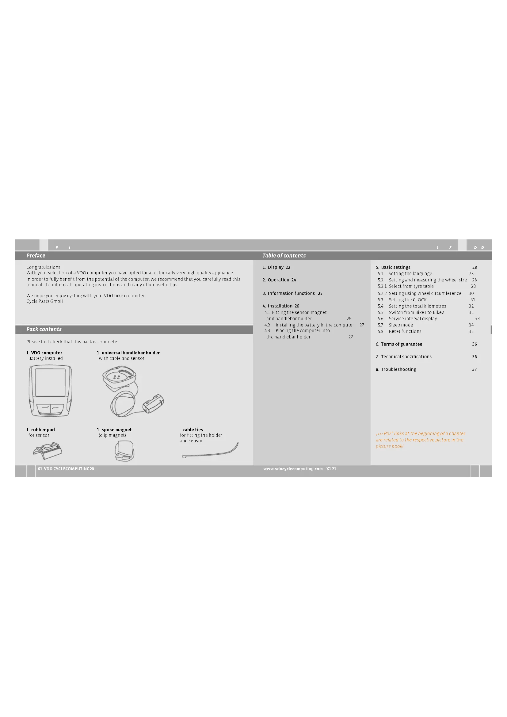
| Please first check that this pack is complete: 1 VDO computer Battery installed | 1 universal handlebar holder with cable and sensor | 6. Terms of guarantee 36 7. Technical specifications 36 8. Troubleshooting 37 |
| 1 rubber pad for sensor | 1 spoke magnet (clip magnet) | →P02* links at the beginning of a chapter are related to the respective picture in the picture book! |
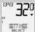
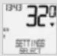
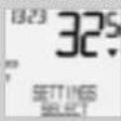
1. Display
The display can be divided into 4 sections:
Section 1 always shows the current time
You will also find indicator elements on the display
You can find the description of the individual indicators on the right hand side.
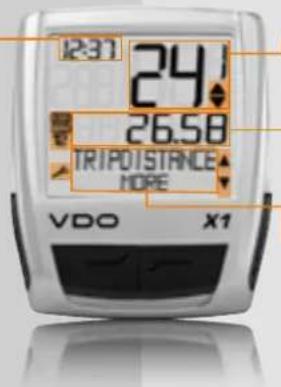
Section 2 shows the current speed
Section 3 shows the value of the display function? Information that you selected.
Section 4
shows the description of the selected function in the top line (info line). The second line (menu line) shows,
whether there is more information ^ 念 MORE
whether there is another selection option. SELECT
Service indicator
shows that your bike should go for a service. You can set the service interval individually for bike 1 and bike 2
Indicator bike 1/bike 2
The computer can work with two different settings for 2 bikes. The indicator shows which of the two bikes you have chosen to use. The total distances are accordingly counted and stored separately for bike 2 and bike 2
Measurement unit (KMH or MPH)
The computer can display both KHW and MPH Distances are shown in kilometres or miles accordingly. The indicator shows the selected measurement unit.

Speed difference indicator (current) speed (average)
The computer compares the current speed with the average speed. The indicator shows whether the current speed is higher than the average (+1KMH)
below the average [-1 KMI] or matches the average [tolerance +/- 1 KMI]
Menu prompt indicator
When a submenu has been accessed, these indicators flash and show that there are other selection options or that the computer is waiting for an entry (selling mode).
2. Operation
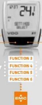
To make your computer easy to use, we have developed the EMIC Easy Menu Control System.
The EMC makes your computer easier to operate by means of a full text menu guidance.
as is used on most mobile phones.
Menu indicators on the display flash to show that there are other selection options.
In function mode and setting mode, the computer is operated using the 4 buttons.
C=CLEARDOWN
M-MENU
10
C-CLEAR
In function mode:
Jump back a menu level from
the submnu.
In setting mode:
Jump back to function mode
Corrected
jump back a digit
=DOWN
In function mode:
Scroll downwards within the functions.
In setting mode:
- Scroll downwards within the setting modes.
Decrease a digit.
M = MENU
In function mode:
Access available submert
假 confirm selection
You can recognise a submenu by
the flashing menu indicators
In setting mode:
Select a setting
念 Confirm a setting
Confirm a selection made.
=UP
In function mode:
Scroll upwards within
the functions.
In setting mode:
Scroll upwards within
the setting modes
Increase a dig.
3. Information functions in function mode
TRIPDISTANCE
Shows the distance of the current trip since the last reset. Maximum value 999.99 km.
If the maximum value is exceeded, the counter starts again at zero. At the same time the values for ride time and average speed are set back to zero.
TRIPDISTANCE/MORE
MORE shows that there is a menu for the main menu TRIPDISTANCE. You open the menu with the button. In the menu you will find:
Total kilometres BIKE 1ODO BIKE 1 up to a maximum of 99,999 km.
Total kilometres BIKE 2 ODO BIKE 2 up to a maximum of 99,999 km.
Total kilometres for Bike 1 + Bike 2 ODO TOTAL up to a maximum of 139,959 km.
You leave the submenu by pressing again.
RIDE TIME
Shows the ride time of the current day's trip since the last reset. Maximum 23:59:59 HMMSS If the maximum value is exceeded, the ride measurement starts again at zero. At the same time the day's trip distance and average speed are set back to zero.
AVG SPEED
Shows the average speed, calculated from the day's tripdistance and ride time, since the last reset Accuracy 2 decimal places.
The average speed is recalculated in the day's trip-distance or ride time exceeds the maximum value.
MAX SPEED
Shows the maximum speed on the current trip since the last reset. Accuracy: 2 decimal places.
4 Installation
4.1 Fitting the sensor, magnet and handlebar holder >> POI
When fitting to suspension forks, it is essential to bear in mind the spring deflection of the forks. The cable requires an appropriate amount of play.
ATTENTION: Risk of broken cable
Step3 Place the rubber pad under the sensor. Fit the sensor on the same side of the fork where you later want to fit the computer to the handlebars (right or left) using the cable ties supplied (loose at first, do not pull tight just yet). Depending on the room available, the sensor can be fitted at the front of the fork, inner side of the fork or backside of the forks.
Step 2 Place spoke magnet around an outer spoke. The silver middle of the magnet points towards the sensor. Align the magnet to the sensor mark with a gap of about 1 - 5mm
Step 3 Align sensor and magnet for good and fasten in place: Pull cable ties light and push magnet in firmly.
Step4 Install cable from sensor already fitted along brake cable to the handlebars (fasten with cable ties supplied) Ideally: Coil sensor cable up around the brake cable.
Step 5 Decide whether fitting to handlebar or stem and turn the base of the handlebar holder by 90^ accordingly. To do so, undo the screws in the holder, take out the foot and turn it 90^ , insert and tighten the screws again.
ATTENTION: Do not over lightens screws.
Step 6 Guide the cable ties through the slot in the handlebar holder, place around the handle bars or the stem and pull (do not pull tight just yet).
Step7 If fitting to handlebars. Align computer angle to achieve optimum readability. Now pull cable ties tight. Snip off protruding ends with clippers.
4.2 Installing the battery in the computer P03
Your VDO computer is supplied with a 3V battery (type 2332). The battery is already installed
when supplied. To change the battery, proceed as follows:
step 1 Place the battery in the computer casing with the terminal facing up.
Step 2 Make sure that the battery does not get wedged.
step 3 Take care that the rubber seal lies flat on the battery compartment lid.
Step 4 Insert the battery compartment lid into the opening and turn it with a coin to the right as far as it will go (approx.1/3 turn).
TIP for changing battery: VDO recommends changing the battery once a year. Buy a new battery in good time to ensure the function works perfectly. When the battery is changed, all basic computer settings are reset to factory settings. Before removing the old battery, it is therefore essential to note down the wheel sizes entered and the total kilometres cycled so far for your bike 2 and bike 2. Program these in again after inserting the new battery.
4.4 Placing the computer into the handlebar holder >> P04
The VDO twist- click system fastens the computer securely with the handlebar holder.
Step 1 Place computer into the holder in 10 a'clock position
Step 2 Twist computer to the right to 12 o'clock position and click into the holder system.
Step 3 To take the computer out, twist to the left (co not push or pull).
How to remember Rigid to the Right, Loose to the Left
5. Basic settings
5.1 Setting the language
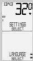
Using the buttons, go to SETTINGS/SELECT.
connrwnn
you back to function model.
you back to function mode
LALNGUAGESELECT
Confirm with

LALANGUAGE ENGLISH.
Confirm with
ENGLISH SELECT OKP Confirm with
LANGUAGE SELECT DONE. The computer automatically returns to the start menu SETTINGS/SELECT.
5.2 Setting and measuring the wheel size
You must set the wheel size (wheel) roll circumference of your bike so that your VDO computer can measure correctly.
5.2.1 Setting using tyre table
The common types of tyres are listed in the tyre table. If your tyre type is not listed, we recommend entering the wheel size manually.
There are 2 ways of doing this
The values given in the table are approximate values. These values differ according to brand, tyre height and tyre profile. This can consequently also lead to discrepancies in the distance measured and the speed shown.
mm-value inch-value
| 16 x 1,75 1272 | 50,1 | |
| 20 x 1,75 | 1590 | 62,6 |
| 24 x 1% | 1948 | 78,7 |
| 24 x 1,75 | 1907 | 75,1 |
| 26 x 1 | 1973 | 77,7 |
| 26 x 1,5 | 2026 | 79,8 |
| 26 x 1,6 | 2051 | 80,7 |
| 26 x 1,75 | 2070 | 81,5 |
| 26 x 1,9 | 2089 | 82,2 |
| 26 x 2,00 | 2114 | 83,2 |
| 26 x 2,125 | 2133 | 84,0 |
| 26 x 1% | 2105 | 83,9 |
| 26 x % | 1954 | 76,9 |
| 27 x 1% | 2199 | 88,6 |
| 28 x 1,5 | 2224 | 87,6 |
| 28 x 1,75 | 2268 | 89,3 |
| 28 x 1% | 2265 | 89,2 |
| 28 x 1% | 2205 | 86,8 |
| 30-622 | 2149 | 84,6 |
| 32-622 | 2174 | 85,6 |
| 37-622 | 2205 | 86,8 |
| 40-622 | 2224 | 87,6 |
How to set the tyre size by selecting the tyre:
Using go to SETTINGS/ SELECT Confirm with. You are now in setting mode (pressing for 3 seconds gets you back to function mode).
IFD
续

using up/down go to
WHEELSIZE/SET
Confirm with

MEASUREMENT/KMH
Confirm with or
change to MPH

WHEELSIZE/BIKE1(use to
go to setting for bike 2)
Confirm with

WHEELSIZE/ TYRE SELECT
Confirm with X

TYRE SELECT/SELECT
Now select your tyres using
Confirm with
The confirmation question appears "Tyresize? SELECT OK? When the displayed tyre size matches the one you want, confirm with
The display confirms WHEELSIZE/SET DONE
Automatic return to SETTINGS/SELECT
5.2.2 Setting using wheel circumference POS
Measuring wheel roll circumferences:
To enter the wheel size manually, you must first measure the wheel roll circumference on your bike
step 1 Precisely align valve on the front wheel vertically to the ground.
Step 2 Mark this spot on the ground with a line (e.g. chalk).
step3 Push the bike forwards one turn of the wheel until the valve is vertical to the ground again
Step4 Also mark this spot on the ground.
Step 5 Measure the distance between the two marks. That is your wheel circumference (roll circumference):
Step 6 Enter the wheel circumference measured in this way into your VDO computer.
ATTENTION: If you have selected KMN display, you must enter the wheel circumference in mm (If MPJ display is selected, enter the wheel circumference in inches).
How to set the wheel size manually:
Using go to SETTNGS/ SELECT. Confirm with You are now in setting mode (pressing for 3 seconds gets you back to function mode)

Using Foto WHEELSIZE/ SET Confirm with:

MEASUREMENT/KMH Confirm with 0 or 10 change to MPH

WHEELSIZE/BIKE 1(use to go to setting forbike 2 Confirm with
Using goTo WHEEL SIZE/MANUAL SET Confirm with

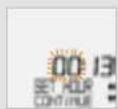
BIKE 1...SET SIZE/CONTINUE Now set the wheel roll circum ference measured using Confirm the entry with
BIKE1/SETOK? Confirm with M
The display confirms: WHEELSIZE/SET DONE.
Automatic return to SETTINGS/SELECT
ATTENTION: The factory settings for bike 1 = 2155 mm and for bike 2 = 2000 mm. If you do not enter any wheel sizes, the computer works with these factory settings. The values measured in this way for speed, distance etc. can differ widely from the actual values.
5.3 Setting the clock
How to set the clock:
Using -go to SETTINGS/ SELECT Confirm with.. You are now in setting mode (pressing for 3 seconds gets you back to function mode)

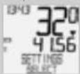
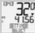
Using 18 to CLOCK/SET Confirm with D
CLOCK/24-H-MODE (you can switch to 12-H mode using Confirm with M.
CLOCK...SET HOUR/CONTINUE Set the hours using.. Confirm the hour setting with

CLOCK. SET MINUTES/ CONTINUE. Set the minutes using Confirm the minutes setting with
CLOCK/SET OK? Confirm with
The display confirms CLOCK/SET DONE Automatic return to SETTINGS/SELECT.
5.4 Setting the total kilometres
You can program the values on the distance counter at any time (e.g. at the end of a season).
Using go to SETTINGS/ SELECT Confirm with You are now in setting mode (pressing for 3 seconds gets you back to function mode).
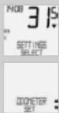
Using Dotoo ODOMETER/ SET Confirm with

ODOMETER/ODO BIKE 1 (use to go to setting for BIKE2). Confirm with ODO BIKE1. SET DISTANCE CONTINUE.

You can set the flashing digits using A To access the next digit, confirm with M. Repeat the steps until the last digit on the right is flashing Confirm with M.
ODO BIKE I/SET OK? Confirm with
The display confirms ODD BIKI /SET DONE Automatic return to SETTINGS/SELECT.
5.5 Switch from Bike 1 to Bike 2
Your VDO computer can be used on two bikes. If you switch from bike 1 to bike 2, you must set the computer to the bike being used before the ride.
Using Be to SETTINGS/ SELECT Confirm with You are now in setting mode (pressing for 3 seconds gets you back to function mode).

Using 50 to BIKE/SELECT Confirm with M.
BIKE1:use1 switch to bike2. Confirm with
BIKE1/SELECT OK? Confirm with
The display confirms BIKE/SELECT DONE Automatic return to SETTINGS/SELECT
The selected bike 1 or 2) is shown on the display bottom left.
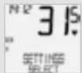
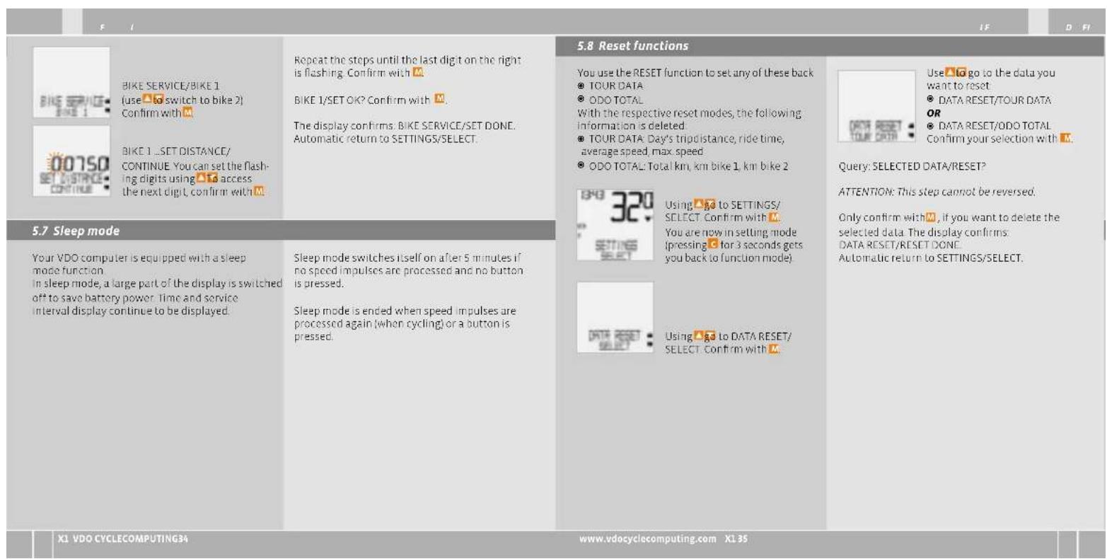
5.6 Service interval display
The VDO service interval display reminds you to have your bike checked in the workshop. You can switch the service interval ON or OFF. You can set separate service intervals for 2 bikes. When the set service interval distance has been reached:
The Symbol Flashes on the display. The information line displays PIKE SERVICE/PIKE 1
You should now either carry out the recommended bike check yourself or have the bike checked by your dealer. Press any button. The text BIKE SERVICE disappears again. After another 50 km the -also disappears. You can also switch off the flashing symbol. To do so, enter the service interval again
ATTENTION, important note: When switching from bike 1 to 2 or vice versa, the data for days tripdistance, ride time, average speed and max speed for the last trip are set to zero.
How to set the service interval:
Using go to SETTINGS/ SELECT Confirm with. You are now in setting mode (pressing for 3 seconds gets you back to function mode).

Using to BIKE SERVICE/ SET Confirm with M.

BIKE SERVICE/ON (switch to OFF using a Confirm with
| 6. Terms of guarantee | ||||
| VDO Cycle Parts grants a guarantee of 5 years from the date of purchase for your VDO computer. The guarantee covers material and processing defects on the computer itself, on the sensor/transmitter and on the handlebar holder. Cables and batteries as well as assembly materials are excluded from the guarantee. The guarantee is only valid if the parts concerned have not been opened (exception: battery compartment on the computer), no force has been used and there is no sign of wilful damage. Please take care to keep the receipt as it must be presented in the event of a complaint. If the complaint is justified, you will receive a comparable replacement appliance from us. You are not entitled to an identical replacement model if the model in question is no longer in production due to a change of model | Please contact the dealer from whom you purchased the device for all complaints and guarantee claims Or send your complaint directly to: | Total KM 1 and 2 measurement range: up to 99,999 km or mi Total kilometers measurement range: up to 199,999 km or mi | Wheel circumference setting range from 100 mm to 3999 mm (8.9 to 1574 inches) | |
| Cycle Parts GmbH Große Animühle 33 D-76865 Rohrbach (Germany) | ||||
| We would be pleased to answer any technical questions you might have at the following hotline number: +49 (0) 63 49 - 96 35 - 10. | Here you can find a list of possible faults, their causes and what you can do about them: | |||
| Additional technical information is available at: www vdocyclecomputing.com | ||||
| We reserve the right to make technical changes in the course of further development. | No speed display Distance from sensor to magnet too big | Correct position of sensor and magnet | ||
| No speed display Computer not properly clicked in the handlbrar holder | Place computer head in the handlebar holder, twist until it clicks | |||
| 7. Technical specifications | ||||
| Computer: approx. 45 x 52 x 16 mm, weight: approx. 45 g Handlebar holder: weight: approx. 15 g Sensor: weight approx. 20 g Computer battery: 3V, type 2032 Battery life-span: 1200 cycling hours, approx. 24,000 km (15,000 M) | Working temperature of the display: -15 °C to -60 °C Speed range: for wheel size 2155 mm, min 2.5 km/h, max 199.5 km/h Ride time measurement range: up to 23:59:59 HH:MM:SS Day's trip counter measurement range: up to 999.99 km or mi | No speed display Wheel circumference is not correctly set or is at zero | Set wheel circumference | |
| Display becomes weak | Battery dead | Check battery, replace if nec. | ||
| Display becomes weak | Temperatures under S' make the display sluggish | At normal temperatures the display will work normally again | ||
| Display becomes weak | Temperatures under S' make the display sluggish | At normal temperatures the display will work normally again | ||
DGB
Preface
Merci
© Confirmance selection
oue raynrs 20 mode of tax
(1)
toommernr
Vouysoustreewzolsern made
wou wou trovez aorrs en mcue
D-76865 Rohrbach (Germany)
jusq'23:59:59 HHMMSS
m = 311
7
R
B
1
.
0
1
72
72
73
D-76855 Rohrbach (Germany)
Correct Disposal of This Product
Waste Electrical & Electronic Equipment
(Aplicable in the European Union and other European countries with separate collection systems). This marking shown on the product or its literature, indicates that it should not be disposed with other household wastes at the end of its working life. To prevent possible harm to the environment or human health from uncontrolled waste disposal, please separate this from other types of wastes and recycle it responsibly to promote the sustainable reuse of material resources. Household users should contact either the retailer where they purchased this product, or their local government office, for details at where and how they can take this item for environmentally safe recycling. Business users should contact their supplier and check the terms and conditions of the purchase contract. This product should not be mixed with other commercial wastes for disposal.


- Display
- Section 4
- Service indicator
- Indicator bike 1/bike 2
- Measurement unit (KMH or MPH)
- Speed difference indicator (current) speed (average)
- Menu prompt indicator
- Operation
- C-CLEAR
- =DOWN
- M = MENU
- =UP
- Information functions in function mode
- TRIPDISTANCE
- TRIPDISTANCE/MORE
- RIDE TIME
- AVG SPEED
- MAX SPEED
- Installation
- Fitting the sensor, magnet and handlebar holder >> POI
- Installing the battery in the computer P03
- Placing the computer into the handlebar holder >> P04
- Basic settings
- Setting the language
- Setting and measuring the wheel size
- Setting using tyre table
- How to set the tyre size by selecting the tyre:
- Setting using wheel circumference POS
- Measuring wheel roll circumferences:
- Setting the clock
- Setting the total kilometres
- Switch from Bike 1 to Bike 2
- BIKE1/SELECT OK? Confirm with
- Service interval display
- How to set the service interval:
- Preface
- Merci
- Correct Disposal of This Product
Brand : VDO
Model : X10W
Category : Meter