USER MANUAL SMT190DN SAMSUNG
19" LCD Built in 8CH DVR SMT-190Dx
User Manual
IMPORTANT SAFETY INSTRUCTIONS

CAUTION
RISK OF ELECTRIC SHOCK DO NOT OPEN

CAUTION: TO REDUCE THE RISK OF ELECTRIC SHOCK, DO NOT REMOVE COVER (OR BACK). NO USER SERVICEABLE PARTS INSIDE. REFER SERVICING TO QUALIFIED SERVICE PERSONNEL.
Graphic Symbol Explanation
The lightning flash with arrowhead symbol within an equilateral triangle is intended to alert the user to the presence of uninsulated 'dangerous-voltage' within the product's enclosure that may be of sufficient magnitude to constitute a risk of electric shock to persons.

The exclamation point within an equilateral triangle is intended to alert the user to the presence of important operating and maintenance (servicing) instructions in the literature accompanying the appliance.

Warning - To Prevent Fire or Shock Hazard, Do Not Expose This Monitor To Rain or Moisture.
1. Read Instructions :
All the safety and operating instructions should be read before the appliance is operated.
2. Retain Instructions :
The safety and operating instructions should be retained for future reference.
3. HeedWarnings:
All warnings on the monitor and in the operating instructions should be adhered to.
4. Follow Instructions :
All operating and user instructions should be followed.
5. Cleaning :
Unplug this monitor from the wall outlet before cleaning. Do not use liquid cleaners or aerosol cleaners. Use a damp cloth for cleaning. Exception. A monitor that is meant for uninterrupted service and that for some specific reason, such as the possibility of the loss of an authorization code for a CATV converter, is not intended to be unplugged by the user for cleaning or any other purpose may exclude the reference to unplugging the monitor in the cleaning description otherwise required in Item 5.
6. Attachments :
Do not use attachments not recommended by Samsung as they may cause hazards.
7. Water and Moisture :
Do not use this monitor near water for example, near a bathtub, wash bowl, kitchen sink or laun dry tub, in a wet basement or near a swimming pool and the like wet basement or near a swimming pool and the like.
8. Accessories :
Do not place this monitor on an unstable cart, stand, tripod, bracket or table. The monitor may fall, causing serious injury to a child or adult and serious damage to the appliance. Use only with a cart, stand, tripod. bracket or table recommended by Samsung, or sold with the monitor. Any mounting of the monitor should follow Samsung's instructions and should use a mounting accessory recommended by Samsung.
9. Ventilation :
Slots and openings in the cabinet are provided for ventilation and to ensure reliable operation of the monitor and to protect it from overheating and these openings should never be blocked by placing the monitor on a bed, sofa, rug or other similar surface. This monitor should never be placed near or over a radiator or heat register. This monitor should not be placed in a built-in installation such as a bookcase or rack unless proper ventilation is provided or Samsung's instructions have been adhered to.
USER'S MANUAL
10.Installation :
Do not install near any heat sources such as radiators, heat registers, stoves, or other appliances (including amplifiers) that produce heat.
11.Power Sources :
This monitor should be operated only from the type of power source indicated on the making label. If you are not sure of the type of power supply to your installation site, consult your Samsung dealer or local power company.
12. Grounding or Polarization :
For monitors equipped with a 3-wire grounding-type plug having a third(grounding) pin. This plug will only fit into a grounding type power outlet. This is a safety feature. If you are unable to insert the plug into the outlet, contact your electrician to replace your obsolete outlet. Do not defeat the safety purpose of the grounding-type plug.
13.Power :
Cord Protection-Power supply cords should be routed so that they are not likely to be walked on or pinched by items placed upon or against them, paying particular attention to cords at plugs, convenience receptacles, and the point where they exit from the monitor.
14.Lightning :
For added protection for this monitor during a lightning storm or when it is left unattended and unused for long periods of time, unplug it from the wall outlet and disconnect the cable system. This will prevent damage to the monitor due to lightning and power-line surges.
15.Overloading :
Do not overload wall outlets and extension cords as this can result in a risk of fire of electric shock.
16.Object and liquid Entry :
Never push objects of any kind into this monitor through openings as they may touch dangerous voltage points or short-out parts that could result in a fire or electric shock. Never spill liquid of any kind on the monitor.
17.Servicing :
Do not attempt to service this monitor yourself as opening or removing cover may expose you to dangerous voltage or other hazards. Refer all servicing to qualified service personnel.
18.Damage Requiring Service :
Unplug this monitor from the wall outlet and refer servicing to qualified service personnel under the following conditions.
a. When the power-supply cord or plug is damaged. b. If liquid has been spilled or objects have fallen into the monitor.
c. If the monitor has been exposed to rain or water.
d. If the monitor does not operate normally by following the operating instructions. Adjust only those controls that are covered by the operating instructions as an improper adjustment of other controls may result in damage and require extensive work by a qualified technician to restore the monitor to its normal operation.
e. If the monitor has been dropped or the cabinet has been damaged.
f. When the monitor exhibits a distinct change in performance this indicates a need for service.
19.Replacement Parts :
When replacement parts are required, be sure the service technician has used replacement parts specified by Samsung or have the same characteristics as the original parts. Unauthorized substitutions may result in fire, electric shock or other hazards.
20.Safety Check :
Upon completion of any service or repairs to this monitor, ask the service technician to preform safety checks to determine that the monitor is in proper operating condition.
Contents
IMPORTANT SAFETY INSTRUCTIONS
Chapter 1: Overview
1-1) Product Introduction 6
1-2)Features 6
Chapter 2: System Components and Installation
2-1) Requirements for installation and safety 7
2-2) System Components 8
2-3) Standard Camea composition and installation method 9
2-4) Night Vision Camera 10
2-5) External terminal connecting method for Camera and Monitor ....12
Chapter 3: Identifying the parts and their features
3-1) Monitor 14
■Front. 14
Rear. 16
Remote Controller 17
Chapter 4: Basic Use
4-1) Power On 18
4-2) Recognition of Input video signal 18
4-3) Basic screen 18
Menu Configuration 19
5-1) CLOCK/DISPLAY SETUP 19
5-2) RECORD MODE SETUP 20
5-3) TITLE SETUP 20
5-4)DWELL TIME SETUP 21
5-5)ALARMSETUP 21
5-6) EVENT RECORD MODE 21
5-7) TIMER RECORD MODE 22
5-8)SYSTEM SETUP 23
5-9) NETWORK SETUP 24
5-10) ARCHIVE SETUP 27
(5-11) SYSTEM INFORMATION 27
Chapter 6: Recording
7-1) SEARCH MENU 28
7-2) DATE TIME SEARCH 28
7-3) RECORD EVENT SEARCH 29
7-4) ALARM EVENT SEARCH 29
7-5) LOSS EVENT LIST 29
7-6) POWER EVENT LIST 29
7-7) BASIC PLAYBACK 29
Chapter 8 : Remote Viewer Connection
8-1) SMT-190DN basic settings 30
8-2)“LIVE" MENU 31
8-3)Admin Menu 35
Chapter 9 : Functions
9-1) FREEZE KEY 43
9-2) ZOOM MODE DISPLAY 43
(9-3)PIP MODE DISPLAY 43
9-4) SINGLE SCREEN DISPLAY 44
9-5)QUAD MODE DISPLAY 44
(9-6) AUTOSEQUENTIAL DISPLAY MODE 45
9-7) LIVE/PB/TRIPLEX KEY 45
No Signal Display 46
OSD Menu Selection 46
A. Input Menu 46
B.Picture Menu 48
C. Sound Menu 51
D. Setup Menu 52
Chapter 11 : Product specification
Chapter 12: Appendix
IP RouterSetupGuide 66
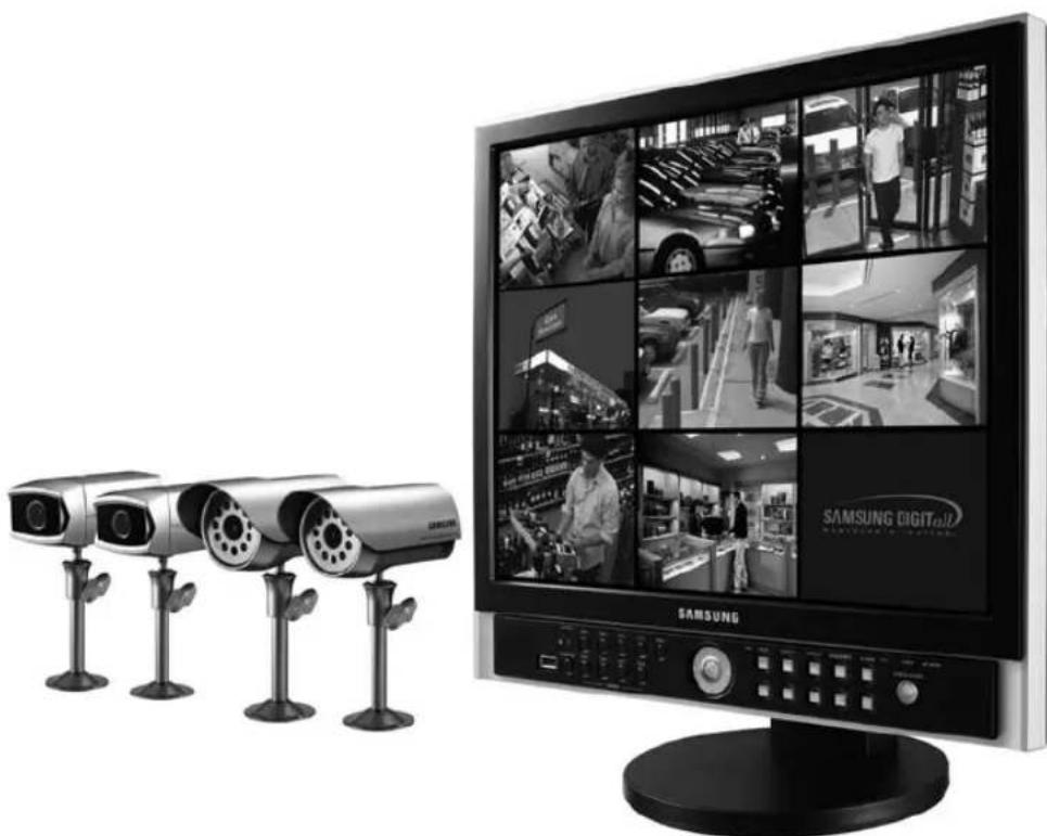
Chapter 1 : Overview
1-1) Product Introduction
SMT-190DN is a Digital Video Recorder (DVR) that records video and audio data from 8 cameras to its internal HDD and plays back simultaneously. It saves video data from each channel as a separate MPEG-4 file. It uses G-723 compression method to save video data. It can transfer video and audio data to external device through a network, and monitor the transferring from a remote site.
- DVR refers to a device that uses a hard disk (HDD) to save video and audio rather than video tapes that existing Video Cassette Recorders (VCR) use. With DVR, it is easy to playback or search videos that have been saved. Editing and transferring video images are also convenient as they are saved as digital signals. It uses standard specifications of video and audio compression to compress, save, and , and transfer video. You may search according to time, date, camera, and event. Real time remote monitoring is available, and so are search and archive.
1-2) Features
- 3 modes of recorded image quality adjustment
-HIGH,NORMAL,LOW
- Various adjustments for the number of recorded fields per second
- NTSC : 1 IPS ~ MAX 30 IPS
- PAL:1IPS\~MAX25IPS
- Recording of video image up to the preset time before Event (Alarm) activates (Pre-Alarm)
-OFF,5SEC
- Recording during playback (DUPLEX)
- Recording/Playing back of the selected channel
- Timer recording
Alarm recording
- Various playback speeds available
- Convenient search feature
-
Date Time Search, Event (Record, Alarm) Search
-
Pause feature for video currently being monitored (FREEZE)
- 2X ZOOM feature for videos being monitored
-
Several types of screen split modes
-
Full Screen Display, 4 Split Display, 9 Split Display, Sequence Display, PIP Display
-
Remote monitoring and controlling through Network
Chapter 2: System Components and Installation
2-1) Requirements for installation and safety
This section describes the requirements for safe installation and use.
Install the product on a flat table or in a rack. It should be used only when level and should not be used when standing vertically or at an acute angle.
The location in which the main system is installed and the configuration of the room are very important for proper operation of the system.
When the products are installed too closely together or the location is poorly ventilated, the system may not operate properly and maintenance of the system may be difficult. Sufficiently circulate the air within the system operating room and tightly fasten the cover of the main system to prevent malfunction and reduce system downs due to environmental causes. There are high voltage parts inside. Do not open the cover.
Install the product in a place that meets the following environmental conditions. Be sure to maintain the system under the temperatures and humidity conditions given below:
- Operating temperature: 0^ 40^ ( 32^ 104^ )
- Storage temperature: -20^ 60^ (-4^ 140^)
- Operating humidity: 20% 85% RH
- Storage humidity: 20% 95% RH
- Input voltage: AC 100V ~ 240V
- Power usage : less than 85 Watts
Frequency:60Hz/50Hz
Caution
When operating the product, the fluctuation of input voltage must be within 10% of the rated voltage and the external power outlet must be grounded, otherwise, it may cause electric shock or malfunction of the product. Do not connect heat-generating appliances such as a hair dryer, iron or refrigerator to the same power outlet in which the product is plugged, otherwise it may cause a fire or malfunction of the product. The use of an Automatic Voltage Regulator (AVR) is highly recommended to ensure that stable power is supplied.
Caution
SMT-190DN is fitted with a 250GB HDD and this HDD can change with a new one.
Our Company guarantees only SEAGATE 250GB ST3250820ACE as HDD.
HgLAMP(S) INSIDE THIS PRODUCT CONTAIN MERCURY AND MUST BE RECYCLED OR DISPOSED OF ACCRDING TO LOCAL, STATE OR DISPOSED OF OF ACCRDING TO LOCAL, STATE OR FEDERAL LAWS.
For details see lamprecycle.org, eiag.org, or call 1-800-Samsung
2-2) System Components
The system consists of the following:
| SMT-190DN(P) | SMT-190DK(P) |
| Camera | | Weather Resistant Camera
SOC-C120(P) : 2ea | None |
| Cable | | Night Vision camera
SOC-N120(P) : 2ea |
| Camera Cable
60ft : 4ea |
| Common Use | Camera
Bracket
4ea) | Sensor
Connector
(4ea) | None |
| Monitor 19"
LCD Built in
8CH DVR | Remote
& Batteries
(2 X AAA) | Installation
manual | | Instruction
CD |
| Power
Cable | Ethernet
Cable | Cloth-
Clean | | Quick start
guide |
| ITEM MODEL DESCRIPTION NOTE | | |
| MONITOR SMT-190DN 19" LCD Bulit in 8CH DVR - | | |
| CAMERA | SOC-C120(P) | Weather Resistant Camera - | |
| SOC-N120(P) | Night Vision Camera | |
| CAMERA BRACKET SBR-110S Stand Type Bracket Tapping Screw 6 | | |
| CAMERA CABLE MCB-60 6Pin Shield Cable 60ft (1ft = 0.3048m) | | |
| INSTALLATION MANUAL - | - | - | |
| POWER CORD | - | - | - |
| SENSOR CONNECTOR | - | - | - |
| ETHERNET CABLE | - | - | 6ft (1ft = 0.3048m) |
| REMOTE CONTROLLER - | - | - | |
| Video System | Weather Resistant Camera | Night Vision Camera | Camera Cable |
| SMT-190DN | NTSC | SOC-C120 : 2EA | SOC-N120 : 2EA | 60ft : 4EA |
| SMT-190DN/XAC | NTSC | SOC-C120 : 2EA | SOC-N120 : 2EA | 60ft : 4EA |
| SMT-190DP/GBR | PAL | SOC-C120P : 2EA | SOC-N120P : 2EA | 60ft : 4EA |
| SMT-190DP | PAL | SOC-C120P : 2EA | SOC-N120P : 2EA | 60ft : 4EA |
| SMT-190DKP | PAL | - | -- | |
| SMT-190DK/KJPN | NTSC | - | - | |
| SMT-190DK | NTSC | - | - | |
| SMT-190DN/JPN | NTSC | SOC-C120 : 2EA | SOC-N120 : 2EA | 60ft : 4EA |
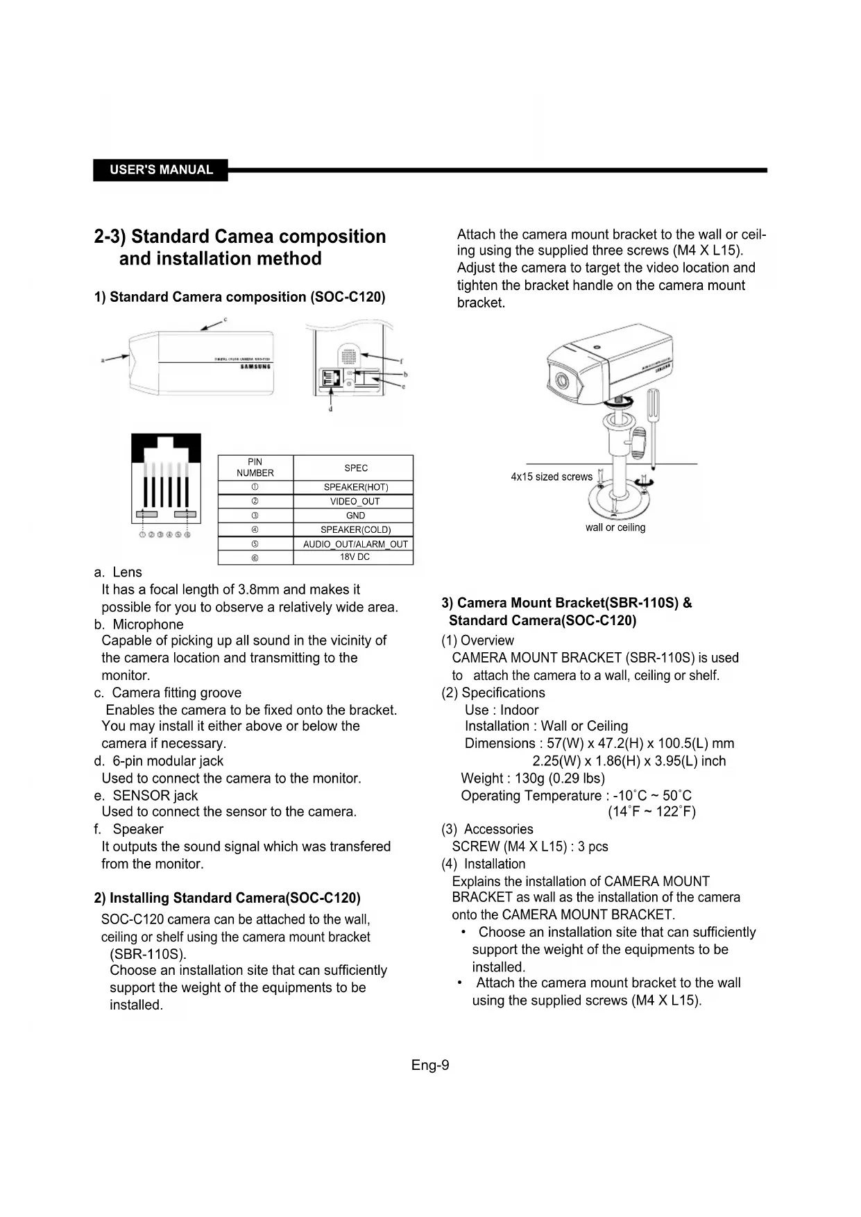
2-3) Standard Camea composition and installation method
1) Standard Camera composition (SOC-C120)

12 ④ 5
| PIN
NUMBER | SPEC |
| ① | SPEAKER(HOT) |
| ② | VIDEO_OUT |
| ③ | GND |
| ④ | SPEAKER(COLD) |
| ⑤ | AUDIO_OUT/ALARM_OUT |
| ⑥ | 18V DC |
a. Lens
It has a focal length of 3.8mm and makes it possible for you to observe a relatively wide area.
b. Microphone
Capable of picking up all sound in the vicinity of the camera location and transmitting to the monitor.
c. Camera fitting groove
Enables the camera to be fixed onto the bracket.
You may install it either above or below the camera if necessary.
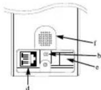
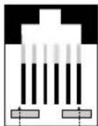
d. 6-pin modular jack
Used to connect the camera to the monitor.
e. SENSOR jack
Used to connect the sensor to the camera.
f. Speaker
It outputs the sound signal which was transferred from the monitor.
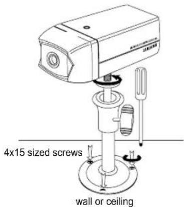
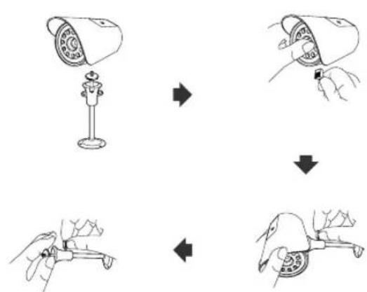
2) Installing Standard Camera(SOC-C120)
SOC-C120 camera can be attached to the wall, ceiling or shelf using the camera mount bracket (SBR-110S).
Choose an installation site that can sufficiently support the weight of the equipments to be installed.
Attach the camera mount bracket to the wall or ceiling using the supplied three screws (M4 X L15). Adjust the camera to target the video location and tighten the bracket handle on the camera mount bracket.
3) Camera Mount Bracket(SBR-110S) & Standard Camera(SOC-C120)
(1) Overview
CAMERA MOUNT BRACKET (SBR-110S) is used to attach the camera to a wall, ceiling or shelf.
(2) Specifications
Use : Indoor
Installation : Wall or Ceiling
Dimensions: 57(W) × 47.2(H) × 100.5(L) mm
2.25(W) x 1.86(H) x 3.95(L) inch
Weight : 130g (0.29 lbs)
Operating Temperature: -10^ 50^
(14^ 122^)
(3) Accessories
SCREW (M4 X L15): 3 pcs
(4) Installation
Explains the installation of CAMERA MOUNT BRACKET as wall as the installation of the camera onto the CAMERA MOUNT BRACKET.

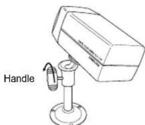
- Adjust the camera to target the video location and tighten the bracket handle on the camera mount bracket. Install the camera on to the male screw of the Camera Mount Bracket by rotating the camera in clockwise.

-
Loosen the handle by turning it in counter clockwise direction and then adjust the camera position. Tighten the handle, turning it clockwise, and lock the camera in position.
-
Connect the camera cable to the camera.
After positioning monitor and installing four cameras to a desired location, please connect CAMERA to MONITOR through CAMERA CABLE (MCB-60) as shown in the below figure. Please check whether or not it is properly connected.
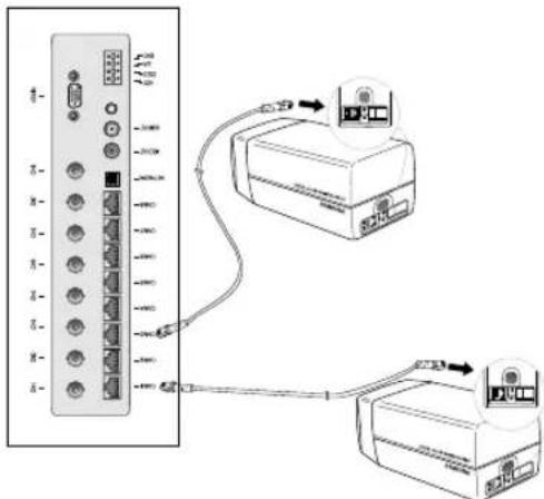
Connection status checking method :
- Turn on the monitor after connecting cameras, and check if camera image is displayed. The initial screen mode of monitor is quad mode.
In case monitor and camera is not connected, OSD 'L'(LOSS) will be displayed on screen.
2-4) Night Vision Camera
1) Before Installation
SOC-N120 INTRODUCTION
SOC-N120 Night Vision camera is intended to be used exclusively with those sold by this company for DIY. With the built-in IR LED and light sensor in the camera, both day monitoring and night monitoring are possible. Also, since it is designed as weather-proof daily product, it can be used not only indoors, but also outdoors.
2) Precautions for Installation and Operation
Installing SOC-N120
- Make sure the installation location is a place where it can tolerate 5 times of the total weight of the camera before installing.
-
When installing the camera, make sure the cable is not squeezed in an inappropriate place or the insulation plastic is removed (it will be a cause for malfunction or fire).
-
Keep personnel away from the installation location because there is a risk of object falling during installation.
* Install SOC-N120 in a cool place where there is no direct sunlight.
- Do not expose SOC-N120 to direct sunlight during operation or storage.
-
SOC-N120 should always be used in a place where certain temperature and humidity can be maintained (as specified below).
-
Temperature: -10^ 50^(14^ 122^)
-
Humidity: Below 90%
3) Installation
- Make sure the installation location is a place where it can tolerate 5 times of the total weight of the camera before installing.
- Connect the cable below the camera after attaching the provided Mount Bracket to the desired place.
- Use the handle on the Mount Bracket to adjust the direction you want to setup for monitoring.
SOC-N120
SOC-N120 Pin Configuration
| 1 SP- | |
| 2 VIDEO_OUT | |
| 3 GND | |
| 4 SP+ | |
| 5 ALM/AUDIO | |
| 6 VDD | |
4) Standard Composition

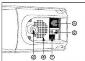
a. Lens
It has a focal length of 3.8mm and makes it possible to observe a relatively wide area.
b. Illumination Sensor
Detects incoming light to control the IR LED.
c. IR LED
This is an infrared LED that is controlled by the illumination sensor.
d. Camera fitting groove
Enables the camera to be fixed onto the bracket. You may install it either above or below the camera if necessary.
e. Speaker
Used to connect the sensor to the camera.
f. SENSOR jack
It outputs the sound signal which was transferred from alarm sensor.
g. Microphone
Capable of picking up all sound in the vicinity of the camera location and transmitting to the monitor.
h. 6-pin modular jack
Used to connect the camera to the monitor or DVR.
2-5) External terminal connecting method for Camera and Monitor
1) External terminal connecting method for CAMERA
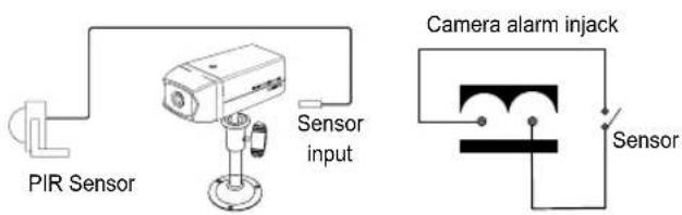
An additional PIR sensor or external sensor can also be connected.
The additional PIR sensor can be connected as shown in the above graphic.
- Sensor's trigger signal is NO (Normal Open).
- Sensor is not supplied. (Sold separately)
2) ALARM terminal connecting method.
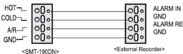
a. Connect the A/O (HOT) terminal on the rear panel to the Alarm IN terminal of the VCR.
b. Connect the A/O (COLD) terminal on the rear panel to the Ground terminal of the VCR.
c. Connect the A/R terminal on the rear panel to the Alarm Reset terminal of the VCR.
d. Connect the G (ground) terminal on the rear panel to the Ground terminal of the VCR.
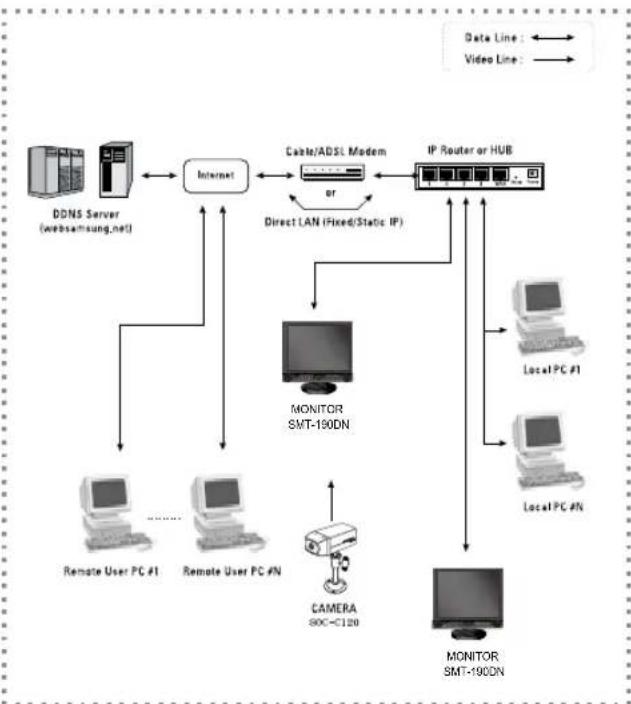
Total System Configuration
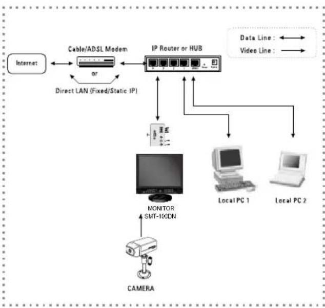
Local System Configuration
USER'S MANUAL
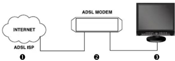
- Connect LAN cable of Cable/ADSL modem or Direct Fixed/Static IP LAN Line to WAN port of IP Router.
- Connect LAN ports of IP Router to Ethernet port SMT-190DN to be set up and to Ethernet port of Local PC to use during setup.
- Connect Video cable of Camera to MONITOR.
- Turn on the MONITOR power.

Notice
If you have a Static (Fixed) IP line or Dynamic IP line (Cable Modem or ADSL Modem) with one IP address (whether its dynamic or fixed), but have more than one internet device to use (such as a PC and a SMT-190DN or several SMT-190DN); you must use an IP Router (different from a simple Network Hub); you must set up the Router to work with the SMT-190DN; and you must use a network capable PC within the local Router network to do the setup. If you are using an existingRouter which is already set up, you may not need to redo the basic setup of the Router agian, but it is highly recommended that you at least read all the instructions below and go through the steps. Whether you are using an existingRouter or a newRouter, you must go through the Port Forwarding portion of the setup. stable power is supplied.
Chapter 3: Identifying the parts and their features
3-1) Monitor
Front
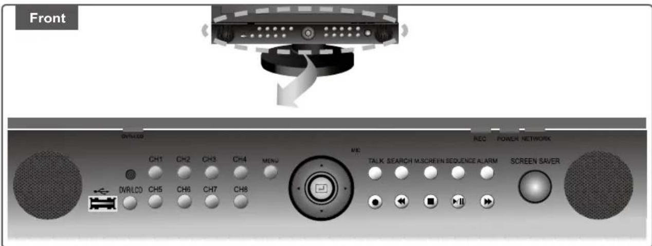
| Names Function | |
| CH1 ~ CH8 | Pressing a CH key during LIVE/PB (Live playback) will switch the screen to SINGLE MODE and the CH screen becomes FULL SCREEN DISPLAY. |
| USB PORT | A USB 2.0 that can back up the video signals currently recorded in HDD by using external memory stick. |
| DVR/LCD | Selects DVR mode or LCD mode.
If DVR mode is selected, DVR/LCD LED is red and the front key operate as DVR mode,
If LCD mode is selected, DVR/LCD LED is green and the front key operate as LCD mode. |
| MENU | Displays MAIN MENU, and pressing MENU button once more will exit the MENU screen.
Selects DVR MENU or LCD MENU according to the mode. |
| Navigation Key
(▲, ▼, □, ▼, □) | Up, Down, Left, Right, and ENTER key. |
| TALK | (1) OFF status: Audio signal input to camera microphone comes out from monitor speaker.
(2) ON status: Monitor Speaker Output OFF, audio signal input to Monitor Microphone comes out from the selected camera speaker. |
| SEARCH | Search video/audiosignals recorded in HDD by date/time they were recorded, or by selecting EVENT through RECORD, ALARM EVENT LIST. You may also view POWER EVENT LIST and LOSS EVENT LIST. |
| M.SCREEN | The screen displays 9 split screens after initial booting. LIVE/PB is also 9 split screen at the initial stage. Pressing the key will cycle between QUAD A, QUAD B, and 9 Split. |
| SEQUENCE | Pressing SEQUENCE button in Single Screen will switch and show screen of channel that currently has video input. Pressing the same button In QUAD Screen will switch and show QUAD-A/QUAD-B Screen. |
| ALARM Alarm disappeared when press alarm button |
| RECORD | Pressing REC button will illuminate LED that is at the top of REC button and start REC.
REC (●) Marker will be displayed at the top left of the screen during REC. |
| REW | Fast Reverse: Used for fast search in reverse direction during playback.
Step Reverse: Used for cut-by-cut search in reverse direction during pause. |
| STOP | Pressing STOP during PLAY/ STILL will stop PLAY and switch to LIVE screen. Pressing
STOP button in REC Mode will stop REC.
Pressing STOP button in Simultaneous Record and Playback Mode will stop PLAY, and
pressing it again will stop REC. |
| PLAY/ STILL | Pressing PLAY/ STILL button in LIVE status will switch to PLAY screen and what's recorded
in HDD is played back. Pressing PLAY/ STILL button again during PLAY will switch to STILL
status.
And pressing PLAY/ STILL button again during STILL will switch the unit back to PLAY.
PLAY/ STILL Marker will be displayed at the top of the screen. |
| FF | Fast Forward: Used for fast search in forward direction during playback.
Step Forward: Used for cut-by-cut search in forward direction during pause. |
| SCREEN Saver | (1) ON: Enters into screen save mode.
(2) OFF: Screen is displayed in a basic activation status.
(3) SCREEN SAVE Mode disables LCD control, the key and REMOTE CONTROL. |
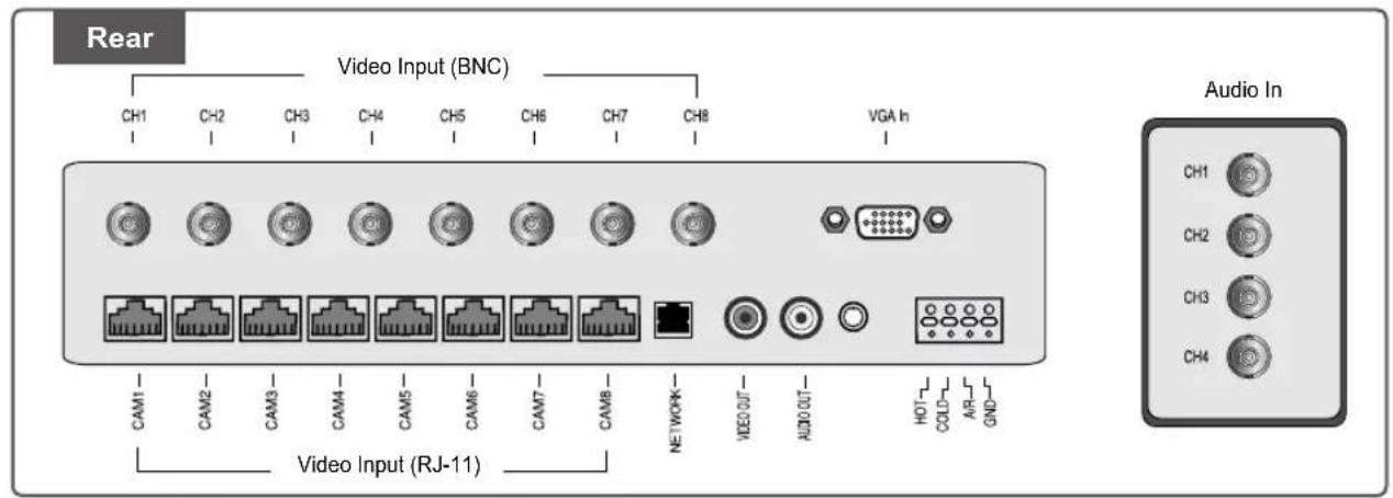
Rear
Caution
Do not connect the Video In (BNC Input) and the RJ-11 (DIY Camera) input with the same channel at the same time. Do not connect the Audio In(RCA Input) and the RJ-11(DIY Camera) input with the same channel at the same time. If connecting them simultaneously, two input signals may be mixed when outputting. This is not the product defect; so, please connect only one between the two inputs.
Symptom:
When 2 video signals are input simultaneously, the pictures overlap on the screen. At this time, noise appears next to CH when the user enters each of the menus by pressing the MENU or SEARCH key. In this case, although the noise disappears when the user exits the menu, it reappears when the user reenters the menu. Countermeasure:
Remove one of the video signal inputs causing the problem and press the M.SCREEN key. Then the noise that appeared next to CH in the MENU or SEARCH window disappears.
| Names Function | |
| Video Input(RJ11)
CH1 ~ CH8 | Connector linked to the Port DIY CAMERA(SOC-C120, SOC-N120). |
| Video Input(BNC)
CH1 ~ CH8 | Composite video signal input connector (BNC Style Connector). |
| NETWORK Connector for LAN cable connection. |
| Video Out Video signal output connector (RCA Jack) |
| Audio out Audio signal output connector (RCA Jack) |
| VGA In VGA signal input. |
| HOT Alarm output connector. Sends alarm signals to external devices. |
| COLD Connect to the ground terminal of the external devices. |
| A/R Alarm reset connector. Sends alarm reset signal to external devices. |
| GND Connect to the ground terminal of the external devices. |
| Audio In Audio Input signal connector from CH1 to CH4.(RCA Jack). |
Remote Controller

| Button Function |
| SCR. SAVE Allows users to set the monitor's SCREEN SAVE MODE. |
| 0 ~ 9 Channel | KEY/Number Key. |
| ID RESET | The Remote ID is reset to 1. |
| SYSTEM ID | SYSTEM ID setting. Press the SYSTEM ID KEY and the number keys to input the SET's ID. (Refer to SYSTEM ID. (Eng-24)) |
| M.SCREEN QUAD - A,QUAD - B, 9 split screens selection |
| VOLUME (+/-) Increase and Decrease sound volume from the monitor. |
| PIP Picture In Picture. |
| ZOOM X2 screen in Single Channel. |
| FREEZE | Allows users to see a target camera picture in the PAUSE MODE. |
| MENU | Displays menu items. Use this also to exit the sub menu and return to the menu at the next highest level. |
| DVR/LCD Selects DVR mode or LCD MONITOR mode. |
| LIVE/P.B /TRIPLEX | LIVE/PB/TRIPLEX modes are converted in sequence |
| SEARCH Search video/audiosignals recorded in HDD. |
| ▼,▲,◇,◆ | ▼,▲,◇,◆ directional keys.
◆key is used for Fast Forward during playback and Step Forward during pause.
◆key is used for Fast Reverse during playback and Step Reverse during pause. |
| ENTER use to select a menu item or to accept the changed value. |
| ▶■ | Plays back DVR recorded data. Temporarily stops during playback. |
| ■ | Stops DVR playback or recording. |
| ● | Records live video. |
| ✕ | Lock STOP keys during recording to prevent accidental operation of the unit. |
| VGA PIP | PIP - Available in VGA Mode
Push the PIP button to turn PIP screen On/Off. |
| MUTE | Press to mute the sound temporarily. Displayed on the bottom left of the screen. Press the MUTE button again to cancel the Mute function. Alternatively press the - or + button to cancel the Mute function. |
| AUTO | Available In VGA mode Only
Adjusts the screen display automatically. |
| SOURCE | Press the 'SOURCE' button to change the input signal source. Changing the source is allowed only in external devices that are connected to the monitor at the time. [DVR / VGA] |
| UNDER SCAN Displays the entire video signal on the screen. |
| P.MODE | Available in DVR Mode Only.
Press to select a pre-defined Picture Mode of the monitor or to change the picture atmosphere as required. When you press this button, current mode is displayed on the lower center of the screen. The monitor has four automatic picture settings that are preset at the factory. Then push button again to circle through available reconfigured modes. (Dynamic, Standard, Movie, Custom) |
Chapter 4: Basic Use
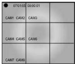
4-1) Power On

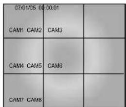
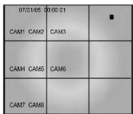
LED turns on and the system boots displaying the following screen when power switch.
"SYSTEM STANDBY..." is displayed.

| 07H01/05 0000 | 001 | |
| CAM1 CAM2 | CAM3 | |
| CAM4 CAM5 | CAM6 | |
| CAM7 CAM8 | | |
If there is no video signal when turning the system on, the black screen appears with an "L" indicator, which is an abbreviation of "LOSS" at the side of title(CAM1...CAM2) as follows. "L" disappears as soon as the video signal is connected. "Video loss event" is indicated in the "Loss event menu" in search mode.
| 07/01/05
CAM1 CAM2 CAM3 | 00:00:01
CAM1 CAM2 CAM3 | |
| CAM4 CAM5 | CAM6 | |
| CAM7 CAM8 | | |
4-3) Basic screen
1) Full screen
All of marks and conditions displayed in the screen are as follows.
| TU Q7
AML CAM1 S | 105 00:00:01
CAM2 CAM3 | |
| CAM4 CAM5 | CAM6 | |
| CAM7 CAM8 | | |
| 05/01/05
00:00:01 | When in "LIVE" mode, it shows the present date and time set in the system.
When in "PLAYBACK" mode, it means the recorded date and time of data. |
| Record function |
| A | Is displayed when the system is in the alarm recording mode. |
| ↑ | Prevents the cancellation of REC. |
| L Indicates "VIDEO LOSS". |
| M | Is displayed when the system is in the motion recording mode. |
| S | Indicates "Sound Select" |
| ▲ PLAY | Indicates normal speed playback. |
| ← 2 | Indicates X 2 reverse playback. |
| ← 4 | Indicates X 4 reverse playback. |
| ← 8 | Indicates X 8 reverse playback. |
| ← 16 | Indicates X 16 reverse playback. |
| ← 32 | Indicates X 32 reverse playback. |
| ← 64 | Indicates X 64 reverse playback. |
| → 2 | Indicates X2 forward playback. |
| → 4 | Indicates X4 forward playback. |
| → 8 | Indicates X8 forward playback. |
| → 16 | Indicates X16 forward playback. |
| → 32 | Indicates X32 forward playback. |
| → 64 | Indicates X64 forward playback. |
| U | Displays USB connection status. |
| T | Displays when the timer record is set. |
This monitor was set to password lock when you purchase a new set. Therefore, you must first enter 4digit password to activate the OSD. The default password for a new set is "4321".
Pressing the FRONT PANEL MENU button allows users to enter the SETUP MENU and see the following OSD menu box. Setting method of each SETUP MENU function and operation is as follows.
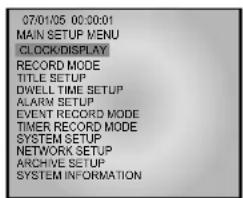
- CLOCK/DISPLAY
- Date, Time, and Display item setup
- RECORD MODE
- Recording-related item setup
- TITLE SETUP
- Channel title setup
- DWELL TIME SETUP
- Screen Time by channel during SEQUENCE activation setup
- ALARM SETUP
- Alarm channel setup and alarm-related item setup
- EVNET RECORD MODE
- Recording item and motion detection item during alarm setup
- TIMER RECORD MODE
- Reserved recording schedule setup
- SYSTEM SETUP
- System initialization and password setup
- NETWORK SETUP
- Network-related item setup
10.ARCHIVE SETUP
- Data Archive menu setup
- SYSTEM INFORMATION
- HDD capacity and System S/W Version display
5-1) CLOCK/DISPLAY SETUP
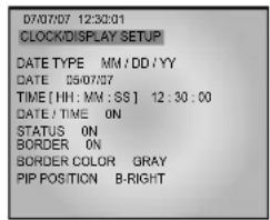
1. DATE TYPE
- Three date display types are available and User may select a desired type.
[YY/MM/DD,MM/DD/YY,DD/MM/YY]
- Change date type using , , , key.
Then click key.
2. DATE
- You may set up current date.
- Change date (year/month/date) using , , , key. Then click key.
3. TIME
- You may set up current time.
- Change time (hour, minute, second) using , , , key. Then click key.
4. DATE/TIME
- To display date and time to the default screen, you may select ON from ON/OFF to display them, or OFF if you don't want them to be displayed. [ON/OFF]
- You may set ON/OFF using , , , key. Then change it using key.
5. STATUS
-
When recording, locking the system, and playing recorded video, you may set ON/OFF to ON to show system status such as playback information. Set to OFF if you don't want the information to be displayed. [ON/OFF]
-
You may select ON/OFF using , , , key. Then change it using key.
6. BORDER
- Show or hide screen border. Select ON or OFF to show or not to show screen border. [ON/OFF]
7. BORDER COLOR
- Split screen's border can be set in three colors. [GRAY/WHITE/BLACK]
- Select ON/OFF or Color (GRAY, WHITE, BLACK) using , , , key. Use key to change selection.
8. PIP POSITION
[B-RIGHT/B-LEFT/T-RIGHT/T-LEFT]
- Select PIP (B-LEFT, B-RIGHT, T-LEFT, T-RIGHT) location using , , , key.
Use key to change selection.
- Quality of the video to be recorded is defined in three stages. HIGH means quality of the video to be recorded is the highest, then NORMAL, then LOW. [NORMAL/HIGH/LOW]
- Select video quality using , , , key. Use key to change it.
2. FIELD RATE
- Set numbers of fields to be recorded.
-8CH Mode [NTSC][1/2.5/3.75/7.5 IPS] [PAL][0.8/1.6/3.1/6.3 IPS]
- 1CH Mode [NTSC][1/2.5/3.75/7.5/15/30 IPS] [PAL][0.8/1.6/3.1/6.3/12.5/25 IPS]
3. DISK END MODE
- Setting to STOP will stop recording when HDD becomes full during recording.
- Setting to CONTINUE will overwrite previously recorded data with the one currently being recorded. The oldest data saved in HDD will get overwritten first. [CONTINUE/STOP]
- Use , , , key to change the setup.
4. DISK END ALARM TONE (Notice Mode when HDD is full)
- When DISK END MODE is set to STOP, setting this to ON will make ALARM TONE ring when HDD is full during recording. If it is set to OFF, ALARM TONE will not ring. This feature won't be activated unless DISK END MODE is set to STOP. [ON/OFF]
-Use , , , key to change the setup.
5. RECORD TIME MARK
- Setting to ON will show the time when the recording is done during playback, Setting to OFF will not show it. [ON/OFF]
-Use , , , key to change ON or OFF.
6. RECORD TITLE MARK
- Setting to ON will show the title when the recording is done during playback, Setting to OFF will not show it. [ON/OFF]
- Use , , , , key to make change.
5-3) TITLE SETUP
- Function: Set the desired title of each camera.
- Setting method: Move to TITLE SETUP MENU by using / KEY in the SETUP MENU, and press the ENTER key SWITCH to display the OSD as shown in the figure below. (The figure shows the initial setting status.)
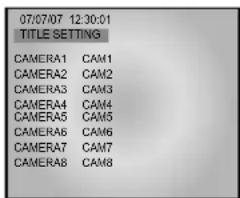
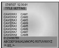
Move to a target camera channel by using / KEY, then press the ENTER KEY to display a cursor at the space of the first character in the camera title. Move the cursor to a target character in the OSD box lower part by using / KEY, then press the ENTER KEY to set the character.
The cursor automatically moves to the next space after one character is set. Set the title of camera by repeating the same method.
(Only eight characters are available for a camera title.)
5-4) DWELL TIME SETUP
The initial setup status of DWELL TIME SETUP menu is shown below.
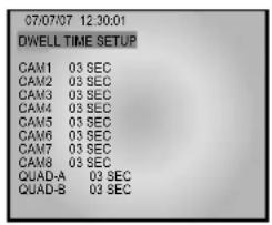
1. DWELL TIME SETUP
- Pressing SEQUENCE button in Single Screen will bring up the SEQUENCE MODE. You may set the time display for each channel. If you set zero (0) seconds as the DWELL TIME for a particular channel, the set channel will be skipped and next channel will be shown. You may set time in the QUAD-A, QUAD-B screens.
[0SEC, 1SEC, 2SEC, 3SEC. ~60SEC]
-Use , , , , key to make changes.
5-5) ALARM SETUP
- Function: Allow users to set the ALARM MODE for each camera.
- Setting method: Move to ALARM SETUP MENU by using / KEY in the SETUP MENU, and press the ENTER SWITCH to display the OSD as shown in the figure below. (The figure shows the initial setting status.)
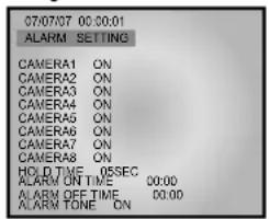
(1) CAM1 to CAM8 item sets whether the alarm sensor connected to the camera is used or not. (ON: Alarm function setting, OFF: Alarm function canceling)
(2) HOLD TIME item sets time to freeze alarm operation when alarm occurs.
(HOLD TIME to be set: 05SEC ~ 1MIN ~ 30MIN)
Note
If you want to carry out the alarm operation, you must preset ALARM ON/OFF TIME in monitor before CAMERA ALARM is set to ON.
(3) ALARM TONE sets whether or not alarm tone (high-pitched tone)sounds when an ALARM occurs. (ON: ALARM TONE operation, OFF: Cancel)
The initial setup status of EVEVT RECORD SETUP menu is shown below.
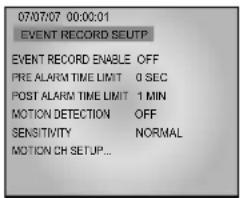
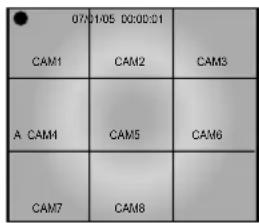
1. EVENT RECORD ENABLE
If you want to start recording when Alarm goes off, then select ON. If you do not want to start recording when Alarm goes off, then select OFF. If you set EVENT RECORD ENABLE to ON and exit the menu, system starts recording whenever Alarm is activated. The following screen shows that ALARM recording is in progress when ALARM is activated. It shows the ALARM for Channel 4 is activated with a "A" mark. [ON/OFF]
2. PRE ALARM TIME LIMIT
-
PRE ALARM recording is a feature that recognizes what kind of conditions were present immediately before motion was detected. PRE ALARM TIME LIMIT can be set to record 5 seconds of video right before motion detection or an ALARM occurrence. The System memory always saves up to 5 seconds of video data. When motion is detected or an ALARM occurs, ALARM recording starts and PRE-ALARM data is simultaneously recorded from the System memory to HDD up to the time length set in PRE ALARM TIME LIMIT. [0SEC, 5SEC]
-
Use , , , , key to make changes.
3. POST ALARM TIME LIMIT
- Recording is performed up to the time set in MAIN ALARM TIME. Then data is further recorded up to the time set in POST ALARM TIME LIMIT. [10SEC,20SEC,30SEC,1MIN,2MIN,3MIN,4MIN,5MIN]
-Use , , , key to make changes.
4. MOTION DETECTION
-
When MOTION DETECTION is set to ON, recording will start whenever a motion in the input video is detected. [ON/OFF]
-
Use , , , , key to make changes.
5. SENSITIVITY
-
MOTION DETECTION SENSITIVITY can be set when user set the MOTION DETECTION. There are three stages -- HIGH/NORMAL/LOW. [HIGH/NORMAL/LOW]
-
Use , , , , key to make changes.
6. MOTION CH SETUP
- Set the channel that you want to detect MOTION.
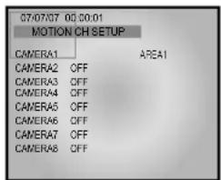
You can divide the motion detection area into total 9 for each channel. The following screen displays to activate only No. 1 area of No. 1 channel.
You can use the direction key to move the area around and select FULL for the motion detection on the whole screen. With MOTION DETECTION set to ON, if motion is sensed in other areas where MOTION DETECTION is not set to ON, MOTION DETECTION will not operate.
- Motion is detected only from channels set to 'On'. The following screen shows motion recording after motion detection. A motion is detected in the Channel 4. The 'M' mark before the title of each channel indicates that a motion is detected. [OFF/AREA1/AREA2/AREA3/AREA4/AREA5/ AREA6/AREA7/AREA8/FULL]
| 07/01/05
CAM1 | 00:00:01
CAM2 | CAM3 |
| M CAM4 | CAM5 | CAM6 |
| CAM7 | CAM8 | |
5-7) TIMER RECORD MODE
- TIMER: Set this option to ON to setup Timer Recording [ON/OFF].
DAY: Select the day of a week for the timer recording [MON, TUE, WED, THU, FRI, SAT, DAILY, SUN].
- START & END: Set the starting and ending time for the timer recording [00:00 ~ 23:59].
- FIELD RATE: Set the number of fields to be recorded per second [NTSC][1/2.5/3.75/7.5 IPS] [PAL][0.8/1.6/3.1/6.3 IPS].
- Use , , , key to make change.
Caution
There are three types of recording modes: Event Recording (Motion Detection & Alarm), Timer Recording, and Normal Recording. If all three recording modes are selected at the same time, recording takes place in the order of Event, Timer, and Normal.
5-8) SYSTEM SETUP
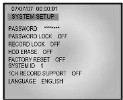
1. PASSWORD
The default password: 4321
- You can set the password to limit unauthorized access to the Main Screen setup menu. (Create a eight-digit password by choosing between 1~8.)
You can enter the password using the corresponding channel key.
2. PASSWORD LOCK
- If PASSWORD LOCK is set after you assigned a PASSWORD, you must enter PASSWORD each time you enter to MENU. [ON/OFF]
-Use , , , , key to make changes.
- Use a 1 to 8 digits alphanumeric key to enter PASSWORD and press the OK key using the / key.
- If your PASSWORD is mismatched 3 times or more, the display is moved to MULTI screen.
- "password FAIL" is displayed when your password is mismatched or when you enter 4 digit more password.
3. RECORD LOCK
If you set RECORD LOCK to ON and press STOP to release the current recording, you are prompted to enter the PASSWORD. [ON/OFF]
4. HDD ERASE
If you set HDD ERASE to ON, you will see a message of "SYSTEM HDD ERASE?" that asks if you want to erase the data on the HDD. If you click OK, you'll see "HDD ERASE" as in the next picture, and the existing HDD Data is erased. If you click CANCEL, the HDD data will not be erased.
If you erase HDD, system will reboot and format HDD automatically. It takes about 2 minutes to format. [ON/OFF]
Caution
Deleted data cannot be restored. Check data carefully again before deleting.
5. FACTORY RESET
When FACTORY RESET is performed, the setup value will factory default setting when initialization starts.
- Select SYSTEM SETUP from MENU screen.
2.From the SYSTEM SETUP submenu, set FACTORY RESET to ON.
3.When you exit MENU, the phrase "FACTORY RESET" appears on the monitor and the initialization starts. [ON/OFF]
- Use , , , , key to make changes.
6. SYSTEM ID
Set the System ID to use the Remote Controller.
When using more than one unit of the system, a number of systems may be operated at the same time with a single remote controller. Set the different IDs for different units. Press the System ID of the Remote Controller and use the number keys to create IDs.
After the setting, systems with IDs that correspond to the ID of the remote controller will operate. [0,1,2 8,9]
Note
You must set the same SYSTEM ID of the DVR menu and LCD menu to use system ID function. and set the same SYSTEM ID for the remote controller too. If the SYSTEM ID of the DVR menu is differ from the LCD menu's, the remote controller may not operate properly. Set the SYSTEM ID of the LCD menu at LCD menu > Setup Menu > System ID. Press the number button that you want on the remote controller while SYSTEM ID button is pressed for setting the SYSTEM ID of the remote controller.
7.1CH RECORD SUPPORT
If you set 1CH RECORD SUPPORT to ON, the system switches from 8-channel to 1-channel mode. Then, the number 1 channel will be selected.
If you set 1 CH RECORD SUPPORT to ON, you will see a message of "SYSTEM CHANGE 1CH DVR?" that asks if you want to change the SYSTEM into 1 channel mode. If you click OK, the system switches. Once the system switched to 1 channel mode, all system functions operate in 1 Channel mode and the items of other channels in the MENU are deactivated.
Once the system switched to 1 channel mode, you can just play the data in this mode and the data recorded in 8 Channel mode could not be played.
On the contrary, in 8 Channel mode, the data recorded in Channel 1 mode will not playback and only the data recorded in 8 Channel can be played. If you want to switch from 1 channel mode back to 8 channel mode, set 1CH RECORD SUPPORT to OFF and exit the MENU. Then, you will see a message, "SYSTEM CHANGE 8CH DVR?" asking if you want to switch the system mode. If you click OK, the system will be switched. [ON/OFF]
8. LANGUAGE
Many language are provided and select a your language. English is the default.
[ENGLISH/FRANÇAIS/DEUTSCH/ESPÁÑOL/ITALIANO/PYCCKM/N/SVENSKA/PORTUGUES/POLOK/K/CESKY/ TÜRKÖE/DUTCH/DANSK/HRVATSKI]
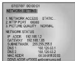
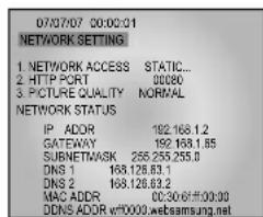
5-9) NETWORK SETUP
This section of the manual is intended for users who will install this security system in a network environment. If you have difficulty setting the network, we recommend contacting your network administrator.
Static
DHCP
- PPPoE(ex.ADSL)
- Function: Allow users to select the STATIC (fixed) IP, DHCP, PPPoE of Setting.
- Setting method: Move to, NETWORK SETUP MENU by using / KEY in the SETUP MENU, then press the ENTER SWITCH to display the OSD as shown in the figure below. (The figure shows the initial setting status)
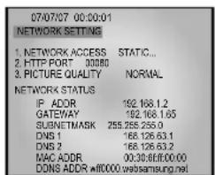
MOVE TO EACH item by using / KEY, and using KEY to change the set value.
Static IP User
- Constituted by Static IP on the TCP/IP network
1) Move to 'STATIC...' by using / KEY at NETWORK ACCESS, then press ENTER SWITCH to set
STATIC...
(STATIC: Select in case the network configuration of monitor is fixed IP (Public or Private IP)
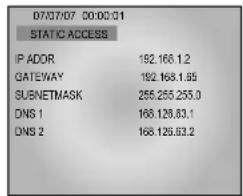
2) Move to IP ADDR / GATEWAY / SUBNETMASK by using / KEY.
3) Press ENTER SWITCH and type in IP ADD GATEWAY / SUBNETMASK respectively.
4) DNS 1 and DNS 2 will be automatically set to DNS as shown above. Use / KEY to change it.
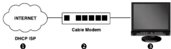
DHCP User
- Constituted by Dynamic IP on the cable/xDSL modem network
You can use the SMT-190DN products through the network using Dynamic IP on cable/xDSL modem. In this case, it should be connected with DDNS to support the Dynamic IP. In case of a configuration using DHCP, as the connection to SMT-190DN is made using domain names (EX: http://wff0000.websamsung.net) that are automatically registered in our DDNS server, IP address, Subnet Mask and Gateway that are in the network tab of Admin Mode are not to be changed. The proper domain names of SMT-190DN are automatically registered to DDNS server installed in our company in case of modem connection. The default IP type is DHCP.
1) Connect as the figure below and turn on the power of the equipment in the order shown.
2) After setting, move to the main screen by using the MENU button.
3) Set values will be stored shown below. It takes 30 to 35 seconds.

4) Open your Internet Explorer web browser.
Using a Static (fixed) IP, You may also connect remotely by typing in the IP address of the SMT-190DN, Such as
http://192.168.1.200

HTTP Port
Set the port to be used when connecting to SMT-190DN in Internet Explorer and receive necessary files for image transmission.
The port setting is used for various network configurations or a particular port etc.

Caution
A port number is reserved for TCP port and HTTP port setting. Default values should not be changed. However, if the IP Router is used in a network environment, input proper values with reference to the IP Router manual.
If the SMT-190DN is using a Router, you may also connect remotely by typing in the WAN IP Address of the Router and the HTTP port assigned to the SMT-190DN. (here you must type in the port address even if it is the default "80"), such as
http://192.168.1.200:80
1) Move to 'DHCP...' by using / KEY in NETWORK ACCESS, then press ENTERSWITCH to set to DHCP.
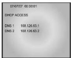
2) DNS 1 and DNS 2 will be automatically set to DNS as shown above. Use KEY to change it.
3) After setting, move to the main screen by using the MENU button.
4) Set values will be stored as shown below. It takes 30 to 35 seconds.

5) You can view the video source of the SMT-190DN from a remote location PC.
6) Open your Internet Explorer web browser, type in the following in the URL window and press Enter.
http://wff0000.websamsung.net
- Where ff0000 is the MAC address of your SMT-190DN in this example. If your SMT-190DN MAC address is ff0001, then type in ff0001 instead of ff0000.

MAC Address.
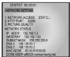
Locate the MAC Address of the SMT-190DN (each SMT-190DN has its own unique MAC address) It can be checked in "5-9) NETWORK SETUP" of SETUP MENU'. It is the last 6 digits as shown below.

If you change the HTTP port number 80 to 1025, then you must type in as the address bar below. The default port number is 80. You may need to change the port number if you cannot link to the security system from a remote location due to a firewall or if you have other issues.
http://wff0000.websamsung.net:1025
- At this time, you should add "w" in front of "mac address".
DSL User (PPPoE)
- Constituted by IP on PPPoE (DSL)
SMT-190DN products can be used on the network using IP through PPPoE (DSL). In case of a configuration using PPPoE, SMT-190DN connection is made through the domain names (EX: http://wff0000.websamsung.net) that are automatically registered in Samsung's DDNS server. You do not need to enter IP address, Subnet Mask and Gateway in the network tab of Admin Mode.
1) Connect as in the figure below and turn on the power of each piece of equipment in the following order.
2) MOVE TO EACH item by using / key, and / KEYchange the set value.
3) Move to PPPoE...' by using NETWORK ACCESS. Press ENTER SWITCH to set to PPPoE.
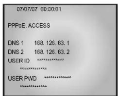
4) When accessing the PPPoE (DSL), type in the User Name and Password (and Confirm Password) given to you by the DSL Service Provider.
Caution
When using DSL (ISP-internet service provider) you must type correct User Name and Password to connect to SMT-190DN. If you type an incorrect User Name or Password, communication is impossible.
* ID and PASSWORD
5) USER ID and PWD (Password)are limited to 40 digits maximum. Only numerals, @symbol and small characters can be used. Capital letters are not supported.
6) DNS 1 and DNS 2 will be automatically set to DNS as shown above.
7) Use KEY to change it.
8) After setting, move to the main screen by using the MENU button.
9) Set values will be stored as shown below. It takes 30 to 35 seconds.

10) You can view the video source of the SMT-190DN from a remote PC.
11) Open your Internet Explorer web browser, type in the following in the URL window and press ENTER.
http://wff0000.websamsung.net
For example, if your SMT-190DN MAC address is ff0001, then type in ff0001 instead of ff0000. W is a fixed letter that must be typed in. This will ensure connection to the monitor.
Note
MAC Address.
Locate the MAC Address of the SMT-190DN (each SMT-190DN has its own unique MAC address)
It can be checked in "5-9" NETWORK SETUP" of SETUP MENU'.
It is the last 6 digits as shown below.
- At this time, you should add "w" in front of "mac address".
Caution
If you change the HTTP port number 80 to 1025, then you must type in as the address bar below. http://wff0000.websamsung.net:1025
Caution
In cases where the PC's DNS server address is not set and the connection using domain name is not available, Please consult your network administrator to set DNS server address.
Caution
The connection to SMT-190DN is unavailable for about 2~5 minutes after powering on your DSL Modem. Since the connection is not available, as the IP is not received from DSL communications, please reboot by turning off the power of DSL Modem and SMT-190DN for more than 5 seconds, and then try to connect again.
5-10) ARCHIVE SETUP
The initial setup status of ARCHIVE SETUP menu is shown below.
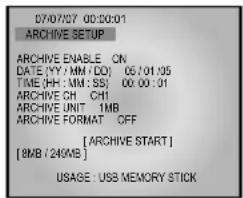
1.ARCHIVE ENABLE
- If you would like to move HDD DATA to USB memory stick, set the ARCHIVE ENABLE to ON.
- This is the USB MODE and you can't record a picture to HDD. You must set the ARCHIVE ENABLE to OFF for recording a picture to HDD. [ON/OFF]
2. DATE (YY/MM/DD)
- Set the date that you want to save data to USB.
-Use , , , , key to make changes.
3. TIME (HH:MM:SS)
- Select a time you would like to back up your data from.
- Use , , , , , key to make changes.
4.ARCHIVE CH
- Set the channel that you want to save data to USB. [CH1, CH2, CH3, CH4, CH5, CH6, CH7, CH8]
- Use , , , , key to make changes.
5. ARCHIVE UNIT
- Set the data capacity unit that you want to save data to USB.
If you select 1MB, data will be stored up to 1MB
from the selected date and time of the selected channel. [1MB, 2MB, 3MB]
-Use , , , to make changes.
6. [ARCHIVE START]
- If press ENTER KEY after moving cursor to " [ARCHIVE START]", DATA ARCHIVE begins.
7. [8MB/249MB]
- If user uses 256 MB USB MEMORY STICK and stores 8 MB of DATA to USB MEMORY STICK, "[8MB/249MB]" is displayed.
"8MB" is used capacity and "249MB" is total USB capacity.
External USB
- The compatible USBs are as follows.
| Mark Model Name | Capacity | |
| AL Tech | AnyDrive | 256MB, 512MB |
| SanDisk | Cruzer Mini | 256MB, 512MB |
| GeekSquad | GeekSquad | 256MB, 512MB |
Caution
The only supported USB DEVICE is a USB MEMORY STICK.
This initial setup status of SYSTEM INFORMATION menu is shown below.
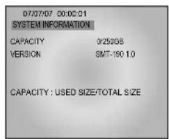
1. CAPACITY
- Shows HDD capacity of the system. USED SIZE/ Total HDD capacity
2. VERSION
Chapter 6: Recording
6-1)REC(Normal)
Press the () button to record the live screen. The LED on the record button turns on, the mark is displayed in the screen to indicate the HDD recording. All eight sources will be recorded simultaneously.
Note
If the user is in the menu, the recording does not start by pressing the ( button.
To start the recording, press the ( button after the user exits from the menu.
Caution
If the input video signal is disconnected during the recording, the recording is stopped. The system resumes the recording as soon as the input video signal is connected normally. The system does not start the recording when no video signal is received.
6-2) Record Stop
Click the stop button to stop the data being recorded. -REC mark disappears and the recording is stopped.
Note
Press the Menu button after you stop the recording first and the menu screen will be displayed.
To search the data recorded, press the ( ) button in the LIVE mode. The following menu is displayed.
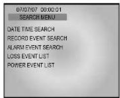
- DATE/TIME SEARCH : Searches data recorded by Date or Time.
- RECORD EVENT SEARCH: Searches all of data recorded in normal recording mode.
- ALARM EVENT SEARCH : Searches data recorded by occurrence of Alarm or Motion.
- LOSS EVENT LIST : Displays the channel and time information when the video loss occurs.
- POWER EVENT LIST : Displays the time information when the power goes on/off.
Caution
The current date and time are shown in the Date/ Time Search Menu. The List is not displayed in the Event Search Menu because there is no data in the HDD at the time of shipment.
7-2) DATE TIME SEARCH
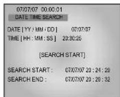
1. DATE[YY/MM/DD]
- Set a date to search[YY,MM,DD].
- Use the , , , , key to change the date.
2. TIME[HH:MM:SS]
- Set a time to search.
- Use the , , , , key to change the time.
3. SEARCH START
- Input [YY/MM/DD] and [HH:MM:SS] to search and press the ENTER ( ) button. And then, the related data is searched.
- Use the , , , , key to change.
After pressing the search button, select the record event search menu. The following screen is displayed.
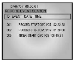
If you press the REC button among the data recorded in the HDD, the data list recorded is displayed. Select the record event list with the , key. Press the ENTER button to search it.
7-4) ALARM EVENT SEARCH
After pressing the search button, select the ALARM EVENT SEARCH. The following is displayed.
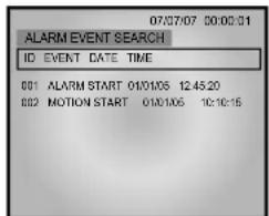
- The data recorded on the HDD due to alarm occurrence or motion is displayed by the recording time. Select the ALARM/MOTION EVENT LIST by use of the , key. And press the button to search it.
The information including the channel, date and time is displayed when VIDEO LOSS occurs.
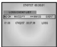
It is possible to check the list of next page by use of key.
Displays the date and time information with the list when the power is turned on.
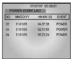
It is possible to check the list of next page by use of - key.
7-7) BASIC PLAYBACK
Press the PLAY/STILL button to play the data recorded in the HDD immediately.
Playback starts displaying the following screen.
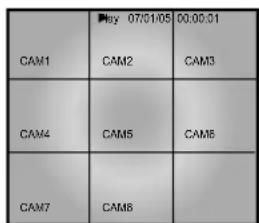
If there is no data recorded, "NO DATA" message is displayed.


Note
- If the user is in the menu, the playback does not start even if the PLAY button is pressed. Exit from the menu first to start the playback.
- Press the stop button to stop the playback. If the PLAY/STILL button is pressed again, the system starts the playback from the last stop.
- If the final data of HDD finishes playing back, the first data of HDD is played again.
If the PLAY/STILL button is pressed during the playback, the following screen is displayed and the screen is paused.
| Play 07/0145 | 05:00:01 | |
| CAM1 CAM2 | CAM3 | |
| CAM4 CAM5 | CAM6 | |
| CAM7 CAM8 | | |
| 07/5105 D321 | |
| CAM1 CAM2 | CAM3 | |
| CAM4 CAM5 | CAM6 | |
| CAM7 CAM8 | | |
- If the REW or FF button is pressed during the PLAYBACK mode, X2 playback is performed in forward or reverse.
- If the REW or FF button is pressed repeatedly during the STILL mode, still playback is performed backwards or forwards.
- Press the FF button to increase the forward playback speed, and press the REW button to increase the reverse speed during X2 playback
| 2 07/01/05
CAM1 CAM2 | #00:01
CAM3 | |
| CAM4 CAM5 | CAM6 | |
| CAM7 CAM8 | | |
| 2070105 CAM1 CAM2 | #0001 CAM3 | |
| CAM4 CAM5 | CAM8 | |
| CAM7 CAM8 | | |

Note
The menu screen is not displayed even if the user presses the menu button during playback. Change to the LIVE mode to display the menu screen.
Chapter 8 : Remote Viewer Connection
8-1) SMT-190DN basic settings
1) Open your Internet Explorer web browser. Type in the Monitor's IP address or MAC address in the URL and press ENTER. (for example: http://168.219.13.232, http://wff0000.websamsung.net)

Note
Where ff0000 is the MAC address of your SMT-190DN in this example. If your SMT-190DN MAC address is ff0001, then type in ff0001 instead of ff0000.
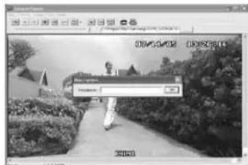
2) When you choose the Admin. menu, it asks you for the Admin ID and password.
3) Type in root/root. The default Admin. ID is "root" and Admin. password is "root".
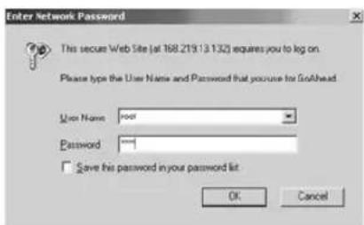
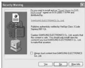
4) Click YES. This will automatically download the necessary Active X Controls to operate the Remote Viewer. It takes about 20 seconds at the first connection.
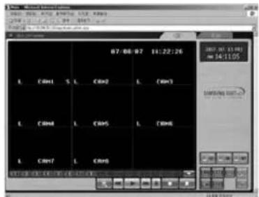
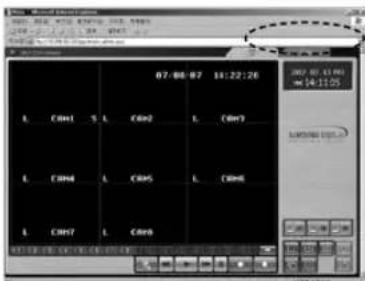
5) When you enter properly, a window appears as shown below.
Note
If the MPEG 4 codec is improperly installed, you will not see video images. To see video, click on "8Ch DVR Viewer" in the upper left portion of the screen, then a window will appear prompting you to install MPEG 4.
- CAMERA SELECT
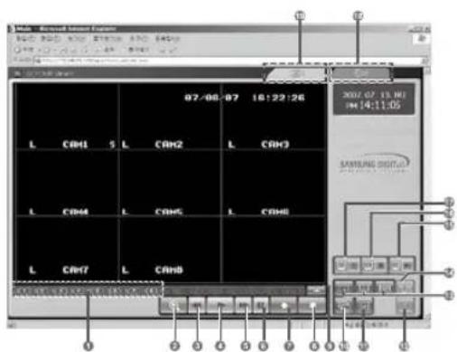
| KEY Type Function |
| 1 | Choose a camera by selecting channel "Ch 1 ~ Ch 8" 8 Cameras are supplied. |
| 2 | DVR SEARCH |
| 3 | DVR REWIND |
| 4 | DVR PLAY |
| 5 | DVR FAST FORWARD |
| 6 | DVR STILL |
| 7 | DVR RECORD |
| 8 | DVR STOP |
| 9 | NEXT CHANNEL |
| 10 | SEQUENCE MODE |
| KEY Type Function |
| Φ | | IMAGE RESIZE (ch1 Default selected)
320 X 240 Size
720 X 480 Size |
| Φ | | SAVE PATH |
| Φ | | 1 CHANNEL SELECT
4 CHANNEL SELECT
9 CHANNEL SELECT |
| Φ | | CAPTURE |
| Φ | | PC PLAY |
| Φ | | PC STOP |
| Φ | | PC RECORD |
| Φ | | ADMIN MODE |
| Φ | | LIVE MODE |
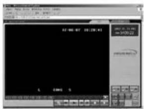
- SINGLE SCREEN DISPLAY
If users want to see the camera image at full mode or smaller, select a target camera with NEXT channel or CHANNEL SELECT keys.
After camera selection, camera image can be displayed at full screen.


DISPLAY
Original Size
Large Size
- QUAD MODE DISPLAY
- Users can select the QUAD mode
QUAD-A->QUAD-B->QUAD-A->...

QUAD MODE DISPLAY
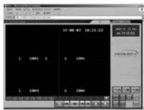
QUAD - A : QUAD DISPLAY MODE From Camera1 to Camera4
QUAD-B:QUAD DISPLAY MODE From Camera5 to Camera8
- Auto SEQUENCE DISPLAY MODE
Press the sequence key in the single or QUAD mode to display the screen in sequence.
If the DWELL TIME SETTING of SETUP MENU is set to 3 seconds and the SEQUENCE KEY is pressed at this time, the operation will be carried out as follows.
(Channels with no signal will be skipped while single screen is auto-switching)
\* SINGLE MODE SEQUENCE DISPLAY

Press SEQUENCE KEY When SINGLE MODE (camera select key) is displayed at full screen.
* QUAD MODE SEQUENCE DISPLAY

Press SEQUENCE KEY When QUAD - A (QUAD - B) MODE is displayed.
-SAVE MODE

Press the SAVE PATH KEY to change the name of the DI-RECTORY.
- CAPTURE MODE

Press the CAPTURE KEY to store each picture in the form of FMPI (still image file).
- Motion Picture Recording and Playback

1. Recording
When saving with Viewer, the file and folder are created automatically. If the Mac address of product is "00-30-6F-FF-00", the created file and folder are as follows.
C:Documents and Settings\Owner\AppData\LocalLow\Samsung\SDVRWEB00-30-6F-FF-00-00"
A user can change the name of a file or folder by using the save path key ( ) of the Viewer.
If you are connected to and recording from more than one SMT-190DN on the same PC, there will be more than one "Server Name" directory. You can always locate the file by choosing the Server Name directory. Within the Server Name directory, files are automatically saved with file names in time stamped format.
- The maximum time of the recording in Remote Viewer is 10 minutes.
2. PLAY

When you select play and double click the file, that file will play back on the Remote Viewer as a motion clip.
3. PLAYER
- Player installation/execution/deletion
- Installation
Player will be installed together when it is connected to SMT-190DN.
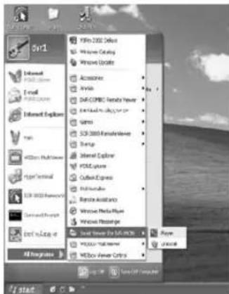
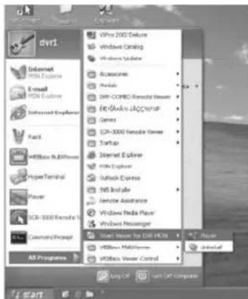
- Execution (Follow the instruction to execute it separately.)
Click Start Program Smart Webviewer For DVR-MON(190) Player.
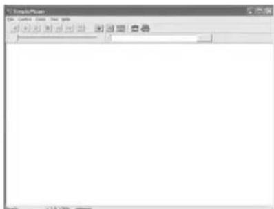
- Program screen configuration
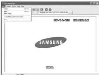
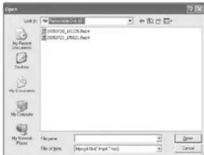
File - Open... Selecting this, you can choose between cmp4(moving image file) or in the window as shown below.
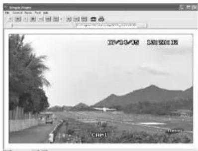
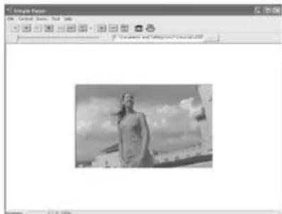
Having chosen and opened a file, you will see a picture such as shown below.
-
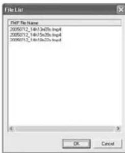
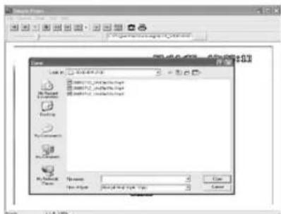
How to Play Back ARCHIVE FILE (*.fmp4)
-
Connect the device to the Computer's USB connector. You will see the files(fmpi, fmp4)which are saved in the removable storage.
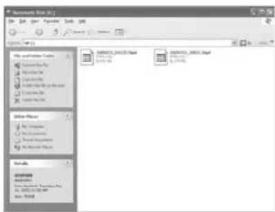
- Click and run the "Player" from the "Smart Viewer for DVR_MON" program group under the Start All Programs
- The Simple Player window appears as shown below.
- Click the File Open button from the menu.
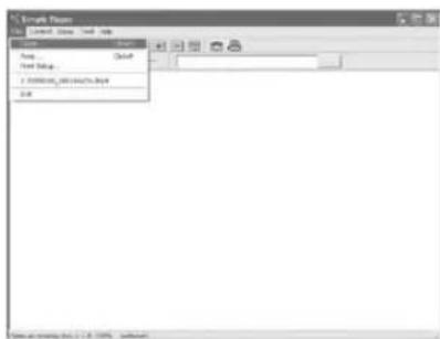
- Select the removable storage and choose one of *.fmp4" file.
- The selected ARCHIVE file is played back.
| Reverse playback Enlarge | | |
| Playback Reduce | | |
| Pause Actual size | | |
| Stop | | Save the present frame as a BMP image |
| To the back frame Print | | |
| To the front frame | Status bar | Display the playback speed. magnification, and information on the storage. |
| Speed control |
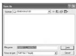
- Snap shot
Save the present image as a bmp file. Select the toolbar. The result will be as follows.

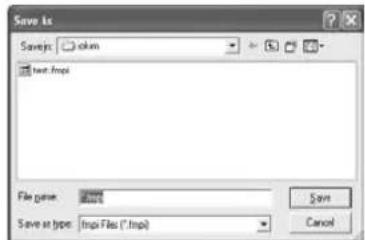
Type in the file name and press Save' to store it as a bmp file.
- Print
Prints the present image. Select in the toolbar.
The result will be as follows..
If you want to print the present image, click OK, other wise, click
Type in the phrase you added in "Description". Then press the "OK" button.
Select Print and press "OK".
The following pages are geared towards advanced users who function as network adminidtrators, and will be using the system in a network environment.
It is an administrator's menu to set the general items on SMT-190DN Server. To use this menu, you need an administrator's ID and Password.
The default Admin. ID is "root" and Admin. password is "root". The password can be changed in Admin. Menu.
1) When you connect to the SMT-190DN Server through Web browser, the initial screen will be as follows.
2) Type in the administrator and password in the user's name and password columns and press Enter key to execute the Admin Menu as shown below.
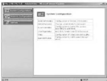
3) Screen configuration
①: General menus of Admin Menu. The menus related to SMT-190DN Server are divided into System, Network, and Utilities in the main menu. Each of them has several sub menus.
②: When you click one of the main menus (System Configuration, Network Configuration, Utilities), its sub menus and simplified explanation on them will appear.
| Category Main Menu |
| System Configuration | System Information |
| Data & Time |
| Admin.Password |
| User Registration |
| Alarm Notification |
| Network Configuration | Network Configuration |
| PPPoE(DSL) |
| Network port |
| View Network Status |
| DDNS Configuration |
| Utilities Save Configuration |
| Reboot |
| System Update |
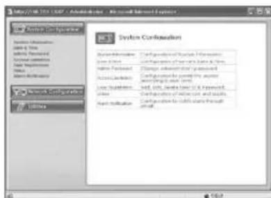
In this menu, you can check the information on the system including the name of the SMT-190DN Server. Server name can be changed if desired.
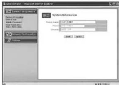
| Server Name Type in the name of the SMT-190DN Server.
• Server's name should be composed of 19 or less numerals or English alphabetical letters.
It cannot start with a numeral and should start with a letter. White characters including a space, tab, and a special letter cannot be used. |
| Model Model name is SMT-190DN . |
| Version SMT-190DN Server product's version |
After completing the set up, click "Apply" button. If you click "Back" button, the initial values are entered in all fields.
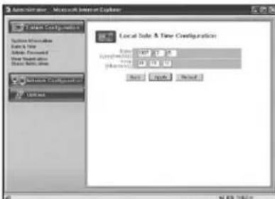
2. Date & Time
Set the display date and current time.
3.Admin.Password
In this menu, the administrator (root) password can be changed.
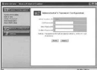
After completing the set up, click "Apply" button. The new password will be applied. The user needs to log in again by using the new password.
| Administrator's ID Administrator's ID is always "root". |
| Old Password The initial password is "root". |
| New Password Type the new password. |
| * The password should be composed of 4-20 digit numerals or alphabets. |
| Confirm Password | Type the new password again. |

Note
Execute the "refresh" for the Remote Viewer after the ID or PW changes.
4. User Registration
This is a user control menu to register, changed or delete the users who may have access to SMT-190DN Server.

| User ID Set the ID you want to register. |
| Password Set the password you want to register. |
| Confirm Password | Type again the password you want to register. |
| Full Name Type in the name you want to register. |
| Add | This is a menu to register a user. It is to fix the user's ID, Password, name, and set the users accessibility to the system.
- Type in the user's ID in the User ID column.
- Type in a password in the Password and Confirm columns. The user's ID and the password should be composed of 20 or less numerals or letters.
- Type in the name of the user in Full Name column. |
| Edit | On this menu, you can change the existing password and name. The user's ID cannot be changed. The configuration of the menu is same as Add, however you should select the user's ID on this menu.
- Choose Edit menu.
- Click "Select User ID" in User ID and click the user's ID you want to edit.
- Modify the password and name and click "Apply" button to apply those changes. |
| Delete | This menu is to delete the registered user.
- Choose Delete menu.
- Choose the user's ID you want to delete in the box.
- Click Delete button to delete the ID. |
After completing the set up, click "Apply" button. If you click "Back" button, the initial values are entered in all fields.

Note
A maximum of 2 users can log onto the system at one time.
USER'S MANUAL
5. Alarm Notification
This notifies the registered users of an alarm arising situation through e-mails. At this time, a maximum of 5 stored JPEG pictures, which were stored, can be sent together.
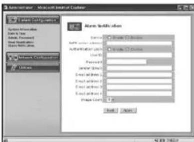
| Service Choose | enable if you want to send the Alarm Notifying E-MAIL. |
| SMTP server address | SMTP server of the ISP that provides SMT-190DN with address services. ISP's confirmation required. |
| Authentication Login | Choose enable if you want to log in the SMTP of the ISP providing SMT-190DN with services. |
| User ID ID for the SMTP server of the ISP that provides SMT-190DN with services. |
| Password Password for the SMTP server of the ISP that provides SMT-190DN with services. |
| Sender (E-mail) | Register the Administrator E-mail SMT-190DN |
| E-mail address 1 ~4 | E-mail addresses you want to send the alarm notification to. |
| Image count FMPI images to send.Up to 5 pictures can be sent at 0.5-second intervals.* Some SMTP servers may not support JPEG for warding.Set this function after checking the SMTP server. | |
After completing the set up, click "Apply" button.
EX) When user who has an e-mail address
(SMT-190DN@yahoo.com) and password(123456) in
YAHOO, sets "Alarm Notification" in order to send a mail to (test1@yahoo.com).
After completing the set up, click "Apply" button.
- Image transfer in your e-mail account.
In the event of Alarm, please use PLAYER to catch normal JPEG images. Otherwise, the image size will be reduced to a half JPEG size. Refer to Eng-32 "How to play" for the detailed usage of PLAYER
1. Network Configuration
On this menu, you can change the general environment details related to the network of the SMT-190DN Server and check the present status.
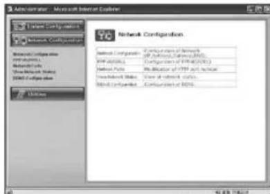
| Network Configuration | Set to "Static IP" or "DHCP" DDNS Configuration: Set DDNS |
| PPPoE(DSL) Set PPPoE (DSL). |
| Network Ports Set "Network Port". |
| View Network Status | Modification of HTTP and other application network port numbers. |
| DDNS Configuration | DDNS Configure |
1-1. Network Configuration : Static IP
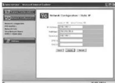
1) If the IP of the SMT-190DN Server is Static : Choose "Static IP".
2) Type in the IP Address you want to assign to the SMT-190DN Server, NetMask, GateWay, DNS1, and DNS2 addresses.
1-2. Network Configuration : DHCP Client

1) If the IP of the SMT-190DN Server is DHCP : Choose "DHCP Client".
2) Type in the addresses of DNS 1 and DNS 2.
3) Click Apply button to apply the settings. If you click Reset button, the latest setting will be applied again.
Click Back button if you don't want to apply the setting.
4) If the mac address of an user is XX:XX:XX:FF:00:00, a user who uses DDNS but does not know the IP can connect the Viewer by typing as follows in the URL. EX) http://wff0000.websamsung.net

MAC Address.
Locate the MAC Address of the SMT-190DN (each SMT-190DN has its own unique MAC address). It can be checked in "5-9) NETWORK SETUP function and setting method of SETUP MENU. It is the last 6 digits as shown below.
MENUSTETUPMENUSTNETWORKSETUP
2. PPPoE (DSL) for Eth0
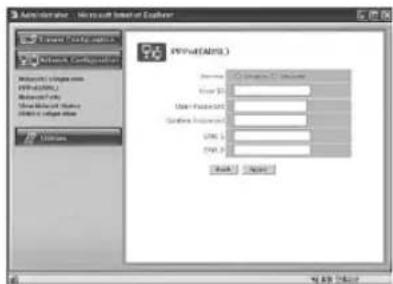
1) Service: Decide if you want to try PPPoE Connection or not.
2)User ID:User's ID that is registered in the ISP.
3)User Password:User's password that is registered in the ISP.
4) Confirm Password : Confirm the password.
5) DNS (Domain Name Service): Service to convert a Domain Name (ex. www.yahoo.com) into an IP address (ex. 216.109.127.28).
The SMT-190DN Server uses this service to join the FTP server or other webs by the Domain Name.
DSL service supports only PPPoE (Point to Point over the Ethernet).
- DNS is a default value, so it does not need to be changed.

Note
When connecting, ID & PASSWORD are limited to 40 characters.
3. Network Ports Configuration
It sets the HTTP Port number to use when the SMT-190DN Server communicates with a Client PC.
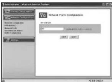
The present SMT-190DN Server uses HTTP Port (80).
- HTTP Port
1) This is the port the Client PC uses to connect to the web page of the SMT-190DN Server. Depending on the environment of the network, its value may vary.
2) The default value is 80 and can be assigned from 1024 to 65535 maximum.
* If you change the value of the HTTP Port, you should type in the new one with the address of the SMT-190DN Server in the address window of the web browser.
(Ex. If the IP address of the SMT-190DN Server is 192.168.1.100 and the HTTP Port :8080, http://192.168.1.100:8080.)
3) Click Apply button to apply the present setting.
CAUTION
Set the port to be used when connecting to SMT-190DN in Internet Explorer. The port setting is used for various network configurations, for example when connecting to a network with firewalls.
4. View Network Status
This is a menu to see the general status of the network setting of the SMT-190DN Server.
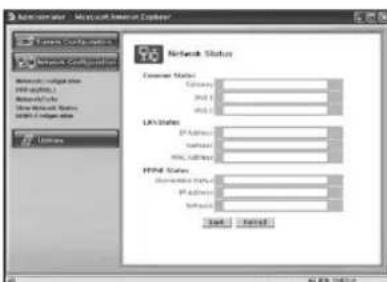
| Common Status | To check the status of the Gateway, DNS 1 and DNS 2. |
| LAN Status | To check the status of the STATIC IP Address, Netmask, and MAC Address. |
| PPPoE Status | If the PPPoE service is connected, the Link is up. At this time, the service IP and NETMASK can also be checked. If the PPPoE service is not connected, the Link is down. The existing setting will be recalled if you press Reload button. |
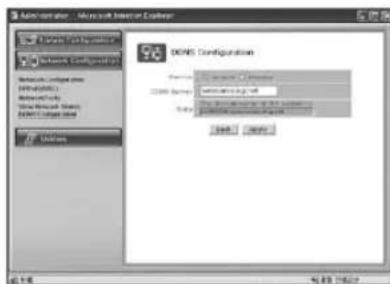
5. DDNS Configuration
| Service Select Enable or Disable |
| DDNS Server | Websamsung.net |
| Note | The domain name of this system is wff0000.websamsung.net |
CAUTION
Since the connection to SMT-190DN is made using domain names (EX: http://wff0000.websamsung.net) that are automatically registered in Samsung's DDNS server when using a DHCP configuration; the IP address, Subnet Mask and Gateway in the Network Tab of Admin Mode do not need to be entered.
8-3-3) Utilities.
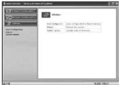
1. Save Configuration
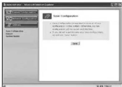
This menu is to save all of the present settings in the Flash Memory. If you changed any of the settings for the SMO-190DN, it is recommended that you save it in the Flash Memory in this menu.
2. Reboot
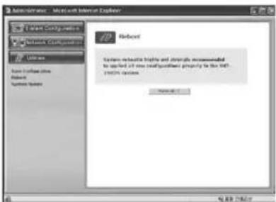
This menu is for the rebooting of the system. It is better to reboot the system if you change the setting and update the flash.
- Click "Reboot" in the utilities group.
- Click "Reboot!!".
3. System Update
This menu is to update the inner programs and data of the SMT-190DN Server. They are recorded in the Flash Memory and composed of 2 parts called System Image and Web Image respectively. Each image file should be stored in the user's PC for update. Depending on the range you want to update, press the start button properly.
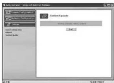
Normal (System and Web) Update the System and Web.
USER'S MANUAL
3-1. Normal (System and Web) Update
When you click the start button located in the bottom of Normal (System and Web) Update, a window will appear to ask if you want to update.

Click "Cancel" to stop updating. Click "OK" to proceed updating.
A pop-up window will appear for the file searching process for the System Image Update.
Choose "fw-dvr.tar.gz" in the browser.
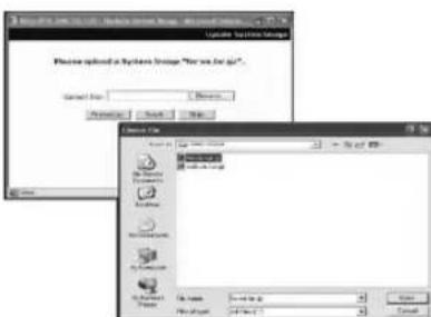
Click "Next" button to move to the next stage.
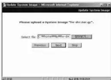
Click "Skip" button to move to the next stage without System Image's update.
Click "Next" button and a window will appear to check the name and size of the file.
Click "Previous" button to go back to the previous stage.
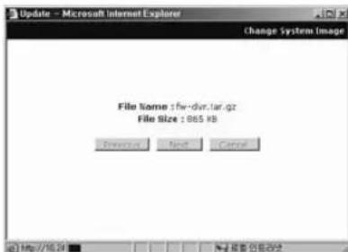
Click the "Next" button to execute updating of the program and move to the next stage.
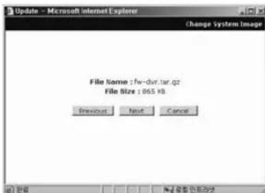
Don't turn off the monitor during this stage and wait for complete update.
In the next stage, a pop-up window will appear for the file searching process for the Web Image Update.
Choose "web-dvr.tar.gz" in the browse.
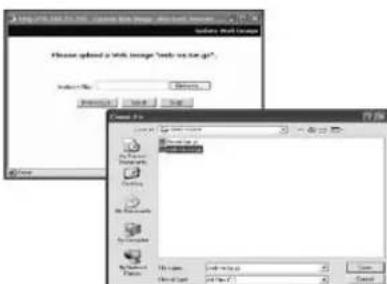
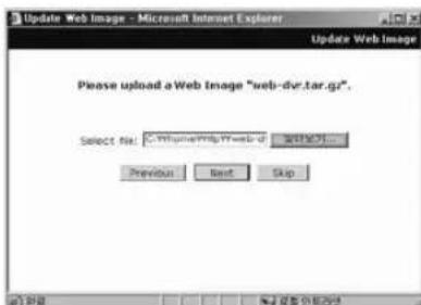
USER'S MANUAL
Click "Skip" button to move to the next stage without Web Image's update.
Click "Next" button and a window will appear to check the name and size of the file.
Click "Previous" button to go back to the previous stage.
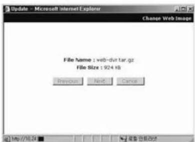
Click the "Next" button to execute updating of the program and move to the next stage.
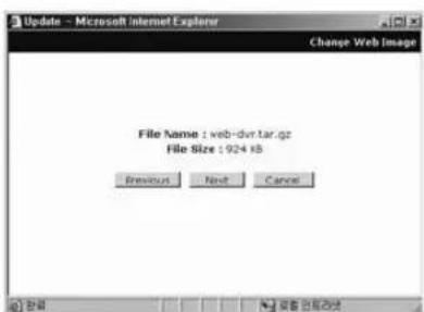
Don't turn off the monitor during this stage and wait for complete update.
After completing the update, click the "Reboot" button to reboot the system.
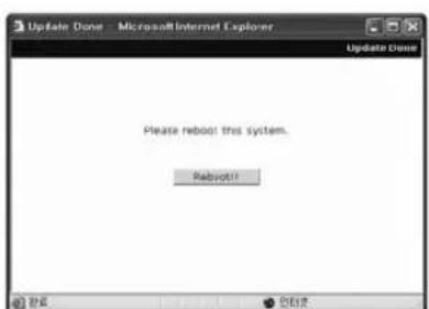
Click the "Reboot" button and press the confirmation button to reboot the system.
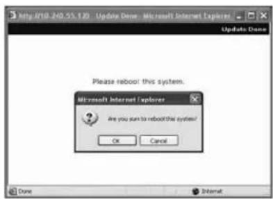
Close your web browser and wait for about a minute before you log in again.
Chapter 9 : Functions
9-1) FREEZE KEY
(REMOTE CONTROLLER)
If the "FREEZE" key is pressed, the "II" Marker is displayed at the top right screen and the screen is frozen. Press the "FREEZE" key again to make the "II" Marker disappear and cancel the FREEZE function.
9-2) ZOOM MODE DISPLAY (REMOTE CONTROLLER)
When users want to see a zoomed image of a specific area of the display, press the ZOOM KEY to display the selected area. Select the targeted zoom area by using / , / KEY and press the ENTER SWITCH, then the selected area will be displayed at full single mode with zoomed area doubled. When Zoom is used in SINGLE DISPLAY MODE (CH2), the operation will be carried out as shown in figure below. (You can select nine Zoom areas on the screen in SINGLE DISPLAY MODE.)
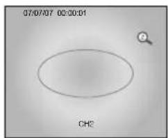
CH2 SINGLE DISPLAY
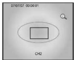
Press ZOOM KEY
ZOOM area is activated.
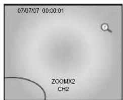
The selected area will be doubled and at FULL DISPLAY.
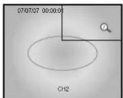
Press ENTER KEY
Press 4 KEY, and move to desired location
9-3) PIP MODE DISPLAY (REMOTE CONTROLLER)
PIP Mode Display is used to view the PIP screen in Single screen mode. If you press SEQUENCE, the PIP Sub- screen will change. If you press the KEY, the sub screen can be transferred to another channel. Sub-screen location can be selected in CLOCK/DISPLAY MENU in SETUP MENU.

PIP DISPLAY


Main and Sub screen is switched
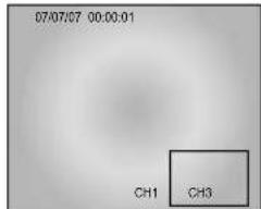
PIP DISPLAY


Main screen is switched

Single screen display
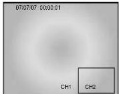
PressPIP KEY
Main and Sub screen is displayed as set in the DISPLAY MENU of SETUP MENU
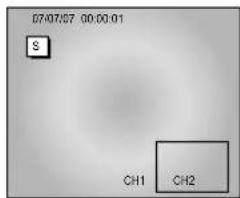
PIP DISPLAY

Press SEQUENCE KEY
Sub screen is switched
Initial display mode of monitor is 9 splits. If you want to see the camera image at full mode, select a target camera by using the CHANNEL KEY. After that, press the ENTER SWITCH and selected camera image will be displayed at full screen. If you press the / or / KEY SINGLE DISPLAY MODE at this time, you can see another camera image at full screen. For example, when you want to see CH1 at FULL MODE after SINGLE -displaying CH2 at 9 splits, please follow the instructions below.
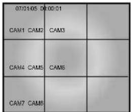
INITIAL DISPLAY STATUS

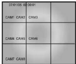
Select CH1 by using CHANNEL KEY


FULL SCREEN DISPLAY OF CH2

Press CH2 KEY.

FULL SCREEN DISPLAY OF CH1
9-5) QUAD MODE DISPLAY
Users can switch SINGLE DISPLAY MODE and SEQUENTIAL DISPLAY MODE to QUAD DISPLAY MODE, or QUAD-A (QUAD-B) to QUAD-B(QUAD-A) or PIP MODE to QUAD MODE. Press the QUAD/PAGE KEY.
- QUAD MODE display from SINGLE MODE or SEQUENCE MODE.

CH1 DISPLAY

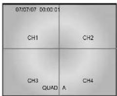
QUAD MODE DISPLAY of QUAD-A
- QUAD B(QUAD A) display from QUAD A(QUAD B),
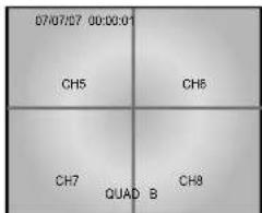
QUAD MODE DISPLAY of QUAD-B

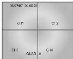
QUAD MODE DISPLAY of QUAD-A
9-6) AUTOSEQUENTIAL DISPLAY MODE (FRONT PANEL KEY)
Pressing the SEQUENCE KEY allows Single or Quad mode screens to automatically switch.
If the DWELL TIME SETTING of SETUP MENU is set to 3 seconds and the SEQUENCE
KEY is pressed, the operation will be carried out as follows.
\* SINGLE MODE SEQUENCE DISPLAY

Press SEQUENCE KEY when CH2 is displayed at full screen

In 3 seconds
Automatic sequential switching to CH3
In 3 seconds

Automatic sequential switching to CH5

In 3 seconds
Automatic sequential switching to CH4
* QUAD MODE SEQUENCE DISPLAY
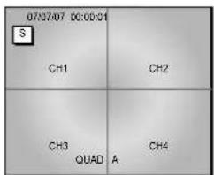
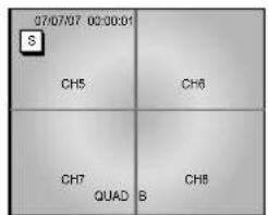
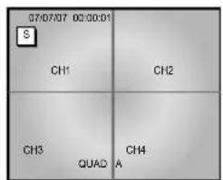
9-7) LIVE/PB/TRIPLEX KEY (REMOTE CONTROLLER)
PB screen at the top of screen and LIVE screen at the bottom of screen are output at the same time.
| 07/07/07
CH1 CH2 | 00:00:01
CH3 CH4 | | |
| CH5 CH6 | CH7 CH8 | | |
| PB1 PB2 | PB3 PB4 | | |
| PB4 PB5 | PB7 PB8 | | |
No Signal Display
When there is no connection at the VGA input, the On Screen Display will show this message.


Press DVR/LCD button to select LCD MENU or DVR MENU by turns. If DVR/LCD LED is green, it means LCD mode. if it is red, it is DVR mode.
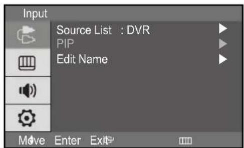
Inputs can be set to VGA mode.
- Press the MENU and ENTER button.
- Press the ENTER or button and then / button to select input menu.
- Press the ENTER or button to save the setting and exit.
PIP ON (VGA mode only)
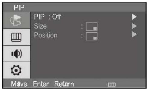
If you didn't select VGA input, this menu is not available.
- Press the MENU and ENTER button.
- Press the / and ENTER button to select the PIP menu.
- Press the ENTER or button to see the sub menu.
- Press the / and ENTER button to select On.
- Press the MENU or button repeatedly to exit.
PIP Size select (VGA mode only)
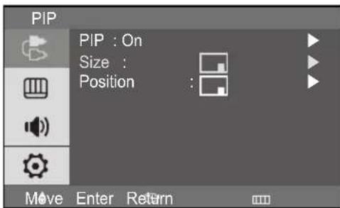
If you didn't select PIP On, this menu is not available.
- Press the MENU and ENTER button.
- Press the / and ENTER button to select the PIP menu.
- Press the / and ENTER button to select the Size.
- Press the / and ENTER button to select setting. (or
- Press the MENU or button repeatedly to exit.
PIP Position select (VGA mode only)
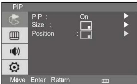
If you didn't select PIP On, this menu is not available.
- Press the MENU and ENTER button.
- Press the / and ENTER button to select the PIP menu.
- Press the / and ENTER button to select the Position.
- Press the / and ENTER button to select setting. (
- Press the MENU or button repeatedly to exit.
PIP OFF (VGA mode only)
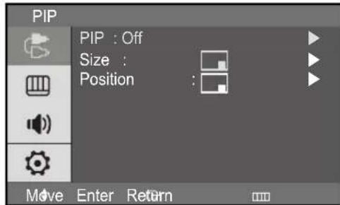
If you didn't select VGA input, this menu is not available.
- Press the MENU and ENTER button.
- Press the / and ENTER button to select the PIP menu.
- Press the ENTER or button to see sub menu.
- Press the / and ENTER button to select the Off.
- Press the MENU or button repeatedly to exit.
Edit Name
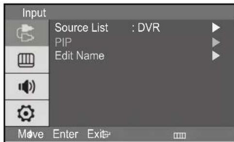
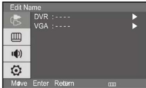
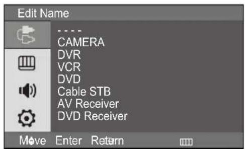
- Press the MENU and ENTER button.
- Press the / and ENTER button to select the Edit menu.
- Press th / and ENTER button to select input.
- Press the / and ENTER button to select the Name you want.
- Press the MENU or button repeatedly to exit.
DVR Mode
Mode:Dynamic,Standard,Movie,Custom
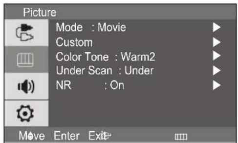
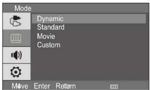
- Press the MENU and / button to select the Picture menu.
-
Press the ENTER or button to select the Mode menu.
-
Press the ENTER or button.
- Press the / button to select the mode you want. (Dynamic, Standard, Movie, Custom)
- Press the MENU or button repeatedly to exit.
Custom
DVR mode : Contrast, Brightness, Sharpness, Color
VGA mode : Contrast, Brightness, TINT(option)
- Tint feature is enabled while input signal is NTSC mode.
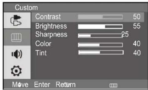
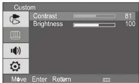
- Press the MENU and / button to select the Picture menu.
- Press the ENTER or button to select the Custom menu. (Press / button to select the custom -Video mode)
- Press the ENTER or button to see the sub menu.
- Press the / and ENTER button to select the setting you want.
- Press the and the ENTER button to adjust the setting value and save.
- Press the / button to select the Contrast or Brightness.
- Press the and ENTER button to adjust the setting value and save.
- Press the MENU or button repeatedly to exit.
USER'S MANUAL
If you select the Brightness, then the picture below appears on the screen.

Color Tone
DVR mode: Cool2, Cool1, Normal, Warm1, Warm2
- Tint feature is enabled while input signal is NTSC mode.