
SHR1041K - Surveillance Camera SAMSUNG - Free user manual and instructions
Find the device manual for free SHR1041K SAMSUNG in PDF.
| Product Type | 4-Channel Digital Video Recorder (DVR) with Cameras |
| Brand | Samsung |
| Model | SHR1041K |
| Number of Video Channels | 4 (BNC and RJ-11 inputs) |
| Maximum Recording Resolution | 704 x 480 (D1) |
| Video Compression Format | MPEG-4 |
| Storage Capacity | 250 GB Internal (SATA), Expandable up to 500 GB |
| Recording Modes | Continuous, Motion Detection, Alarm, Manual, Scheduled |
| Network Functions | Remote Monitoring, Remote Search, DDNS, DHCP |
| Network Connectivity | Ethernet 10/100Base-T (RJ-45) |
| Video Output Ports | Composite (CVBS) 1 channel, VGA 1 |
| Audio Inputs | 4 channels via cameras with microphone (RJ-11) |
| Audio Output | 1 channel RCA |
| Motion Detection | 4 channels, adjustable sensitivity from 1 to 10 |
| Power Supply | DC 12V / 4A (power adapter included) |
| Power Consumption | 20 W |
| Operating Temperature | 0°C to 40°C |
| Dimensions (Main Unit) | 290 x 307 x 58 mm |
| Weight (Main Unit) | 2.55 kg |
| Included Cameras | 1 standard camera and 1 night vision (infrared) camera with 3.8 mm lens |
| Included Accessories | Remote control, PS/2 mouse, power adapter, cables, camera mounts |
| Security | User and administrator password protection, digital watermark |
| Maintenance and Cleaning | Clean only with a dry cloth; do not use liquid |
| Spare Parts and Repairability | Contact a qualified technician or an authorized Samsung dealer |
Frequently Asked Questions - SHR1041K SAMSUNG
User questions about SHR1041K SAMSUNG
0 question about this device. Answer the ones you know or ask your own.
Ask a new question about this device
Download the instructions for your Surveillance Camera in PDF format for free! Find your manual SHR1041K - SAMSUNG and take your electronic device back in hand. On this page are published all the documents necessary for the use of your device. SHR1041K by SAMSUNG.
USER MANUAL SHR1041K SAMSUNG
4 Channel DVR User Manual
imagine the possibilities
Thanks you for purchasing this Samsung product.
To receive a more complete service, please
register your product at
www.samsungsecurity.com
Features
This product enables you to record 4 channels of camera image and voice source simultaneously. This feature provides an excellent picture quality for both real time monitoring and search.
- You can also monitor remote videos or search for your previous recordings and change the menu settings of the DVR via the network.
- As this product can bypass the Windows operating system to implement the DVR-specific operating system on its hardware components, the overall operation is stable.
- This product compresses the 4 channels of camera input into a format of MPEG-4 before converting analog to digital video, which enables you to make an effective use of your hard disk.
- You can use the remote control, mouse, search buttons on the front panel or a combination of them to perform freeze, fast playback, backward playback as well as monitoring an event of detection such as time, motion and alarm.
- It provides various recording modes including continuous, motion and alarm recordings.
Supports DDNS (use dynamic IP as like static IP) - USB Back Up
- Separate resolution settings for each channel
- Separate motion area settings for each channel
Supports a triplex tasking of Save and Remote View during a search.
Motion Detection Recording - Prevents unauthorized user control and data loss using the password system
Supports operations of the remote control and mouse
Ordinary BNC or DIY camera are supported
Real time recording in high quality and high frame rate (up to 30 frames: Based on 352× 240 - Record and play in high quality (based on 704 × 480 )
High/low speed search (search list/speed search) - Integrated alarm buzzer
- Continuous recording in HDD Overwrite mode
Read these operating instructions carefully before using the unit.
Follow all the safety instructions listed below.
Keep these operating instructions handy for future reference.
1) Read these instructions.
2) Keep these instructions.
3) Heed all warnings.
4) Follow all instructions.
5) Do not use this apparatus near water.
6) Clean only with dry cloth.
7) Do not block any ventilation openings, Install in accordance with the manufacturer's instructions.
8) Do not install near any heat sources such as radiators, heat registers, stoves, or other apparatus (including amplifiers) that produce heat.
9) Do not defeat the safety purpose of the polarized or grounding-type plug. A polarized plug has two blades with one wider than the other. A grounding type plug has two blades and a third grounding prong. The wide blade or the third prong are provided for your safety. If the provided plug does not fit into your outlet, consult an electrician for replacement of the obsolete outlet.
10) Protect the power cord from being walked on or pinched particularly at plugs, convenience receptacles, and the point where they exit from the apparatus.
11) Only use attachments/accessories specified by the manufacturer.
12) Use only with the cart, stand, tripod, bracket, or table specified by the manufacturer, or sold with the apparatus. When a cart is used, use caution when moving the cart/apparatus combination to avoid injury from tip-over.
13) Unplug this apparatus during lightning storms or when unused for long periods of time.
14) Refer all servicing to qualified service personnel. Servicing is required when the apparatus has been damaged in any way, such as power-supply cord or plug is damaged, liquid has been spilled or objects have fallen into the apparatus, the apparatus has been exposed to rain or moisture, does not operate normally, or has been dropped.
BEFORE START
This user's manual provides Information for using DVR such as brief introduction, part names, functions, connection to other equipment, menu setup, and the like.
You have to keep in mind the following notices:
SEC retains the copyright on this manual.
- This manual cannot be copied without SEC's prior written approval.
- We are not liable for any or all losses to the product incurred by your use of non-standard product or violation of instructions mentioned in this manual.
- If you want to open the case of your system for checking problems, please consult the expert from the shop where you bought the product.
- You may download open source codes from the following website: www.samsungsecurity.com.
- Before installing any external device such as external memory or HDD, please check the compatibility of the device with Samsung DVR. The list of the compatible devices with Samsung DVR can be obtained from your vendor.
- Apparatus shall not be exposed to dripping or splashing and no objects filled with liquids, such as vases, shall be placed on the apparatus.
- The Mains plug is used as a disconnect device and shall stay readily operable at any time.
Warning
Battery
Exchanging a wrong battery in your product may cause an explosion. Therefore you must use the same type of battery as the one being used in the product.
The following are the specifications of the battery you are using now.
Normal voltage: 3V
Normal capacity: 220mAh
Continuous standard load: 1.1uA
- Operating temperature: -20^ +85^ (-4^ +185^)
CALIFORNIA USA ONLY
This Perchlorate warning applies only to primary CR (Manganese Dioxide) Lithium coin cells in the product sold or distributed ONLY in California USA.
"Perchlorate Material - special handling may apply,
See www.dtsc.ca.gov/hazardouswaste/perchlorate."
System Shutdown
Turning off the power while the product is in operation, or taking not permitted actions may cause damage to the hard drive or the product. Also it can cause a dysfunction to the hard disk while using the product.
Please turn off the power using the Power button on the front of your DVR.
After selecting <OK> in the pop-up menu, you can pull off the power cord.
You may want to install a UPS system for safe operation in order to prevent damage caused by an unexpected power stoppage. (Any questions concerning UPS, consult your UPS retailer.)
Operating Temperature
The guaranteed operating temperature range of this product is 0^ 40^ ( 32^ 104^ ).
This product may not work properly if you run right after a long period of storage at a temperature below the guaranteed one.
When using the device after a long period of storage at low temperature, place the product at room temperature for a while and run it.
Especially for the built-in HDD in the product, its guaranteed temperature range is 5^ 55^ ( 41^ 131^ ).
Likewise, the hard drive may not work at a temperature below the guaranteed one.


This equipment has been tested and found to comply with the limits for a Class A digital device, pursuant to part 15 of the FCC Rules. These limits are designed to provide reasonable protection against harmful interference when the equipment is operated in a commercial environment.
This equipment generates, uses, and can radiate radio frequency energy and, if not installed and used in accordance with the instruction manual, may cause harmful interference to radio communications. Operation of this equipment in a residential area is likely to cause harmful interference in which case the user will be required to correct the interference at his own expense.
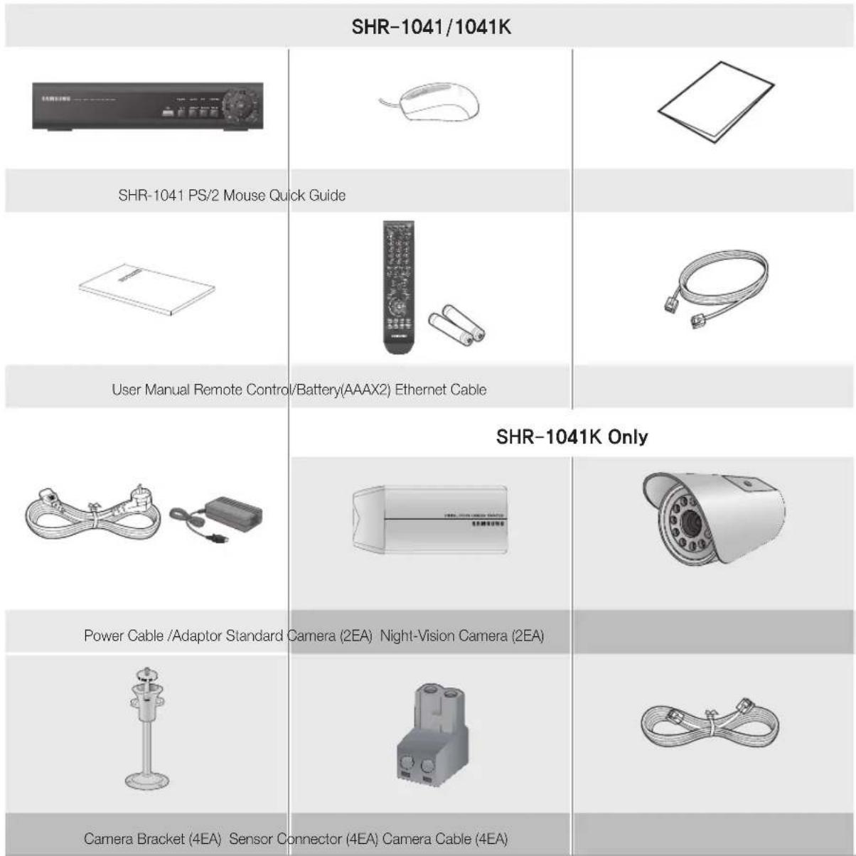
Package Contents
Please unwrap the product, and place the product on a flat place or in the place to be installed. Please check the following contents are included in addition to the main unit.
contents
overview

2 Features
3 Important Safety Instructions
4 Before Start
6 Contents
installation

8 Part Names and Functions (Front)
9 Part Names and Functions (Rear)
10 Remote Controller
11 Standard Camera
12 Night-Vision Camera
13 Camera Bracket
14 Connecting with other Device
getting started

17 Starting the System
17 Login
Live

18 Icons on the Live Screen
19 Live Screen Menu
search

21 Search
23 Archiving

settings
24 System Setup
24
40 Record
weB viewer
44
44 Introduction
44 Connecting Web Viewer
46 Connecting DVR
48 Using Live Viewer
50 Remote Setup
52 Search
appendix
56
56 Product Specification
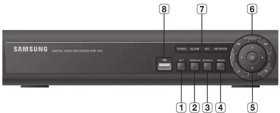
PART NAMES AND FUNCTIONS (FRONT)
| Part Names Functions | ||
| 1 | POWER Used to turn on or off the system. | |
| 2 | DISPLAY | Each time you press in Live mode, the screen will be switched in the sequence of 4-split, Single and Auto Sequence in order. |
| 3 | SERACH Goes to the search screen. | |
| 4 | MENU Goes to the system menu screen. | |
| 5 | DIRECTION ENTER | ▲▼▲▶: Used to select a system menu item. ▲: Selects and runs a menu item. |
| 6 | SPEED PLAYBACK | ▶: Used for quick forward playback. |
| ←: Used for quick backward playback. | ||
| FREEZE RETURN | II: Freezes the screen or resumes playing. | |
| : Used to move one level up in the menu screen. | ||
| 7 | LED | NETWORK: Displays both network connection and data transfer status. |
| REC: Flashes while the recording is in progress. | ||
| ALARM: Flashes if an event occurs. | ||
| POWER: Displays the status (ON/OFF) of power connection. | ||
| 8 | USB PORT Used to connect a USB storage device. | |
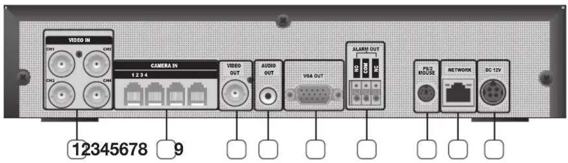
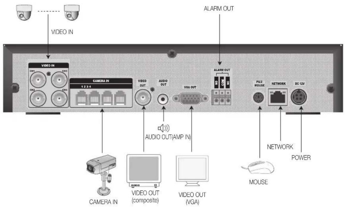
| Part Names Functions | |
| 1 | VIDEO IN Composite video signal input port (BNC type port). |
| 2 | CAMERA IN RJ-11 port for camera input. |
| 3 | VIDEO OUT Composite video signal output port (BNC type port). |
| 4 | AUDIO OUT Audio signal output port (RCA jack). |
| 5 | VGA OUT Video output port for video output to a VGA monitor. |
| 6 | ALARM OUT Alarm output port |
| 7 | PS/2 MOUSE PS/2 type mouse connection port. |
| 8 | NETWORK RJ-45 port for network connection. |
| 9 | DC INPUT (DC12V) Power connection port for 12V/4A adaptor |
REMOTE CONTROLLER

Changing the remote control ID
In a multi-DVR system using a single remote control, you can control only the DVR that matches the ID that you have set using the ID button.
- Press the ID button to check the ID of each of "IR REMOTE CONTROLLER" and DVR.
The defaults are 00 for the SYSTEM ID and 00 for the REMOTE ID, respectively.
The REMOTE ID and the SYSTEM ID can only be checked in Live mode.
- To change the REMOTE ID of the IR REMOTE CONTROLLER, press and hold the ID button while entering a desired combination of two digits from 00 to 99.
- To change the ID of the DVR, refer to "CONTROL DEVICE > SYSTEM ID". (Page 36)
- Press the ID button of the "IR REMOTE CONTROLLER" to check the ID.

If the system number defined in "CONTROL DEVICE" is different from the number specified using the remote control, no other button than the [ID] buttons will operate.
A surveillance camera is provided in addition to the main unit. Check the installation steps and the features of each camera.
Camera Part Names
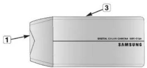
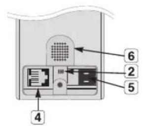
Lens : Focal length of 3.8mm enables you to cover relatively longer range of monitoring.
2 Microphone: Transfers the onsite sound to the monitor.
3 Camera fitting groove : Groove that is used to fit the camera bracket. There exist two grooves; one on the top and one on the bottom.
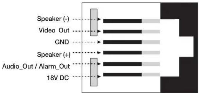
4 6-pin modular jack: Connects the camera to the monitor. See "Pin Setting" for the connection.
5 Sensor jack: Connects the sensor to the camera.
6 Speaker: Transfers out the audio signal incoming from the monitor.
Pin Setting
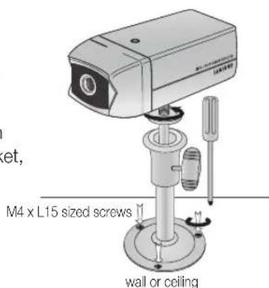
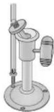
Installing the Camera
The camera can be installed on the wall, ceiling, shelf or a desired position using the provided bracket.
- Select a position where you want to install the camera.
Make sure the selected position can sustain the weight of the camera. - Use the screw bolts (M4 X L15) to mount the camera bracket onto the wall or ceiling.
- Place the camera on the selected position and fit the hole either on the top or the bottom of the camera into the fixing bolt of the bracket, and turn the camera clockwise.
NIGHT-VISION CAMERA
Equipped with the IR LED and the illumination sensor, enables you to monitor at night as well as in daytime. You can also use it indoors as well since it is designed for outdoor use.
Camera Part Names
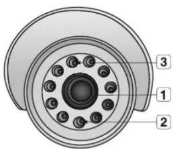
Lens : Focal length of 3.8mm enables you to cover relatively longer range of monitoring.
2 Illumination Sensor: Detects incoming light to control the IR LED.
3 IR LED : This is an infrared LED that is controlled by the illumination sensor.
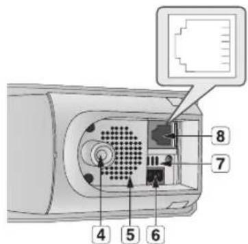
4 Camera fitting groove : Groove that is used to fit the camera bracket. There exist two grooves; one on the top and one on the bottom.
5 Speaker: Transfers out the audio signal incoming from the monitor.
6 Sensor jack: Connects the sensor to the camera.
7 Microphone: Transfers the onsite sound to the monitor.
6-pin modular jack: Connects the camera to the monitor. See "Pin Setting" for the connection. (page 11)
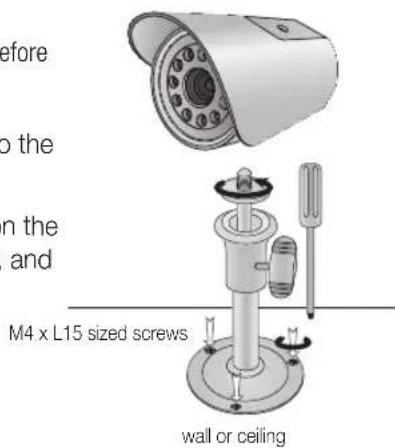
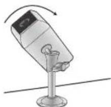
Installing the Night-Vision Camera
The camera can be installed on the wall, ceiling, shelf or a desired position using the provided bracket.
-
Select a position where you want to install the camera.
-
A place where it can tolerate 5 times of the total weight of the camera before installing.
-
Use the screw bolts (M4 X L15) to mount the camera bracket onto the wall or ceiling.
- Place the camera on the selected position and fit the hole either on the top or the bottom of the camera into the fixing bolt of the bracket, and turn the camera clockwise.
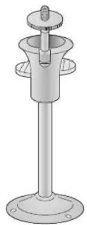
The camera bracket can be used to install the camera on the wall, ceiling or shelf.
Camera Bracket Specification
| Use Indoor | |
| Installation | Wall or Ceiling |
| Dimensions | 57(W) x 47.2(H) x 100.5(L) mm/ 2.25(W) x1.86(H) x 3.95(L) inch |
| Weight | 130g (0.29 lbs) |
| Operating Temperature | -10°C ~ 50°C (14°F ~ 122°F) |
| Accessories | Screw (M4 X L15) : 3 pcs |
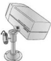
Adjusting the Camera Bracket
- Choose an installation site that can sufficiently support the weight of the equipments to be installed.
- Attach the camera bracket to the wall using the supplied screws (M4 X L15). 4x15 sized screws wall or ceiling.
- Adjust the camera to target the video location and tighten the camera bracket handle on the camera bracket. Install the camera on to the male screw of the camera bracket by rotating the camera in clockwise.
- Loosen the handle by turning it in counter clockwise direction and then adjust the camera position. Tighten the handle, turning it clock wise, and lock the camera in position.
- Connect the camera cable to the camera.
Handle
CONNECTING WITH OTHER DEVICE
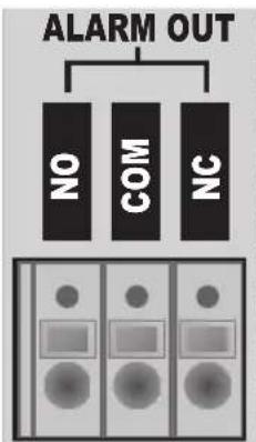
Connecting Alarm Output and Relay
If activated, the alarm will output through the ALARM OUT port on the rear panel. Check the relay output type (Normal Open/Normal Close) and connect to the appropriate port (NO/NC).
- NO(Normal Open): Sensor is open in normal condition, it generates alarm if the sensor is closed.
COM: Connect the grounding cable. -
NC(Normal Close): Sensor is closed in normal condition, it generates alarm if the sensor is open by interruption.
Related Load -
AC:125V0.5A
-DC:30V1.0A
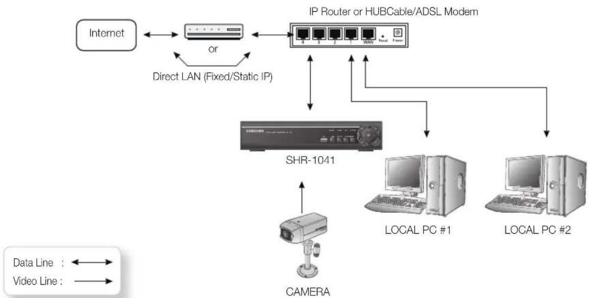
- Connect LAN cable of Cable/ADSL modem or Direct Fixed/Static IP LAN Line to WAN port of IP Router.
- Connect LAN ports of IP Router to Ethernet port SHR-1041 to be set up and to Ethernet port of Local PC to use during setup.
- Connect Video cable of Camera to Monitor.
- Turn on the Monitor power.
If you have a Static (Fixed) IP line or Dynamic IP line (Cable Modem or ADSL Modem) with one IP address (whether its dynamic or fixed), but have more than one internet device to use (such as a PC and a SHR-1041 or several SHR-1041); you must use an IP Router (different from a simple Network Hub); You must set up the Router to work with the SHR-1041 and you must use a network capable PC within The local Router network to do the setup.
If you are using an existing Router which is already set up, you may not need to redo the basic setup of the Router again, but it is highly recommended that you at least read all the instructions below and go through the steps. Whether you are using an existingRouter or a newRouter, you must go through the Port Forwarding portion of the setup.
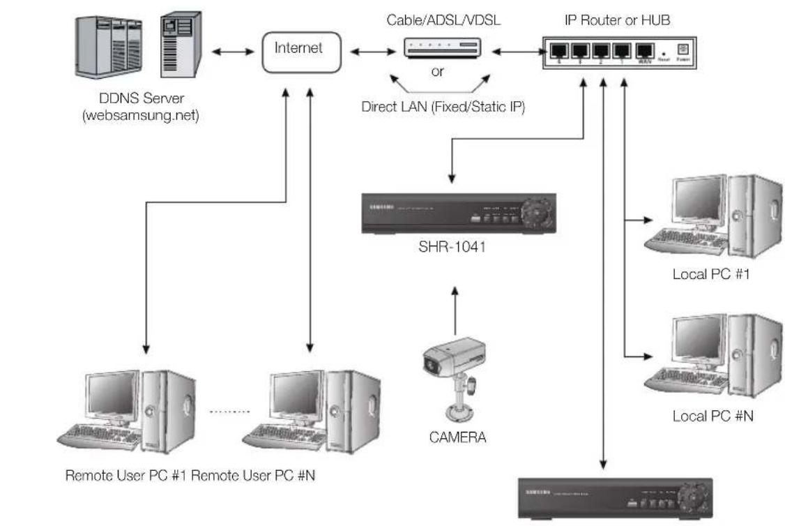
Connecting the Network
You can use the 10/100 Mbps Ethernet connector on the product to connect to the network.
Connecting to the network enables you to perform various functions including remote monitoring, remote search and remote control.

SHR-1041
getting started
starting the system
- Connect the power cable of the DVR to the wall outlet.
- You will see the initialization screen. The initialization process may take a while, depending on the condition of the DVR.
- The Live screen appears.


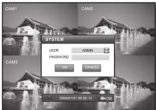
Login
To access a DVR or restricted menu, you should have logged in to the DVR.
- If you start the system or try to access restricted menus, the login dialog pops up.
Double-click any area on the screen or press the [ENTER] button on the front panel to display the virtual keyboard. (Page 26)
- Select a user and enter the password.
The default admin password is "4321".
- Select
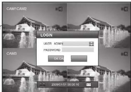
If you have successfully logged in, the Live screen appears.
The default screen is in 4-split mode with an option of continuous recording.
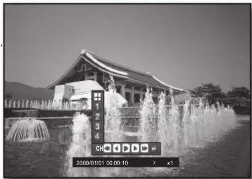
The icons on the Live screen indicate the status of the system.
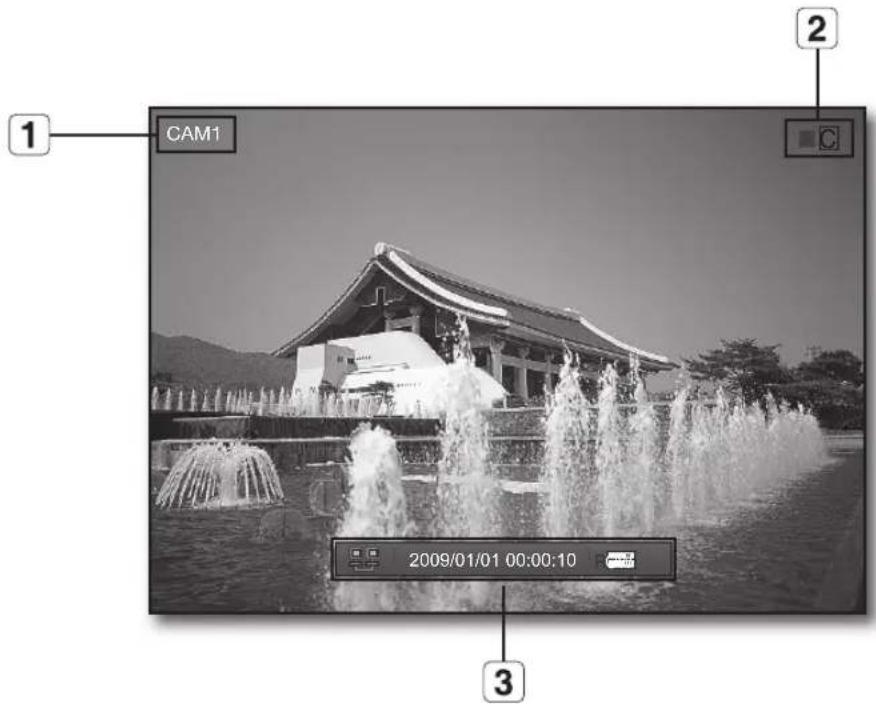
| Name Description | |||
| 1 | Camera Name Displays the name of the camera. | ||
| 2 | Recording Modes | C | Indicates continuous recording. |
| A | Indicates alarm recording. | ||
| M | Indicates motion detection recording. | ||
| P | Indicates manual recording. | ||
| ■ | This box will turn green if an event recording is scheduled. | ||
| 3 | Status Bar | Displays the network connection status. | |
| 2009/01/01 00:00:10 | Displays the current time and date. | ||
| R | Displays the current operation of RECORD, HDD status and OVERWRITE setup. | ||
| To hide the status bar, set it to <OFF> in “SYSTEM SETUP>Display”. (Page 24) | |||
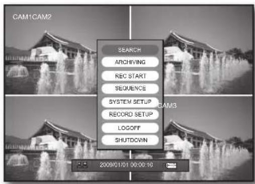
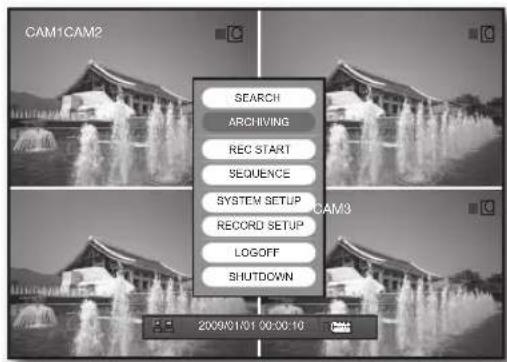
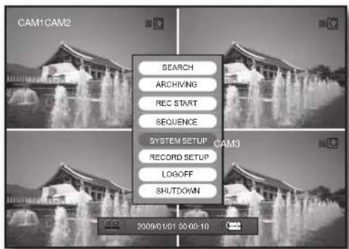
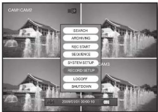
In Live mode, right-click any area or press the [MENU] button on the remote control to display the Live menu.
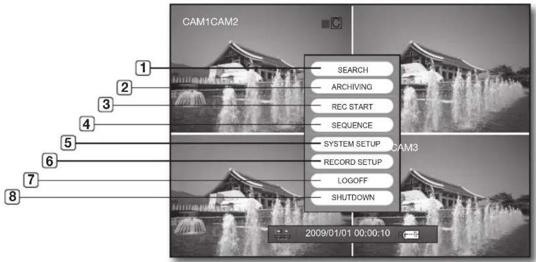
| Name Description | ||
| 1 | SEARCH | Searches for and plays recording data.Refer to “SEARCH”. (Page 21) |
| 2 | ARCHIVING | Searches for a backup device and perform the backup for each channel or at a desired time.Refer to “ARCHIVING”. (Page 23) |
| 3 | REC START/STOP Starts/stops manual recording. (Page 43) | |
| 4 | SEQUENCE | The screen will switch to Sequence mode.Refer to “SEQUENCE”. (Page 20) |
| 5 | SYSTEM SETUP | You can confi gure the settings related to the system screen, camera name, sound, event and storage.Refer to “SYSTEM SETUP”. (Page 24) |
| 6 | RECORD SETUP | You can confi gure the settings of scheduled recording and adjust the picture quality.Refer to “RECORD SETUP”. (Page 40) |
| 7 | LOGOFF | Restricts access to any other menu than REC START/ STOP and SEQUENCE.Refer to “LOGOFF”. (Page 20) |
| 8 | SHUTDOWN The system will shut down. (Page 4) | |
Sequence
The screen will switch to Sequence mode.
- Press the [MENU] button on the front panel or right-click any area.
- Select
.
The screen will switch to Sequence mode.
- Double-click any area or select
again to stop Sequence mode. Double-click it again to switch back to split mode.
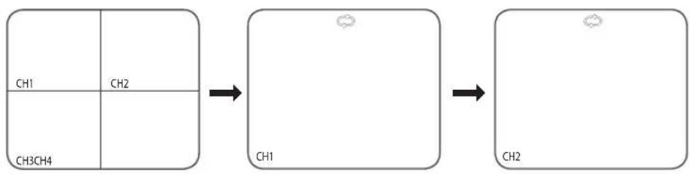
Press the [DISPLAY] button on the front panel or the [VIEW] button on the remote control to switch the mode to Split - Single-Sequence in sequence.
Logoff
Restricts access to the system functions.
- Press the [MENU] button on the front panel or right-click any area.
- Select
You will see the "LOG OFF" dialog.
- Select one from
and .
You will see the confirmation window.
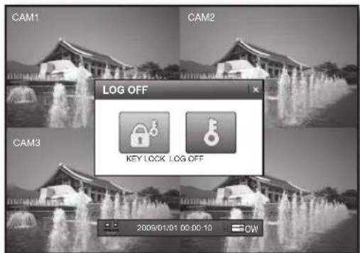
KEY LOCK
Restricts use of buttons on the remote control and the front panel, and access to the Live menu.
If you try to use a button on the front panel or the remote control, or access to the Live menu when you have set
To release the KEY LOCK, enter the password.
LOGOFF
Restricts access to SEARCH / ARCHIVING / SYSTEM SEPUP / RECORD SETUP / SHUTDOWN except for REC START and SEQUENCE.
If you select
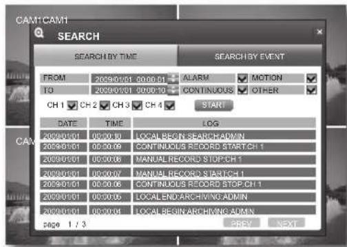
search
You can perform the search for recorded data by the time or by the search criteria such as an event.
SEARCH
Using the mouse may help easier selection of related items.
- In Live screen, right-click any area.
The applicable menu appears.
- Click
in the menu or press [SEARCH] on the remote control or the front panel.
You will see the "LOGIN" dialog.
You will see two options:
One cell in the time bar is equal to 15 minutes.
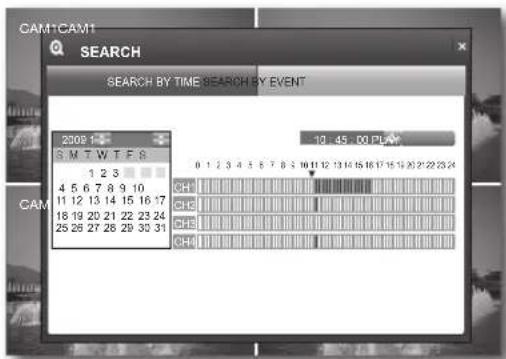
Search by Time
You can search for recording data on a specific date or time.
Using the mouse may help easier selection of related items.
- Use the direction buttons ( ) to select a specific date and press the [ENTER] button.
If any recording data is found for the search date, the recording portion in the time bar of each channel on that specific time will be highlighted blue.
- Set the date or time and select
.
The selected data will be played.
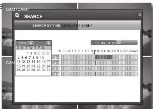
- In a split screen, data of the selected channel will be played. Use the play button bar on the bottom to adjust the speed.
- Using the play button bar
When playback of the recoding data ends, a message of END OF VIDEO is displayed on the screen and a mark of <]> is displayed in the status bar.
- CH: Displays a list of channels available where you can switch the channel.
(4-split, Channel 1, 2, 3, 4) - : Plays backward in the following speed: (X2, X4, X8, X16, X32, X64) Reduces the speed in forward playback.
- : Plays backward.
- 1 : Starts or pauses playing temporarily.
Plays forward. - : Plays forward in the following speed: (X2, X4, X8, X16, X32, X64)
Reduces the speed in backward playback.
: Returns to the previous screen.
- To return to the previous screen, press the [RETURN] button on the remote control or the [ ] button on the front panel.
Search by Event
Select one from ALARM, MOTION, CONTINUOUS, OTHER and period for each channel to display information about the related data.
Using the mouse may help easier selection of related items.
- Use the direction buttons ( ) to select a channel event or period.
- Press
to start the search. Information of DATE, TIME and LOG of the recording period will be displayed. - Double-click a desired item or use the direction buttons ( ) to select one and press the [ENTER] button. The selected data will be played.
backup
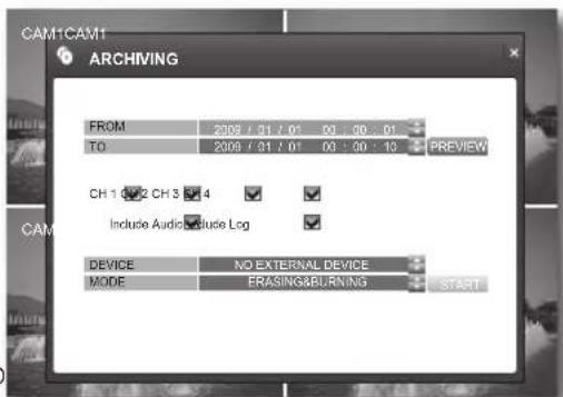
You can check the backup data size and perform backup of a desired channel or at a desired time.
ARCHIVING
Using the mouse may help easier selection of related items.
- In Live screen, right-click any area or press the [MENU] button on the front panel or the remote control. The applicable menu appears.
-
Use the up/down button (▲▼/ENTER) to select
. The backup window appears. -
PREVIEW: Displays the size of a specific backup data.
- Include Audio : If selected, this will search for backup data including audio files.
- Include Log : If selected, this will search for backup data including log information.
- DEVICE : Displays a connected backup device.
-
MODE
-
ERASING & BURINING: If there remains data on the backup device, this will erase them and perform the backup.
- BURNING : If there remains data on the backup device, this will perform the backup on free space.
- Use the direction buttons /ENTER) to set the start and end times, and select PREVIEW>. The "ARCHIVING PREVIEW" window appears.

-
You must press the [RETURN] button for the item selected using the < > buttons before you can move to a different menu item.
-
ORIGINAL SIZE : Displays the backup data size for a specific period.
- CH : Displays the backup data size of the selected channel.
- LOG : Displays the backup data size of the log file.
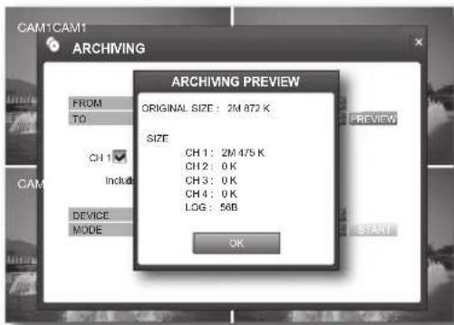
- Use the direction buttons ENTER) to select
and ,and click . - When done, goes back to the Archiving window.
settings
You can check or change the system related settings.
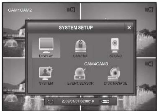
SYSTEM SETUP
You can configure the settings of DISPLAY, CAMERA, SOUND, SYSTEM, EVENT/SENSOR and DISK MANAGE.
Display
You can configure the settings of OSD and the monitor.
Using the mouse may help easier selection of related items.

-
You must press the [RETURN] button for the item selected using the < > buttons before you can move to a different menu item.
-
In Live screen, right-click any area or press the [MENU] button on the front panel or the remote control.
- Use the up/down buttons (▲▼/ENTER) to select
.
You will see the "LOGIN" dialog.
OSD
- In the
window, use the direction buttons (▲▼▲▶/ENTER) to select .
- In the
setup window, use the up/down buttons (▲▼/ENTER) to set a desired item.
status Bar:Turns on or off the status bar on the bottom of the live screen.
- camera titLe : Turns on or off the display of a cameraname on the top left corner in the monitoring mode.
- event icon : Displays the recording status icon on the top right corner
- Border: Turns on or off the display of the border in a split mode.
- motion sensor dispLay : You can set the display of the motion detection area to one of OFF/ACTIVE/INACTIVE.
- motion coLor : Set the color of the motion among blue, green, red and yellow for detection area.
Language : The player supports English, French and Spanish.
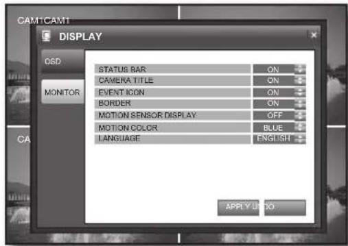

If you change the language setting, your changes will be applied after the system restarts.
- Make your settings and click
on the bottom. Your settings will be applied.
monitor
- In the
window, use the direction buttons (▲▼▲▶/ENTER) to select . -
Select
and use the up/down buttons (▲▼/ENTER) to select and set a desired item. -
seQuence dweLL : You can set the mode switch interval for sequence dwell time.
1.2.3.5.10.15.20.30.40.60 SEC
- deinterace mode : It provides correcting option of the screen trembling during playing in D1 size.
- aLarm pop-up mode: You can turn on or off the display of the alarm channel if an alarm occurs.
- aLarm pop-up dweLL : You can set the duration of the alarm dwell time if an alarm occurs.
1.2.3.5.10,15,20,30,40,60SEC
- motion pop-up mode: You can turn on or off the switching to the motion detecting channel's full screen mode if a motion is detected.
- motion pop-up dweLL : You can set the dwell time of the motion pop-up. This will display the motion popup for as much time as you specified and return to the split screen.
3.5.10.15.20.30.40.60 SEC
If an alarm occurs or a motion is detected in more than one channel, the screen will switch to a split mode for the display.
-
Make your settings and click
on the bottom. Your settings will be applied. -
When done, if you want to move to the previous menu, press the [return] button on the front panel or the remote control, or click <×> on the top right corner.
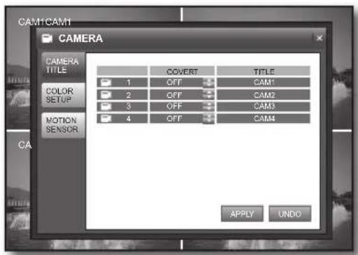
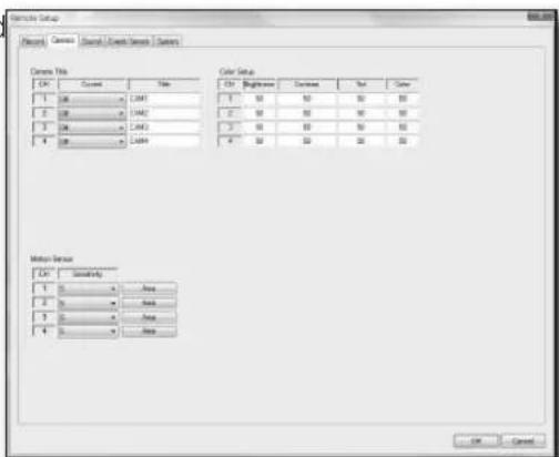
Camera
You can configure the settings of CAMERA TITLE, COLOR SETUP and MOTION SENSOR, which will display on the DVR screen.
Using the mouse may help easier selection of related items.

-
You must press the [RETURN] button for the item selected using the < > buttons before you can move to a different menu item.
-
In Live screen, right-click any area or press the [MENU] button on the front panel or the remote control.
- Use the up/down buttons (▲▼/ENTER) to select
. You will see the "LOGIN" dialog.
CAMERA TITLE
- In the
window, use the direction buttons (▲▼▲▶/ENTER) to select . - Select
and use the direction buttons (▲▼▲▶/ENTER) to select and set a desired item.
COVERT
- If set to <ON> , no information of the corresponding channel will be displayed. However, it continues recording.
-
If set to <OFF> , video input from the corresponding camera will be displayed.
-
TITLE: Enter the name of the selected camera.
- You can type in up to 11 bytes including spaces.
-
When your settings are completed, click
on the bottom. Your settings will be applied. -
When done, if you want to move to the previous menu, press the [RETURN] button on the front panel or the remote control, or click <×> on the top right corner.
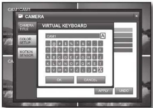
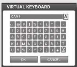
Using the Virtual Keyboard
Using the mouse may help easier selection of related items.
① Use the direction buttons (▲▼▲▶) to move to a desired character and press the [ENTER] button.
② Use the < button to erase the previous character.
③ Use the < button to toggle the letter case.
④ Complete your input and when done, click OK to close the virtual keyboard.
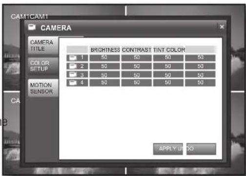
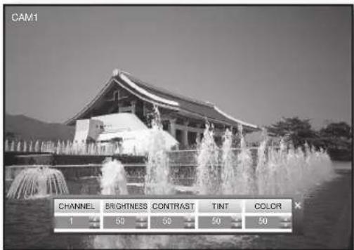
coLor setup
- In the
window, use the direction buttons (▲▼▲▶/ENTER) to select . - Select
and use the direction buttons (▲▼▶/ENTER) to select a desired item. -
If you select an item of which you want to change the setting, you will see coLor setup screen.
-
You can adjust all settings from 0 to 100 for each channel in fine tune mode, and the default is 50.
- channel: Select a channel of which you want to set the color.
- Brightness: Adjusts the brightness of the monitor.
- contrast : Adjusts the contrast of the monitor.
- tint : Adjusts the luminance of the monitor.
-
coLor : Adjusts the display color of the monitor.
-
When your settings are completed, click
on the bottom. Your settings will be applied.
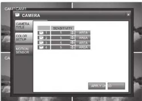
motion sensor
This menu is enabled only if you have set the motion recording in "record setup".
- In the
window, use the left/right buttons (▲▶) to select . -
Select
and use the direction buttons (▲▼▲/ ENTER) to set a desired item. -
sensitivity: Set the sensitivity of motion detection. You can adjust the sensitivity level from 1 to 10.
- area : Select an area of motion to detect.
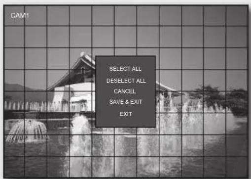
MOTION SENSOR AREA
Select on the right pane of the MOTION SENSOR window to display the MOTION SENSOR area setup screen. The borders of the selected MOTION SENSOR area cells will be shadowed.
Selecting an area with the mouse
Click a desired cell or click a point and drag it to extend as much as you want.
- The selected area will be marked yellow.
Selecting an area on the front panel or the remote control
Click a cell and press the [ENTER] button, and use the direction buttons ( ) to move to a desired cell and press the [ENTER] button to select the area.
- The selected area will be marked yellow.
Area setup using the menu
Right-click, or press the [RETURN] button on the front panel or the remote control to display the menu.
- SELECT ALL : Selects all areas.
- DESELECT ALL: Deselects all areas.
- CANCEL: Cancel your settings.
SAVE & EXIT : Saves your settings and exits the menu. - EXIT: Exits the area setup menu.
- When your settings are completed, click
on the bottom. Your settings will be applied. - When done, if you want to move to the previous menu, press the [RETURN] button on the front panel or the remote control, or click <×> on the top right corner.
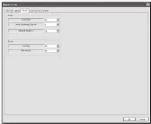
Sound
You can configure the settings of AUDIO and BUZZER.
Using the mouse may help easier selection of related items.

-
You must press the [RETURN] button for the item selected using the < > buttons before you can move to a different menu item.
-
In Live screen, right-click any area or press the [MENU] button on the front panel or the remote control.
- Use the up/down buttons (▲▼/ENTER) to select
. You will see the "LOGIN" dialog.
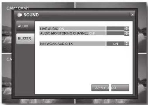
audio
- In the
window, use the direction buttons (▲▼▶/ENTER) to select . - Select
Live audio : Set the audio output.
However, the channel that is set to COVERT does not output sound. (page 26)
- audio monitoring channel: Select an audio channel to monitor among voice signals incoming from audio ports 1 through 4.
networkK audio tx : Turns on or off the function of the network audio output.
- When your settings are completed, click
on the bottom. Your settings will be applied.
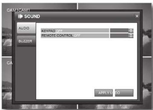
Buzzer
- In the
window, use the direction buttons (▲▼▶/ENTER) to select . -
Select
and use the up/down buttons (▲▼/ENTER) to select and set a desired item. -
Keypad : Turns on or off the buzzer in manipulation of the front buttons.
remote control:Turns on or off the buzzer in use of the remote control -
When your settings are completed, click
on the bottom. Your settings will be applied.
- When done, if you want to move to the previous menu, press the [return] button on the front panel or the remote control, or click <> on the top right corner.
System
You can configure the settings of DATE/TIME, NETWORK, MAIL, USER MANAGEMENT, SYSTEM MANAGEMENT and CONTROL DEVICE.
Using the mouse may help easier selection of related items.

-
You must press the [RETURN] button for the item selected using the < > buttons before you can move to a different menu item.
-
In Live screen, right-click any area or press the [MENU] button on the front panel or the remote control.
- Use the up/down buttons (▲▼/ENTER) to select
. You will see the "LOGIN" dialog.
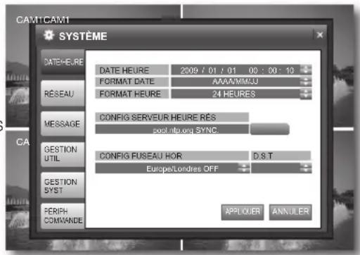
DATE/TIME
You can configure the settings of the display time, time sync and time zone.
- In the
window, use the direction buttons (▲▼▲▶/ENTER) to select - Select
and use the direction buttons (▲▼▲▶/ENTER) to select and set a desired item.
DATE TIME : Set the current time and date.
DATE FOBMAT : Set the date format
- TIME FORMAT : Set the time format to either AM/PM 12 hours or 24 hours.
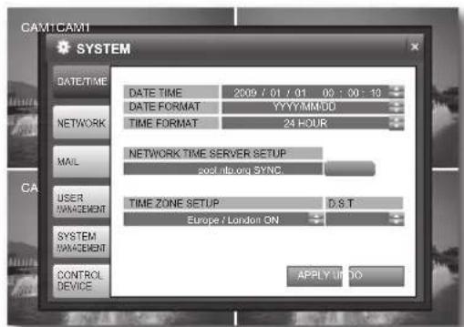
- NETWORK TIME SERVER SETUP : Set the current time using the time server. If you press the
button while connected to Internet, the time will be set from the time server. If the player has an existing recording data in the same time schedule, you are prompted to delete it.
Please check the followings if NTP does not work properly. IP ADDRESS of NETWORK / GATEWAY ADDRESS of NETWORK / SUBNET MASK of NETWORK / 1ST DNS SERVER of NETWORK / 2ND DNS SERVER of NETWORK -
TIME ZONE SETUP : Set the GMT standard time of your area.
D.S.T:Turn on or off the daylight saving time. -
When your settings are completed, click
on the bottom. Your settings will be applied.

If you want to change the time and date, you must have set DST to OFF.
Time setting in sync with the network time server
① Select a time zone for your area.
② Click
③ Set the network time server and press the
4 You can set the time manually if the time server could not set the correct time for your area.
If you does not follow the instructions above, it may find time related errors with recording and data search.

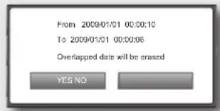
If you set the date/time to the past, you will see a warning message that prompts you to delete data if there is any in the past time you set.
- YES: Deletes the data and applies the time change.
- NO: Cancels the change of the date/time.
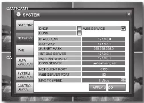
NETWORK
- In the
window, use the direction buttons (▲▼▲▶/ENTER) to select . -
Select
and use the direction buttons (▲▼▲▶/ENTER) to select and set a desired item. -
DHCP : Set the IP address of the DVR to a dynamic IP.
-
If
is selected, the setting values of IP ADDRESS, GATEWAY, SUBNET MASK, 1ST DNS SERVER and 2ND DNS SERVER will be automatically filled. -
If
is not selected, you should manually enter the setting values of IP ADDRESS, GATEWAY, SUBNET MASK, 1ST DNS SERVER and 2ND DNS S
For the IP address, contact the network administrator.
If you change the network setting, your changes will be applied after the system restarts.
- WEB SERVICE : Set the use of the web server.
- DDNS: Connect to the DVR using a specific domain name with no need to manually enter an IP address in the client side.
Refer to "DDNS Setting". (Page 32)
- IP ADDRESS: Enter an IP address.
GATEWAY: Enter a gateway address. - SUBNET MASK: Enter a subnet mask address.
- 1ST DNS SERVER: Enter the first DNS server address.
- 2ND DNS SERVER : Enter the second DNS server address.
- DDNS_SERVER : This is the address of the Samsung DDNS server that assigns a specific domain name to the set featuring the dynamic IP.
- NET CLIENT PORT : Indicates a port used when the remote management software program accesses the DVR.
- WEB SERVER PORT : Indicates a port used to connect to the DVR using the web browser.
-
MAX TX SPEED: Set the network transfer speed.
-
Select one from 56, 128, 256, 512 Kbps, 1, 2, 4 and 8 Mbps.
The video will be transferred below the set speed, which may differ according to the network connection status.
| Line Type Con | rection Mode DDNS Setting | Router Port Forwarding | ||
| Public IP Static | IP Not defined X X | |||
| Dynamic IP Defined X X | ||||
| Dynamic IP Defined O O | ||||
| Private IP Static | IP (Internal) Defined X O |
- When your settings are completed, click
on the bottom.
Your settings will be applied.
- DDNS Setting
| If the DVR is connected directly to the Internet modem | If the DVR is connected via the router | |
| 1 | Move to "SYSTEM" → "NETWORK". | |
| 2 | Set DHCP and DDNS Enabled. | Set DHCP Disabled and DDNS Enabled. |
| 3 | Restart the system. | When the system restarts, move to "SYSTEM"→ "NETWORK". |
| 4 | Move to "SYSTEM MANAGEMENT" → "SYSTEM INFORMATION". | |
| 5 | Check the DDNS Domain Name. | Check the IP address. If you are not sure about the IP, contact your network administrator. (Example of the private IP: 192.168.10.113) |
| 6 | Check the DDNS Domain Name. | |
| 7 | Restart the system. | |
| 8 | You should connect to the router and configure the router settings of Port Forwarding or DMZ Server. (DVR connection port port 6100 & 80) | |
| 9 | You should set the static IP of the DVR in accordance with port 6100 & 80 of the router. | |
| 10 | If you are using a remote access program, you can enter the set's Domain Name including the last 6 bytes of the MAC Address instead of the IP address. - If the MAC address is "00-11-5F-00-00-01", the domain name will be "http://f000001.websamsung.net". - The domain name of the appropriate set is included in the system information. | |
- In the
window, use the direction buttons (▲▼▲) to select . -
Select
and use the direction buttons ▲▼□/ ENTER) to select and set a desired item. -
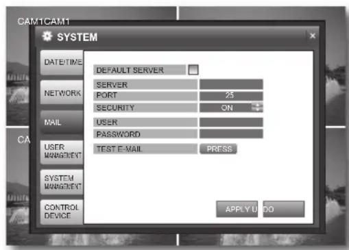
DEFAULTSERVER: If checked, you can send emails using the default email server (smtp.dvlink.net) of the DVR with no additional setting, where the sub items will be deactivated.
-
SERVER: Set the mail server.
This is a mail server used when the DVR notifies with email. -
You must use the mail server that supports Microsoft Outlook.
- Press the [ENTER] button to enter the mail server using the Virtual Keyboard. (Page 26)
You can type in up to 36 Bytes including spaces.
-
PORT: Enter the mail server port.
SECURITY -
If set to <ON> , your email will be sent in secure mode.
However, the email will not be sent if the server you entered does not support SSL. -
If set to <OFF> , this will send emails of the server that does not support SSL.
-
USER: Enter the mail account ID of the sender.
- PASSWORD: Enter the mail account password of the sender.
-
TEST E-MAIL: Sends a test email to check if the current setting can send emails normally.
-
When your settings are completed, click
on the bottom.
Your settings will be applied.
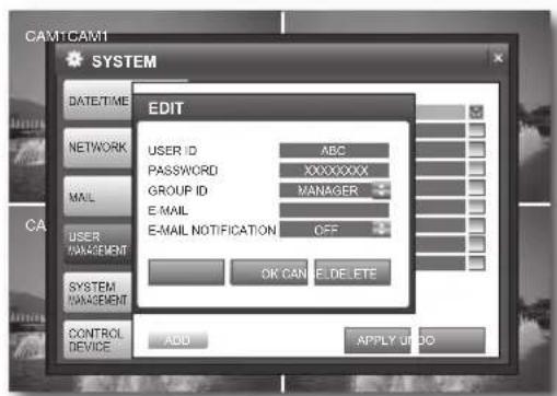
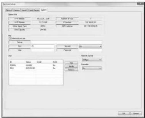
USER MANAGEMENT
- In the
window, use the direction buttons (▲▼▲▶/ENTER) to select . - Select
and use the direction buttons (▲▼▲▶/ENTER) to select and set a desired item.

The users are classified in: ADMIN, MANAGER and USER GROUP.
You can add up to 7 users including managers and users in addition to the admin; a total of 8 users can be displayed in the User List.
The ADMIN permission can manage up to 4 users
simultaneously using the remote management software and only one user can access the SYSTEM SETUP menu.
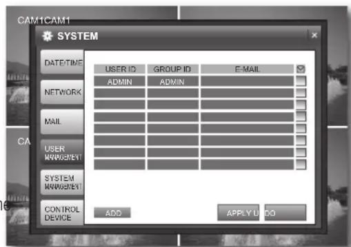
- ADMIN: Can perform all features of the DVR.
- MANAGER: Can restart or search the system.
- USER: Can play the Live screen and perform recording.
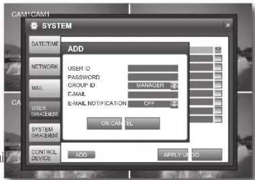
Adding a user
-
USER ID/PASSWORD: Enter the user ID and password.
-
You can type in up to 14 bytes including spaces for the password.
GROUP ID: Select one from MANAGER and USER GROUP.
E-MAIL: Enter the email address.
- Enter the whole name including the email ID and domain name.
You can type in up to 36 bytes including spaces for the email address. Refer to "Using Virtual Keyboard". (Page 26)
-
E-MAIL NOTIFICATION: Turns on or off the notifi cation of an email.
-
This is available only if you have set the E-MAIL NOTIFICATION in
.
Editing the user
To change the user information, select an applicable item. You will see the
- When your settings are completed, click
on the bottom.
Your settings will be applied.
SYSTEM MANAGEMENT
You can check the current system version and upgrade it if you want to, back up data or reset the settings.
-
In the
window, use the direction buttons (▲▼▲▶/ENTER) to select . -
Select
and use the direction buttons (▲▼▲▶/ENTER) to select and set a desired item.
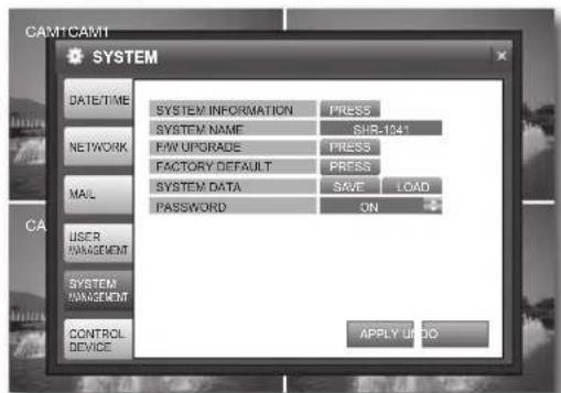
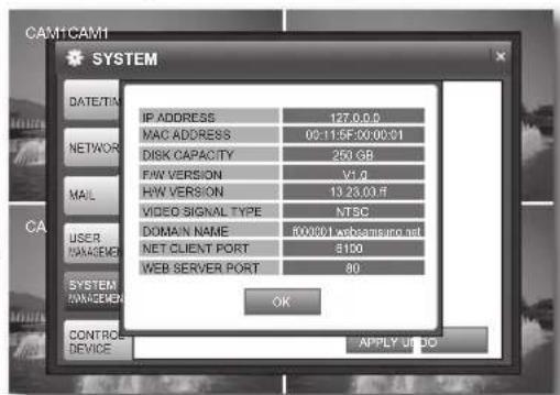
SYSTEM INFORMATION
You can check the current system version and system-related settings.
- IP ADDRESS : Displays the IP address of the DVR.
- MAC ADDRESS : Displays the DVR's MAC address.
- DISK CAPACITY : Displays the capacity of the HDD.
- F/W VERSION : Displays the firmware version.
- H/W VERSION : Displays the hardware version.
VIDEO SIGNAL TYPE : Displays the signal type of the current video. - DOMAIN NAME : Displays the domain name of the appropriate set.
-
net cLient port : Indicates the number of a port used when the remote management software program accesses the DVR.(Page 31)
-
weB server port : Indicates the number of a port used to connect to the DVR using the web browser. (Page 31)
-
system name : Set the system name. You can type in up to 15 bytes.
-
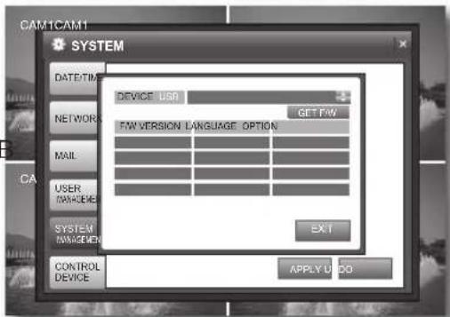
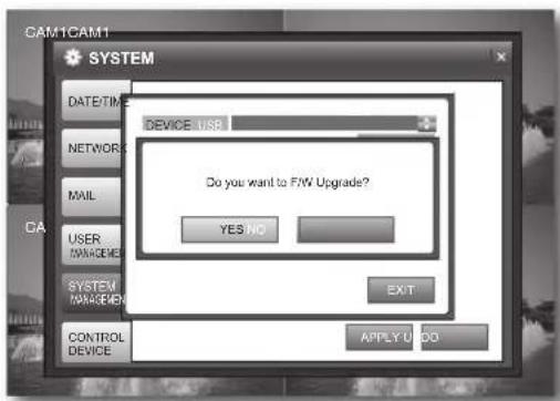
F/w upgrade : You can upgrade the current software version.
-
Please, disconnect LAN cable in upgrading the F/W. - If you select
, the "Login" dialog appears.
① Connect the device storing the update files to the USB port.
② Select press in F/W UPGRADE. When you see the "Login" dialog, enter the password.
③ When you select <get F/w> , you will see the fi rmware list.
Use the direction buttons /ENTER) to select the latest firmware version and press [enter].
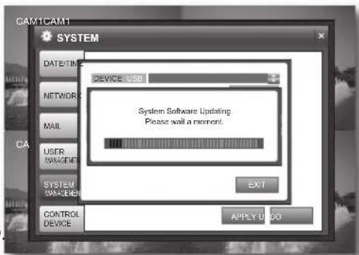
⑤ Select < yes> in the FAW upgrade window.
The update status bar appears and the system will perform the upgrade.
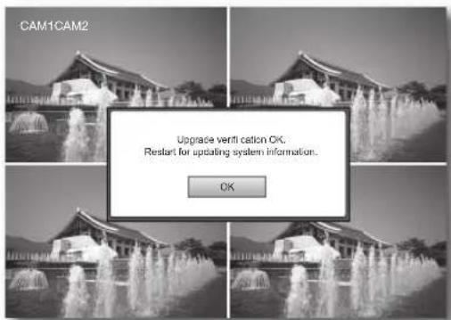
When the upgrade is completed, you are prompted to select <oK> in the system reboot dialog. The upgrade is completed and the system restarts.
If you select <oK> in the upgrade confirmation dialog, the system will restart.
Factory deFauLt:Restore the DVR settings to the factory default.
It is recommended to back up the system data before performing the F/W upgrade.
-
If you select
, the "Login" dialog appears. If you select in the confirmation dialog, the system will be reset to the default. -
If the system is reset, the existing data will not be deleted.
-
In the factory default, you can select to format the HDD
SYSTEM DATA
: Applies the setting information in the storage device to the DVR.
① Connect the device to store the system data to the USB port.
② Select < SAVE> to store the system data.-
: Stores the setting information of the DVR into the storage device.
① Connect the storage device to the USB port of the system.
② Select
③ Enter the password in the "LOGIN" dialog.
④ In the "SYSTEM DATA LOAD" confirmation window, select OK. -
PASSWORD : Turns on or off the popup of the "LOGIN" dialog if you access a menu item such as Search, Archiving, Search Setup and Shutdown in the menu.

If you load the system data, your changes will be applied after the system restarts.
- When your settings are completed, click
on the bottom. Your settings will be applied.
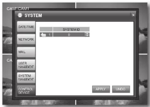
CONTROL DEVICE
- In the
window, use the direction buttons (▲▼▲▶/ENTER) to select . -
Select
and use the up/down buttons (▲▼/ENTER) to select and set a desired item. -
SYSTEM ID : Use the remote control to select a control number from 0 to 99. The default ID is 0.
Refer to "Changing the Remote Control ID". (Page 10)
- When your settings are completed, click
on the bottom.
Your settings will be applied.
- When done, if you want to move to the previous menu, press the [RETURN] button on the front panel or the remote control, or click <X> on the top right corner.
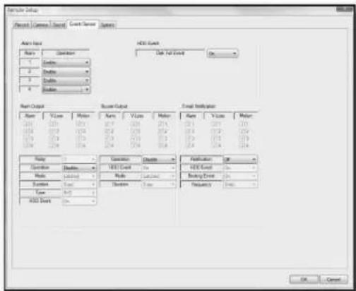
Event/Sensor
You can configure the settings of HDD EVENT, ALARM INPUT, ALARM OUTPUT, BUZZER OUTPUT and E-MAIL NOTIFICATION.
Using the mouse may help easier selection of related items.

-
You must press the [RETURN] button for the item selected using the < > buttons before you can move to a different menu item.
-
In Live screen, right-click any area or press the [MENU] button on the front panel or the remote control.
- Use the up/down buttons (▲▼/ENTER) to select
. You will see the "LOGIN" dialog.
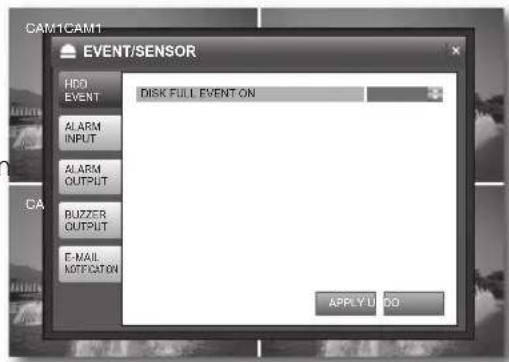
HDD EVENT
- In the
window, use the direction buttons (▲▼▲▶/ENTER) to select . -
Select
and use the up/down buttons (▲▼/ENTER) to set a desired item. -
DISK FULL EVENT: You can set to notify the user when the HDD is full.
-
This is applied only if you have set
in to . -
When your settings are completed, click
on the bottom.
Your settings will be applied.
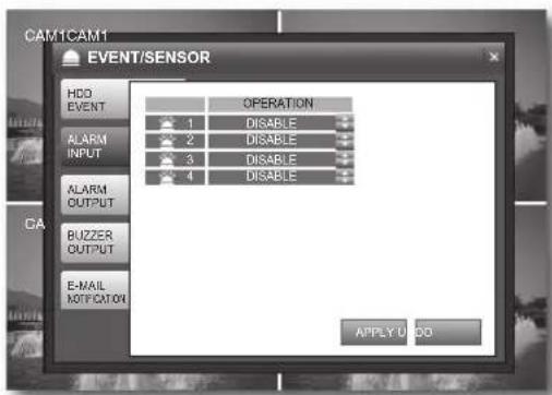
ALARM INPUT
- In the
window, use the direction buttons (▲▼▲▶/ENTER) to select . -
Select
and use the direction buttons (▲▼▲▶/ENTER) to set a desired item. -
OPERATION : Set the connection status of the alarm sensor to either ENABLE or DISABLE.
- If the alarm sensor is set to
and you have set to perform recording if an alarm occurs, the Live screen displays the alarm recording standby mode. (Page 18) -
The INPUT type of the alarm is N/O(Normal Open).
-
When your settings are completed, click
on the bottom.
Your settings will be applied.
ALARM OUTPUT
- In the
window, use the direction buttons (▲▼▲▶/ENTER) to select . -
Select
and use the direction buttons (▲▼▲▶/ENTER) to select and set a desired item. -
OPERATION : Set the operation of the alarm output.
- If set to
, the applicable menu is activated where you can set other options. -
If set to <DISABLE> , other items will be disabled.
-
MODE : Set the output mode of the alarm.
-
If set to
, the alarm will sound for as much time as defined in DURATION. - If set to
, the DURATION item will be disabled.
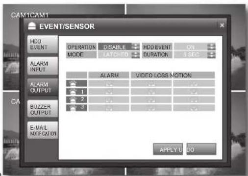
-
HDD EVENT : Set to use the alarm output if the HDD is full.
DURATION : Set the duration of the alarm output. -
If you select
, the buzzer will be stopped when you press any button on the front panel or the remote control. -
ALARM,VIDEO LOSS, MOTION : Set the alarm output for each channel if an event of alarm, video loss or motion detection occurs.
-
When your settings are completed, click
on the bottom. Your settings will be applied.
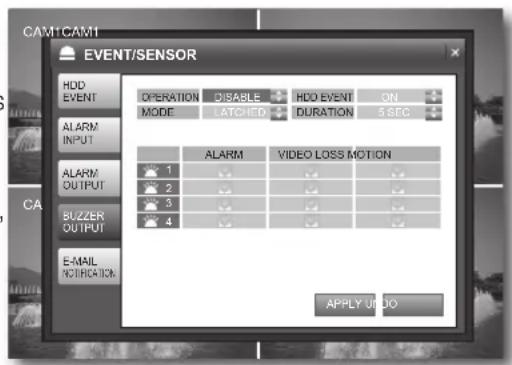
BUZZER OUTPUT
- In the
window, use the direction buttons (▲▼▲▶/ENTER) to select . -
Select
and use the direction buttons (▲▼▶/ENTER) to select and set a desired item. -
OPERATION : Set the operation of the buzzer output.
- N/O(Normal Open): Sensor is open in normal condition, it generates alarm if the sensor is closed.
- HDD EVENT: Set the buzzer output if a HDD event occurs.
-
MODE : Set the output mode of the buzzer.
-
If set to <LATCHED> , the buzzer will sound for as much time as defined in DURATION.
- If set to
, the DURATION item will be disabled.
DURATION: Set the duration of the buzzer output.
- If you select
- ALARM,VIDEO LOSS, MOTION: Set the buzzer output for each channel if an event of alarm, video loss or motion detection occurs.
- When your settings are completed, click
on the bottom. Your settings will be applied.
E-MAIL NOTIFICATION
- In the
window, use the direction buttons (▲▼▲▶/ENTER) to select . -
Select
and use the direction buttons (▲▼▲▶/ENTER) to select and set a desired item. -
NOTIFICATION: Turn on or off the notifi cation of an event if it occurs.
-
If set to <ON> , the applicable menu is activated where you can set other options.
-
If set to <OFF> , other items will be disabled.
-
HDD EVENT: Turn on or off the notification of a HDD event if it occurs.
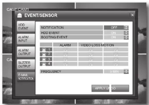
- BOOTING EVENT: Turn on or off the notification of an email when the system boots.
-
ALARM,VIDEO LOSS,MOTION:Set the event notification for each channel if an event occurs such as alarm, video loss or motion detection.
FREQUENCY : Set the notification interval for events occurred. (10MIN~30MIN, Default: 30MIN) -
When your settings are completed, click
on the bottom. Your settings will be applied. - When done, if you want to move to the previous menu, press the [RETURN] button on the front panel or the remote control, or click <×> on the top right corner.

- A photo taken in a low contrast scene naturally causes a lot of noise, and often occurs an unnecessary motion event, which may cause damage to the camera set. In such case, set a function of E-MAIL NOTIFICATION to OFF, or set FREQUENCY to a longer time (ex: 30 MIN).
- You are recommended to use a night vision camera in a low contrast scene.
You can confi gure the settings of DISK MANAGE related to the HDD.
Using the mouse may help easier selection of related items.

-
You must press the [RETURN] button for the item selected using the < > buttons before you can move to a different menu item.
-
In Live screen, right-click any area or press the [MENU] button on the front panel or the remote control.
- Use the up/down buttons (▲▼/ENTER) to select
. You will see the "LOGIN" dialog.
DISK MANAGEMENT
- In the
window, use the left/right buttons (▲▼▲▶/ENTER) to select . - Use the direction buttons (▲▼/ENTER) to select and set a desired item.
OVERWRITE
- If set to <ON> , recording will proceed by overwriting the existing data even if the size of the recording data exceeds the HDD capacity.
- If set to
and the HDD is full, the DVR stops recording and sounds the buzzer or alarm that is set to operate in . (Page 36) A message of "DISK FULL" is displayed on the screen.
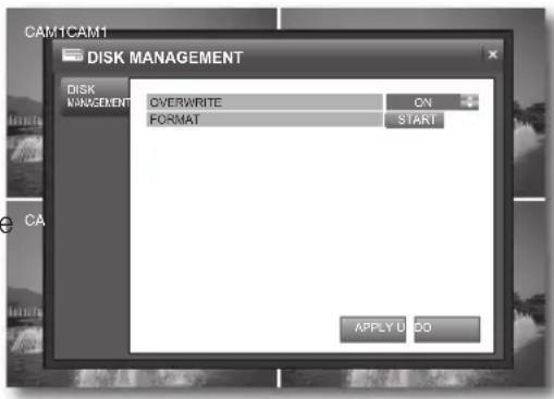
- FORMAT: Format the hard disk drive. All existing data will be lost.
① Select
② Enter the password in the "LOGIN" dialog.
③ In the "FORMAT" confirmation window, select
④ When done, select <OK> if you see a message of "You must restart this system" on the screen.

Note that formatting the HDD will delete all existing data.
- When your settings are completed, click
.
You will see the system reboot dialog.
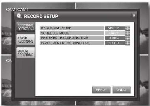
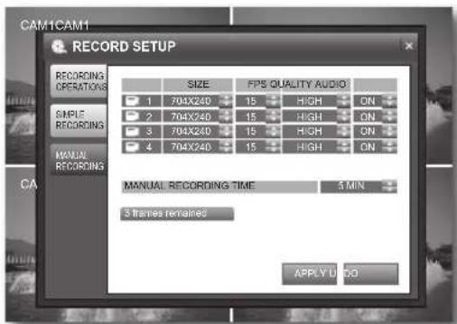
RECORD
You can configure the settings of record-related options such as RECORDING OPERATIONS, SIMPLE RECORDING, ADVANCED RECORDING and MANUAL RECORDING.
Record Setup
Using the mouse may help easier selection of related items.

-
You must press the [RETURN] button for the item selected using the < > buttons before you can move to a different menu item.
-
In Live screen, right-click any area or press the [MENU] button on the front panel or the remote control.
- Use the up/down buttons (▲▼/ENTER) to select
. You will see the "LOGIN" dialog.
-
Select
and use the up/down buttons (▲▼/ENTER) to select and set a desired item. -
RECORDING MODE: Select one from
and . -
SCHEDULE MODE
-
This is activated if you select
, where you can select a mode from and . -
If you select
, this will be fixed to and disabled. -
PRE EVENT RECORDING TIME : Recording will start before the set time if an event occurs.
- POST EVENT RECORDING TIME : Recording will proceed until over the set time if an event occurs.
- When your settings are completed, click
on the bottom. Your settings will be applied.
simpLe recording
If you set
-
Select
and use the up/down buttons (▲▼/ ENTER) to set a desired item. -
record Quality: Set the recording quality. Select one from LOW/STANDARD/HIGH/HIGHEST. The recordable time may differ, depending on the recording quality.
- record size : Set the recording resolution.
- Fps : Set the frame rate per second.
- time Bar: You can select a recording type for the time line of each channel. Use the mouse to drag and drop a time line or use the left/right buttons
() on the front panel or the remote control to select a time line and press [enter]. Select an item to record and click <0K> .
-
continuous : Performs the recording continuously.
-
motion : The recording will perform only if a motion is detected.
To record a motion, set both
- aLarm : The recording will perform only if an alarm occurs.
To record an alarm event, set
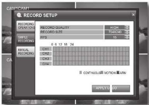

- The icon of applicable recording mode is displayed on the Live screen. (Page 18) If you select no record type, the timeline record does not perform.
The record size affects the FPS.
| record size possiBLe | Fps |
| 352 × 240 1, 2, 3, 7 | 15, 30 |
| 704 × 240 1, 2, 3, 7 | 15 |
| 704 × 480 1, 2, 3, 7 |
- When your settings are completed, click
on the bottom. Your settings will be applied.
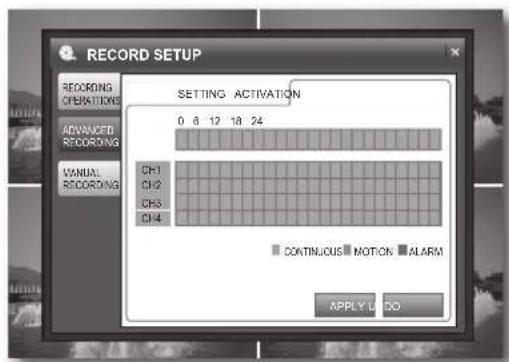
advanced recording
If you set
- Select
and use the up/down buttons (▲▼/ENTER) to set a desired item.
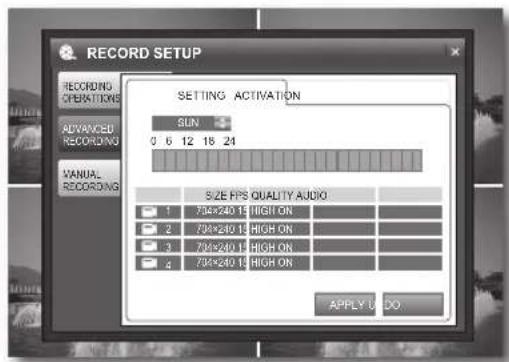
In RECORDING OPERATIONS, setting the schedule mode to
Use the mouse to drag and drop a time line or use the left/right buttons () on the front panel or the remote control to select a time line and press [enter].
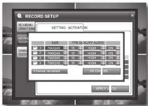
② Set size, Fps, QuaLity and audio for each channel and click
- Please check the value of < frames remained> on the bottom before you set SIZE and FPS. If the first digit displays " - ", your settings will not be saved.
size: Set the recording resolution.
-Fps:Set the recording frame rate.
- Quality : Select one from LOW/STANDARD/HIGH/ HIGHEST.
- audio : Select whether to include audio input to the recording.
- activation: Set an item to synchronize with recording on that specific time defined in
- When your settings are completed, click
on the bottom.
Your settings will be applied.
manual recording
-
Select
and use the direction buttons (▲▼▲/ENTER) to set a desired item. -
size : Set the recording resolution.
- Fps : Set the recording frame rate.
- QuaLity : Select one from LOW/STANDARD/HIGH/ HIGHEST.
- audio : Select whether to include audio input to the recording.
- manual recording time : Set the duration of the manual recording.
- When your settings are completed, click
on the bottom. Your settings will be applied. - When done, if you want to move to the previous menu, press the [return] button on the front panel or the remote control, or click <回> on the top right corner.
INTRODUCTION
What is Web Viewer?
Web Viewer a user friendly software program that enables you to connect to the DVR in a remote area and control the live or existing video data.
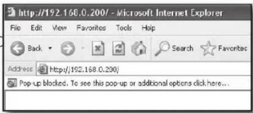
CONNECTING WEB VIEWER
- Open the web browser and enter the IP address or URL of the DVR in the address bar. The default URL of the DVR includes the last six digits of the MAC address.

- You must have set the DDNS values in "NETWORK>DDNS". (Page 31)
-
You must type in "f" as an identification code before the MAC address. Refer to the DOMAIN NAME included in the system information. (Page 34) Ex) if the MAC address is 00-00-F0-ab-cd-ef: http://fababcdef.websamsung.net
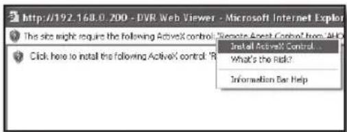
If you know the IP address, you can type it directly. -
Click
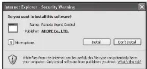
to install the ActiveX control.
- In the security alert popup, click
.
- If you see the "SETUP" window, click
.
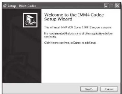
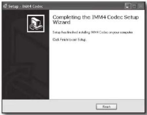
- When the setup is done, click
.
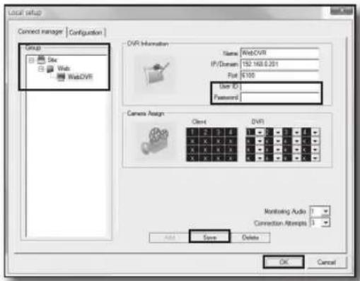
- The installation process is completed and you will see the "Local setup" window. Enter the user ID and password.
- Select
and click OK>. You will see the DVR is added in the left pane.
- Click the connection ()icon in the left corner of the Live screen. You will see the "Connection state" window.
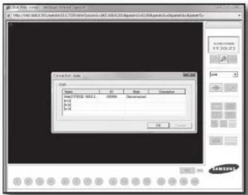
- When connected properly, you will see the DVR's Live screen.
CONNECTING DVR
In the Live screen, click the local setup icon to display the Local setup window.
Connection Manager
Enables you to control access to the DVR from remote users.
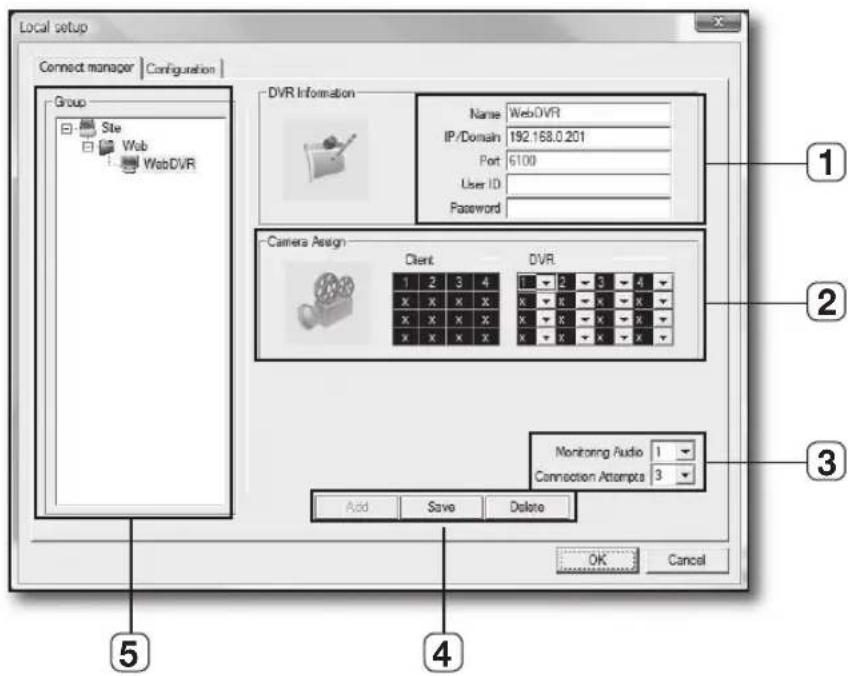
| Item Description | ||
| 1 | DVR Information You can register the connection information of each DVR. | |
| 2 | Camera Assignment Set the camera position of a registered DVR. | |
| 3 | Monitoring Audio/ Connection Attempts | - Monitoring Audio : Set the audio output channel. - Connection Attempts : Set the times of an attempt to connect to the DVR in case of a connection failure. |
| 4 | Button Bar | - Add : Adds your settings. - Save : Saves your settings. - Delete : Deletes your settings. |
| 5 | Group & DVR List | You can add a DVR group which will be displayed in the DVR list. |
You can confi gure the settings of the video output to the PC in remote connection with the DVR.
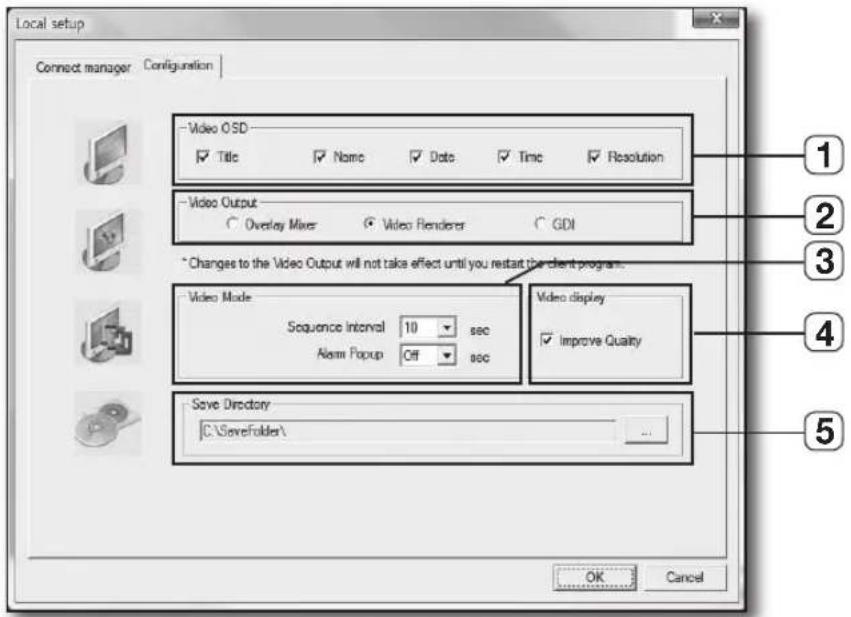
| Name Description | ||
| 1 | Video OSD Select a | item or items to display on the screen. |
| 2 | Video Output | Select a type of the video output. - Overlay Mixer: Enables faster video transfer. Select this if your graphics adaptor supports the feature of overlay mixer. - Video Renderer: Select this if your graphics adaptor does not support Overlay but the feature of Direct Draw. - GDI: Select this if your graphics adaptor supports neither of the two above. |
| 3 | Video Mode | - Sequence Interval: Set the sequence interval of the image. - Alarm Popup: Set the duration of an alarm popup that appears in sync with the related video screen if an alarm occurs in the system. |
| 4 | Video Display Set the | use of the quality improvement feature. |
| 5 | Save Directory | Set the default file path to save the backup image. |
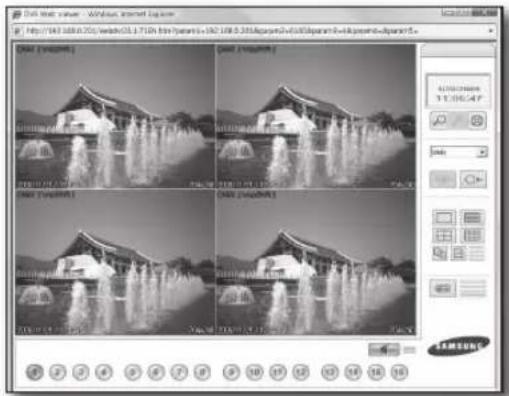
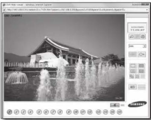
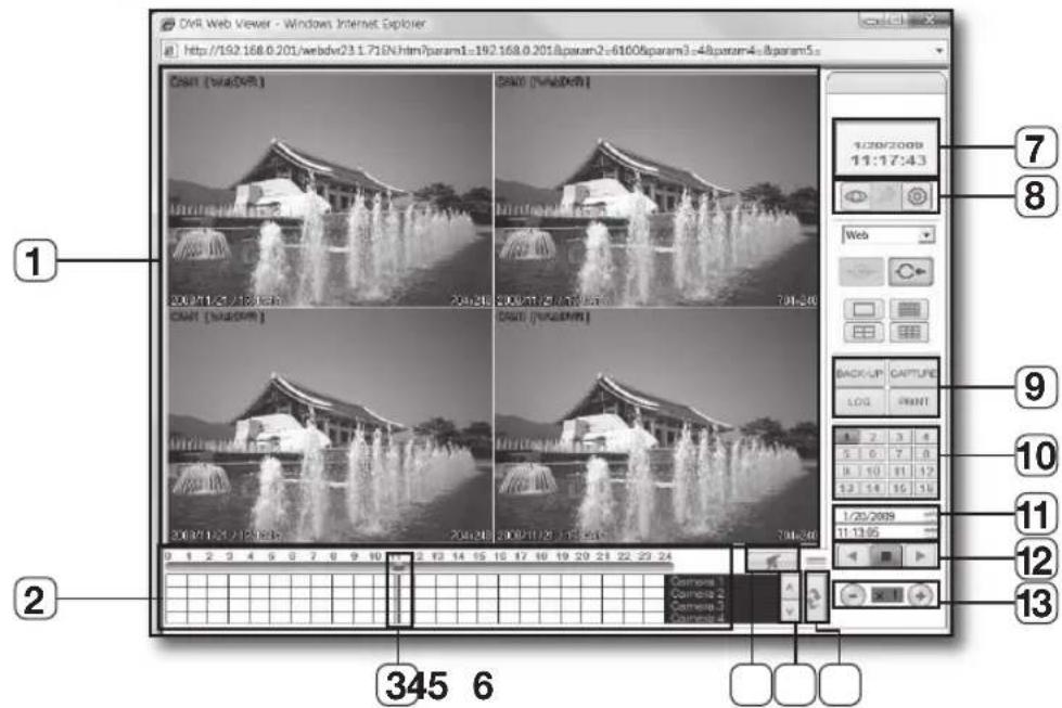
USING LIVE VIEWER
Enter the IP address of the DVR in the web browser's address bar to display the web viewer when the DVR is connected in the "Local Connection" window.
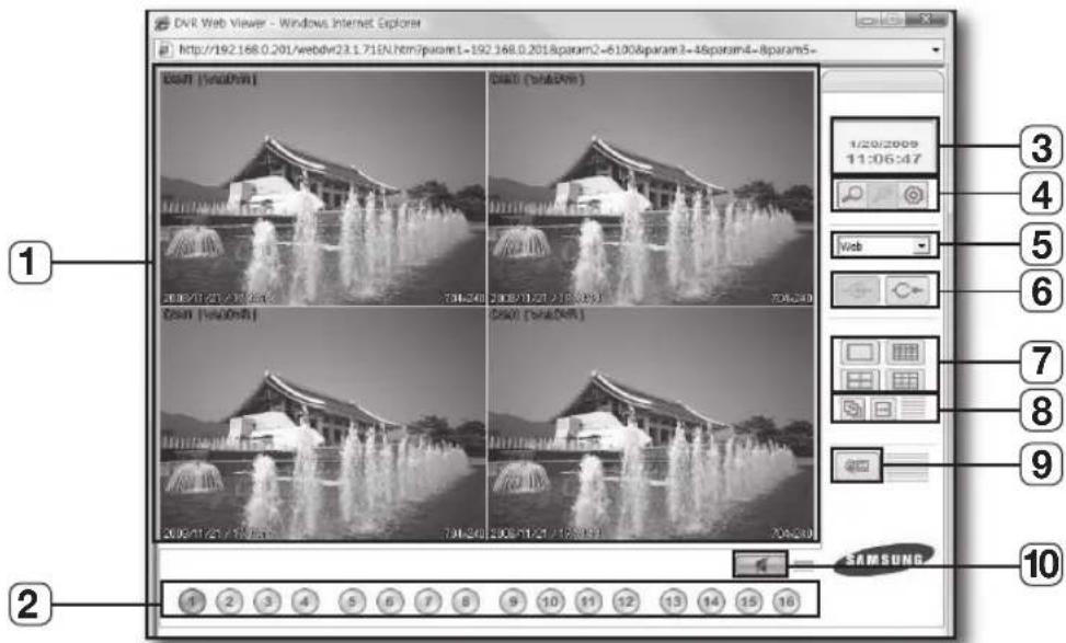
| Name Description | ||
| 1 | Main Screen Displays the Live image of the DVR that is currently connected. | |
| 2 | Camera Selection | Displays the channel number of the camera that is connected to the DVR. If you click this in Single mode, the video image of the connected camera will be displayed. |
| 3 | PC Time Displays the PC use time of the current user. | |
| 4 | Search/Local Setup/Remote Setup | - Search: Use this if you want to switch to search mode. - Local Setup: The Local Setup button is enabled only if a DVR isn't connected. - Remote Setup: Use this if you want to confi gure the DVR settings. The Search and Remote Setup buttons are enabled only if a DVR is connected. |
| 5 | DVR Selection Box Select a DVR group to connect to. | |
| 6 | Connect/Disconnect | - Connect: Use this to connect to a DVR. ■ Connection is made by the DVR group. - Disconnect: Use this to disconnect from the current DVR. |
| 7 | Split Screen Switch the split mode. (1/4/9/16-split) | |
| 8 | Auto Sequence, Manual Sequence | - Auto Sequence : Automatically sequences the camera video images. - Manual Sequence : Manually sequences the camera video images. |
| 9 | Save AVI Saves the current Live video in the format of AVI. | |
| 10 | Mute | If you click this, you can hear the voice sound alone from the speaker in the web viewer and click it again to disable the speaker. |
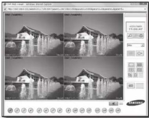
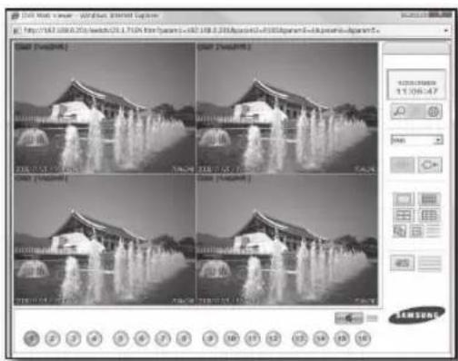
Live Screen in Split Mode
You can play a live or recorded video of the DVR in a split or Single mode.
- The video will be played live in Single mode when you first connect to the DVR.
- Use the number buttons on the bottom to click a desired channel. The selected channel will be played live in Single mode.
Switching to Split Mode
- Click the split mode icon in the right menu of the Live screen.
- You will see the live video in a split mode.
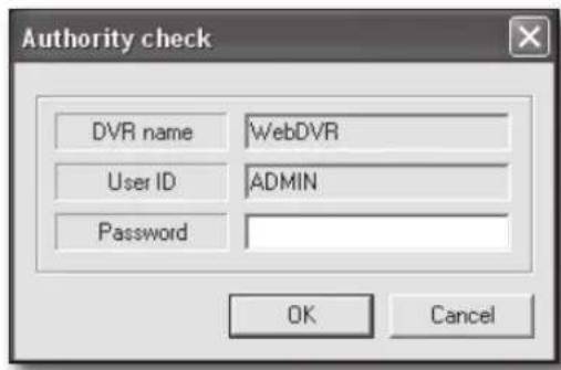
REMOTE SETUP
Click the remote setup < 0> icon in the Live screen.
You will see the "Authority Check" dialog.
Enter the password to display the "Remote Setup" window.
Refer to step 5 in "Using Live Viewer". (Page 48)
- When more than two DVRs registered, you will see DVR selecting screen first.
Record
You can set the record quality and scheduling.
For more information, refer to "Record Setup". (Page 40)
- Simple Record
If you select the record mode to
Set the record quality, size and frame rate.
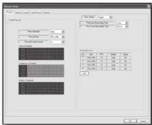
- Advance
If you select the record mode to
Select a schedule mode from

Camera
You can set the display, color and motion area for the selected camera.
For more information, refer to "Camera". (Page 25)
Sound
You can confi gure the audio and buzzer related settings.
For more information, refer to "Sound". (Page 28)
Audio
Set the use of audio output.
- Buzzer
Set the buzzer output in use of the keypad and remote control connected to the DVR.
Event/Sensor
You can set the alarm event and the use, channel and interval of the alarm if it occurs.
For more information, refer to "Event/Sensor". (Page 36)
System
You can check the system information of the DVR and set the use of SMTP server authentication, and add or edit a user.
For more information, refer to "System". (Page 30)
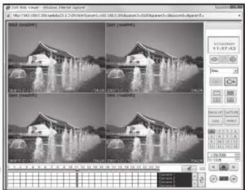
SEARCH
You can search for and play a DVR video according to a desired time or the log information.
Using Search Viewer
| Name Description | ||
| 1 | Monitoring Screen Displays video channels found. | |
| 2 | Time Clock Displays the time line of a recorded video. | |
| 3 | Time Clock Cursor Use this to select a desired time line. | |
| 4 | Mute Button | Controls the audio output of a video channel. (Speaker On/Off) |
| 5 | Time Clock Channel Search Bar | Use this if you want to move to a channel for visual check. |
| 6 | Reset Time Clock Reloads the recording status of the DVR. | |
| 7 | Date, Time Displays the time of the PC. | |
| 8 | Live, Local Setup, Remote Setup | Live button: Use this if you want to switch to Live mode. |
| 9 | Backup, Screen Capture, Log Viewer, Video Printout | - Backup: Displays a video backup window. - Screen Capture: Displays a dialog that prompts you to select a file path to save the current screen. - Log Viewer: Displays the log viewer. - Video Printout: Prints out the current screen. |
| 10 | Camera Channel Select a camera. | |
| 11 | Time Control | Displays the time of the video. You can also use this to enter a search time for a desired video. |
| 12 | Play Backward, Stop, Play Forward | You can select a playback option from Play Backward, Stop and Play Forward. |
| 13 | Play Speed You can adjust the play speed of the video. | |
- Click the search icon in the search bar of the Live screen.
The icon will turn into the Live icon and the screen will switch to the search mode.
- When more than two DVRs registered, you will see DVR selecting screen first.
- Move the time clock cursor to a desired point or use the time control to enter a desired time.
If you change the time point by using any of the time clock cursor or the time control, the changed time will be synchronized accordingly.
The blue highlighted area indicates a recorded time interval by the DVR.
-
Click the forward or backward play button.
-
You can adjust the speed during the playback by using the speed button.
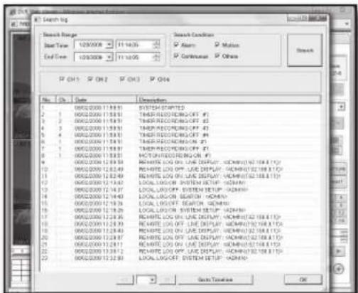
Search by Log
- Click the log <icon in search mode.
- Set a desired time line in
. - Click a desired event type in
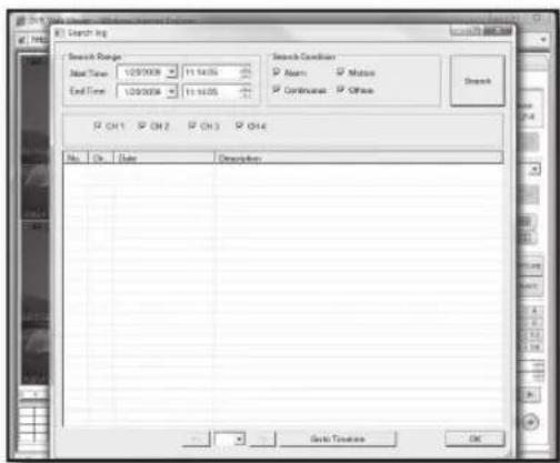
web viewer
- Click
.
You will see a list of log events found.
- Find an event, and double-click on it or simply click
.
The time cursor will move to the event occurrence time; you can search for a desired video the same way you use the time clock.

If you use play options of Playback and Backup in the DVR, you are disabled to perform the playback or backup in the web viewer.
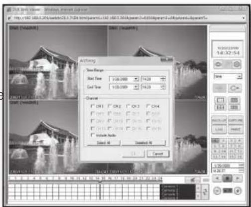
Backup Recording Data
- Click the backup<icon
- Set the backup start and end times in the "Archiving" window.

If the start time is later than the end time, you will see a message of "Invalid backup setting" on the screen.
- Select a video channel to backup.
Select a checkbox of "Include Audio" if you want to include audio for the backup.
- Click
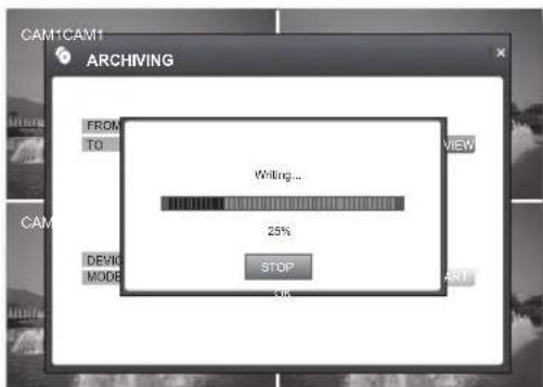
to start the backup.
During the backup, the backup progression window appears to display the backup status.
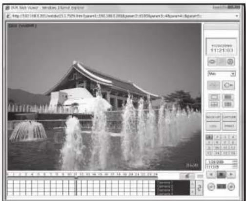
Checking Audio Recording Data
- To check for any voice recording data, click the search icon.
- Use the cursor of the time clock to play video in a desired time line.
- To switch the current screen to Single mode, click the Single mode icon.
- Use the number buttons on the bottom to select a desired channel.
- To play a video channel including audio recording, make sure to play the video channel in Single mode only.
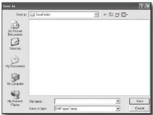
Saves the current screen as an image file.
-
While the DVR is playing a video, click the capture icon. The Save As dialog appears.
-
Save the captured still image as a desired name.
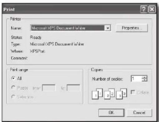
Video Printout
You can print out the current screen or a specific image of the DVR.
- When the DVR is playing or stops playing a DVR video, simply click the < button >icon.
- You will see the "Print" window.

Set the printer as the one connected to the PC.
- Click
to start printing out.
PRODUCT SPECIFICATION
| Item Details | ||
| Operating System Linux | ||
| Video | Video System NTSC | |
| Video Input | BNC Type:4 EA | |
| DIY Camera(RJ-11):4EA | ||
| Video Output | Composite 1 Channel(CVBS) | |
| VGA:1 EA | ||
| Display Mode Single/Quad, Sequence | ||
| Sequence Select between 1 sec to 60 sec | ||
| Event List Sensor, Motion, Video Loss,HDD Failure | ||
| Function Sequence Display Mode | ||
| Audio | Audio Input MIC equipped CAMERA(RJ-11):4CH | |
| Audio Output RCA:1CH | ||
| Alarm/Motion | Input Alarm equipped CAMERA:4CH | |
| Output Relay:1CH, Normally Open or Normally Closed Programmable | ||
| Pre Record Select between 0 sec to 5 sec | ||
| Post Record Select between 5 sec to 180 sec | ||
| Duration 5sec~60sec,2min~5min | ||
| Buzzer Yes | ||
| Motion Detection | 4CH | |
| Level:1,2,...,9,10 | ||
| Rec/Play/Search | Video Pop-up Select between 1 sec to 60 sec | |
| Video Codec MPEG4 | ||
| Audio Codec | G.711(64kbps) | |
| Video REC | 120 ips (CIF),60ips(Half D1),30ips(D1) | |
| CIF(352X240),Half D1(704X240),D1(704X480) | ||
| Rec.Quality | Level: Highest/ High/ Standard/ Low | |
| Performance | Triplex (Playback, Recording, Network) | |
| # of Video Record | 4CH | |
| REC Mode | Manual, Motion, Alarm, Schedule | |
| Snap shot | 1 Snap Image Recording | |
| Play Speed | FW,REW,X64,X32,X16,X8,X4,X2,X1 Play,Pause | |
| Storage | 250GB Base (SATA),Max 500GB | |
| Search Mode | Time,Event | |
| Network | Remote Viewer | AV Stream Transmit Protocol -TCP/IP |
| DDNS Server Use, Dynamic IP Connection | ||
| Single/Quad, Sequence | ||
| Maximum # of Connection: 4 User | ||
| Record in remote PC | ||
| Network 10/100Base-T Support | ||
| Network Protocol TCP/IP, DHCP, DDNS | ||
| PC Environment Windows XP, Windows VISTA | ||
| Remote Monitoring Speed Bandwidth Management | ||
| Remote Searching Date/Time, Event List Search | ||
| Security Password / User Name Protection , Watermark | ||
| Web Browser Version MS Explorer 5.5 up | ||
| Backup Backup USB2.0 | ||
| Time Time Adjutment | GMT Time Zone, Auto DST, NTP | Support |
| Interface Mouse PS/2 | ||
| Power | Power DC 12V/4A (Adaptor) | |
| Power consumption 20W | ||
| Operation Temp | 0 °C ~ 40 °C (32°F ~ 104°F) | |
| Storage Temp | -20 °C ~ 60 °C (-4°F ~ 140°F) | |
| Operating Humidity | 20% ~ 85% RH | |
| Storage Humidity | 20% ~ 95% RH | |
| Dimensions | Set (WxDxH) | 290 x 307 x 58 (mm) |
| Package (WxDxH) | 448 x 398 x 192 (mm) | |
| Weight | Set | 2.55(Kg), 5.62(Lbs) |
| Package | 8.7(Kg), 19.18(Lbs) | |
SAMSUNG
DVR à 4 canaux
Guide d'utiliation
imaginez les positibilities
Bloc-piles
1,2,3,5,10,15,20,30,40,60S
AAAA/MM/JJ,JJ/MM/AAAA,MM/JJ/AAAA
CÁMARA DE VISION NOCTURNA


- Channel DVR User Manual
- Features
- BEFORE START
- Warning
- Battery
- CALIFORNIA USA ONLY
- System Shutdown
- Operating Temperature
- Package Contents
- contents
- overview
- installation
- getting started
- Live
- search
- settings
- weB viewer
- appendix
- PART NAMES AND FUNCTIONS (FRONT)
- REMOTE CONTROLLER
- Changing the remote control ID
- Camera Part Names
- Pin Setting
- Installing the Camera
- NIGHT-VISION CAMERA
- Installing the Night-Vision Camera
- Camera Bracket Specification
- Adjusting the Camera Bracket
- CONNECTING WITH OTHER DEVICE
- Connecting Alarm Output and Relay
- Connecting the Network
- starting the system
- Login
- Sequence
- Logoff
- KEY LOCK
- Search by Time
- - Using the play button bar
- Search by Event
- backup
- ARCHIVING
- SYSTEM SETUP
- Display
- OSD
- monitor
- Camera
- CAMERA TITLE
- COVERT
- Using the Virtual Keyboard
- coLor setup
- motion sensor
- MOTION SENSOR AREA
- Selecting an area with the mouse
- Selecting an area on the front panel or the remote control
- Area setup using the menu
- Sound
- audio
- Buzzer
- System
- DATE/TIME
- Time setting in sync with the network time server
- NETWORK
- USER MANAGEMENT
- Adding a user
- Editing the user
- SYSTEM MANAGEMENT
- SYSTEM INFORMATION
- SYSTEM DATA
- CONTROL DEVICE
- Event/Sensor
- HDD EVENT
- ALARM INPUT
- ALARM OUTPUT
- BUZZER OUTPUT
- E-MAIL NOTIFICATION
- DISK MANAGEMENT
- OVERWRITE
- RECORD
- Record Setup
- simpLe recording
- advanced recording
- manual recording
- INTRODUCTION
- What is Web Viewer?
- CONNECTING WEB VIEWER
- CONNECTING DVR
- Connection Manager
- USING LIVE VIEWER
- Live Screen in Split Mode
- Switching to Split Mode
- REMOTE SETUP
- Using Search Viewer
- Search by Log
- Backup Recording Data
- Checking Audio Recording Data
- Video Printout
- DVR à 4 canaux
- Guide d'utiliation
- imaginez les positibilities
- Bloc-piles
- CÁMARA DE VISION NOCTURNA
Brand : SAMSUNG
Model : SHR1041K
Category : Surveillance Camera