
AHX10BE - Air conditioner SHARP - Free user manual and instructions
Find the device manual for free AHX10BE SHARP in PDF.
| Product type | Split air conditioner (indoor and outdoor units) |
| Brand | Sharp |
| Model | AHX10BE |
| Power supply | 230 V / 50 Hz (estimated) |
| Operating modes | Auto, Cool, Dry, Fan only |
| Service temperature range (Cool) | Indoor: 21 °C to 32 °C; Outdoor: 21 °C to 43 °C |
| Remote control | Yes, with LCD display and 7-meter range |
| Timer | On/Off timer (10 min steps), 1-hour off timer |
| Powerful mode | Yes, maximum power operation |
| Airflow direction | Vertical (motorized) and horizontal (manual) |
| Air filters | Washable, cleaning recommended every 2 weeks |
| Optional air purifying filter | Yes, disposable type (lifespan 3 to 6 months) |
| Auxiliary mode (without remote control) | Yes, AUX button on indoor unit |
| Memory function | Stores settings in case of power failure |
| Auto sleep function | Yes, in Cool mode: +1°C after 1h; in Dry mode: similar |
| Indicator lights | OPERATION (red), TIMER (orange), TEMPERATURE (green), POWER MONITOR |
| Cleaning and maintenance | Wipe with a soft cloth; do not use water, solvents or abrasive powders |
| Safety | Mandatory grounding; automatic stop in case of anomaly; use by children or disabled persons under supervision |
| Spare parts and repairability | Installation, removal and repair by qualified technician only; parts available from dealer |
Frequently Asked Questions - AHX10BE SHARP
User questions about AHX10BE SHARP
0 question about this device. Answer the ones you know or ask your own.
Ask a new question about this device
Download the instructions for your Air conditioner in PDF format for free! Find your manual AHX10BE - SHARP and take your electronic device back in hand. On this page are published all the documents necessary for the use of your device. AHX10BE by SHARP.
USER MANUAL AHX10BE SHARP
natural_image
Illustration of a wall-mounted air conditioner with a handheld remote control emitting a light beam (no text or symbols)INDOOR UNIT
ZIMMERGERÄT
UNIT INTERIEURE
UNIDAD INTERIOR
UNITA' INTERNA
UNIDADE INTERIOR
ΕΣΩΤΕΡΙΚΗ ΣΥΣΚΕΥΗ
BINNEN-UNIT
iç ÜNİTE
ВНУТРЕННИЙ БЛОК
OUTDOOR UNIT
AUSSENGERÄT
UNIT EXTERIEURE
UNIDAD EXTERIOR
UNITA' ESTERNA
UNIDADE EXTERIOR
ΕΞΩΤΕΡΙΚΗ ΣΥΣΚΕΥΗ
BUITEN-UNIT
DIŞ ÜNİTE
НАРУЖНИЙ БЛОК
AY-X08BE
AY-X10BE
AY-X13BE
AH-X08BE
AH-X10BE
AH-X13BE
AE-X08BE
AE-X10BE
AE-X13BE
AU-X08BE
AU-X10BE
AU-X13BE
AY-X08BE
AY-X10BE
AY-X13BE
AH-X08BE
AH-X10BE
AH-X13BE
SPLIT TYPE
ROOM AIR CONDITIONER
ZWEITEILIGES
KLIMAGERAT
CLIMATISEUR INDIVIDUEL
EN DEUX PARTIES
MANUAL DE INSTRUÇÕES
Thank you for purchasing a SHARP air conditioner. Please read this manual carefully before operating the product.
CONTENTS
- PRECAUTIONS ......E-1
• ADDITIONAL NOTES ON OPERATION .....E-3
• TIPS ON SAVING ENERGY .....E-3 -
PART NAMES.....E-4
• USING THE REMOTE CONTROL .....E-6
• BASIC OPERATION .....E-8
• ADJUSTING THE AIR FLOW DIRECTION .E-10
• FULL POWER OPERATION ......E-11 -
ONE-HOUR OFF TIMER ...... E-11
• TIMER OPERATION..... E-12 - AUXILIARY MODE ...... E-14
• POWER SELECTOR ...... E-14
• OPTION KIT..... E-14 - MAINTENANCE ...... E-15
- BEFORE CALLING FOR SERVICE ... E-16
PRECAUTIONS
WARNINGS FOR USE
1 Do not pull or deform the power supply cord. Pulling and misuse of the power supply cord can result in damage to the unit and cause electrical shock.
2 Be careful not to expose your body directly to the outlet air for a long time. It may affect your physical conditions.
3 When using the air conditioner for infants, children, elderly, bedridden, or disabled people make sure the room temperature is suitable for those in the room.
4 Never insert objects into the unit. Inserting objects can result in injury due to the high speed rotation of internal fans.
5 Ground the air conditioner without fail. Do not connect the grounding wire to gas pipe, water pipe, lightning rod or telephone grounding wire. Incomplete grounding may cause electric shock.
6 If anything is abnormal with the air conditioner (ex. a burning smell), stop the operation immediately and turn the circuit breaker OFF.
7 Follow local rules and regulations for power supply cord cabling. Improper cable connection can cause the power supply cord, plug and the electrical outlet to overheat and cause fire.
8 Use only the manufacture-specified power cord for replacement. Replacement should be performed by a qualified technician or a service person.
WARNINGS FOR INSTALLATION / REMOVAL / REPAIR
- Do not attempt to install/remove/repair the unit by yourself. Incorrect work will cause electric shock, water leak, fire etc. Consult your dealer or other qualified service personnel for the installation/removal/repair of the unit.

This equipment complies with the requirements of Directives 89/336/EEC and 73/23/EEC as amended by 93/68/EEC.
PRECAUTIONS
CAUTIONS FOR USE
1 Open a window or door periodically to ventilate the room, especially when using gas appliances. Insufficient ventilation may cause oxygen shortage.
2 Do not operate the buttons with wet hand. It may cause electric shock.
3 For safety, turn the circuit breaker off when not using the unit for an extended period of time.
4 Check the outdoor unit mounting rack periodically for wear and to make sure it is firmly in place.
5 Do not put anything on the outdoor unit nor step on it. The object or the person may fall down or drop, causing injury.
6 This unit is designed for residential use. Do not use for other applications such as in a kennel or greenhouse to raise animals or grow plants.
7 Do not place a vessel with water on the unit. If water penetrates into the unit, electrical insulations may deteriorate and cause electric shock.
8 Do not block the air inlets nor outlets of the unit. It may cause insufficient performance or troubles.
9 Be sure to stop the operation and turn the circuit breaker off before performing any maintenance or cleaning. A fan is rotating inside the unit and you may get injured.
10 Do not splash or pour water directly on the unit. Water can cause electrical shock or equipment damage.
11 This appliance is not intended for use by young children or infirm persons without supervision.
Young children should be supervised to ensure that they do not play with the appliance.
CAUTIONS FOR LOCATION / INSTALLATION
- Make sure to connect the air conditioner to power supply of the rated voltage and frequency.
Use of a power supply with improper voltage and frequency can result in equipment damage and possible fire. - Do not install the unit in a place where inflammable gas may leak. It may cause fire. Install the unit in a place with minimal dust, fumes and moisture in the air.
- Arrange the drain hose to ensure smooth drainage. Insufficient drainage may cause wetting of the room, furniture etc.
- Make sure a leak breaker or a circuit breaker is installed, depending on the installation location, to avoid electrical shock.
ADDITIONAL NOTES ON OPERATION
D.B. = Dry-bulb W.B. = Wet-bulb
• The built-in protective device may prevent the unit from operating when used out of this range.
- Condensation may form on the air outlet if the unit operates continuously in the COOL or DRY mode when humidity is over 80 percent.
WHEN POWER FAILURE OCCURS
This air conditioner has a memory function to store settings when a power failure occurs.
After power recovery, the unit will automatically re-start in the same settings which were active before the power failure, except for timer settings.
If the timers were set before a power failure, they will need to be re-set after power recovery.
NOTES FOR MODELS AY-X08BE/AY-X10BE/AY-X13BE
PREHEATING FUNCTION
In the HEAT operation, the indoor fan may not start for two to five minutes after the unit is turned on to prevent cold air from blowing out of the unit.
DE-ICING FUNCTION
- When ice forms on the heat exchanger in the outdoor unit during the HEAT operation, an automatic de-icer provides heat for about 5 to 10 minutes to remove the ice. During de-icing, the inside and outside fans stop operating.
- After de-icing is completed, the unit automatically resumes operation in the HEAT mode.
HEATING EFFICIENCY
- The unit employs a heat pump that draws heat from the outside air and releases it into the room. The outside air temperature therefore greatly affects the heating efficiency.
- If the heating efficiency is reduced due to low outside temperatures, use an additional heater.
- It takes time to warm up and heat the entire room because of the forced air circulation system.
TIPS ON SAVING ENERGY
Below are some simple ways to save energy when you use your air conditioner.
SET THE CORRECT TEMPERATURE
- Setting the thermostat 1°C higher than the desired temperature in the COOL mode (and 2°C lower in the HEAT mode with models AY-X08BE/AY-X10BE/AY-X13BE) will save approximately 10 percent in power consumption.
- Setting the temperature lower than necessary during cooling operation will result in increased power consumption.
BLOCK DIRECT SUNLIGHT AND PREVENT DRAFTS
- Blocking direct sunlight during cooling operation will reduce power consumption.
- Close the windows and doors during cooling operation (and heating operation with models AY-X08BE/AY-X10BE/AY-X13BE).
SET PROPER AIR FLOW DIRECTION TO OBTAIN THE BEST AIR CIRCULATION
KEEP FILTER CLEAN TO ENSURE THE MOST EFFICIENT OPERATION MAKE MOST OF THE TIMER OFF FUNCTION
DISCONNECT THE POWER CORD WHEN THE UNIT IS NOT USED FOR AN EXTENDED PERIOD OF TIME
- The indoor unit still consumes a small amount of power when it is not operating.
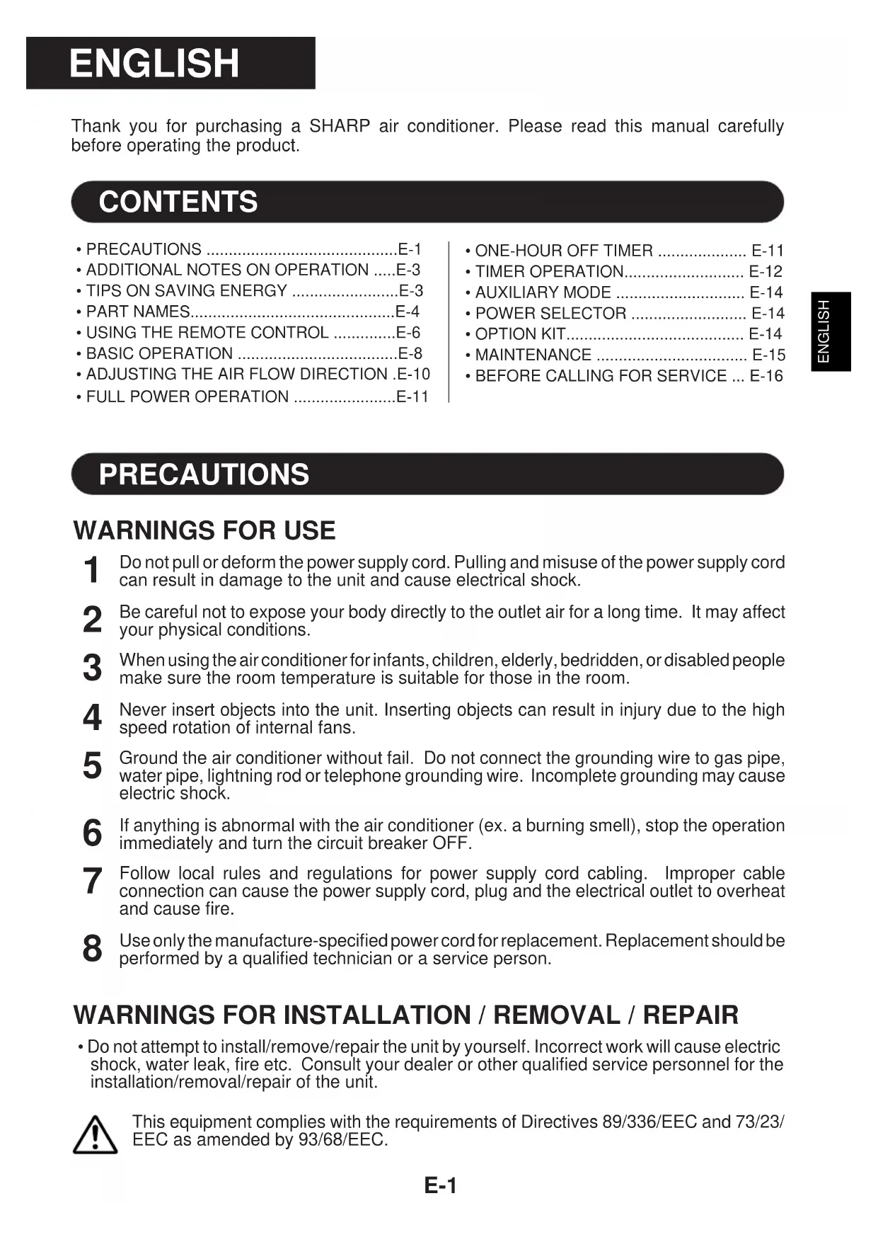
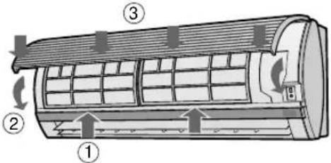
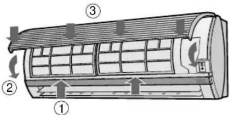
INDOOR UNIT
① Inlet (Air)
② Open Panel
③ Air Filters
④ POWER SELECTOR SWITCH (only for AY-X13BE/AH-X13BE)
⑤ AUX. Button
⑥ RECEIVER Window
⑦ Power Supply Cord
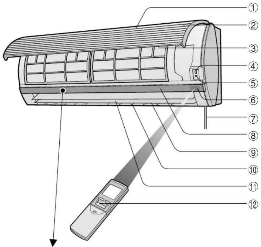
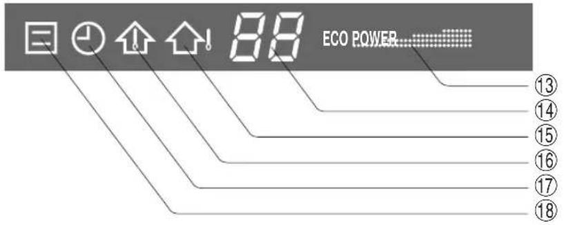
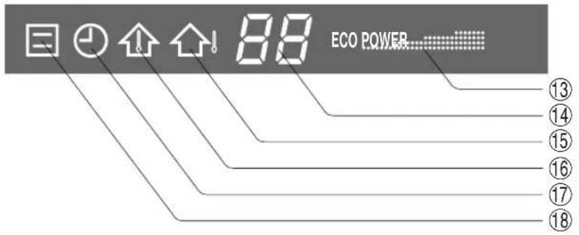
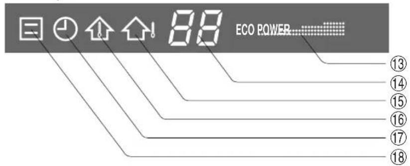
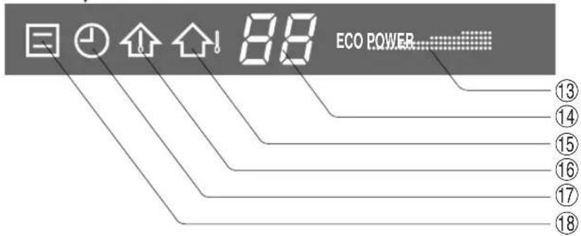
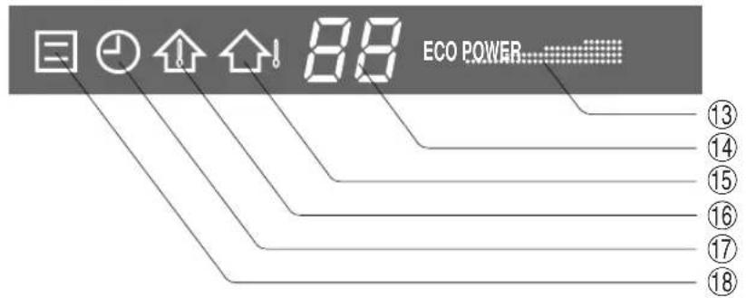
⑧ Indicator Panel
⑨ Vertical Adjustment Louvres
⑩ Horizontal Adjustment Louvres
⑪ Outlet (Air)
⑫ Remote Control
⑬ POWER MONITOR
⑭ TEMPERATURE INDICATOR
⑮ OUTDOOR Temp. Lamp (green ⬆)
⑯ ROOM Temp. Lamp (green
⑰ TIMER Lamp (orange ⏻)
⑱ OPERATION Lamp (red)
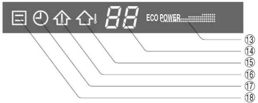
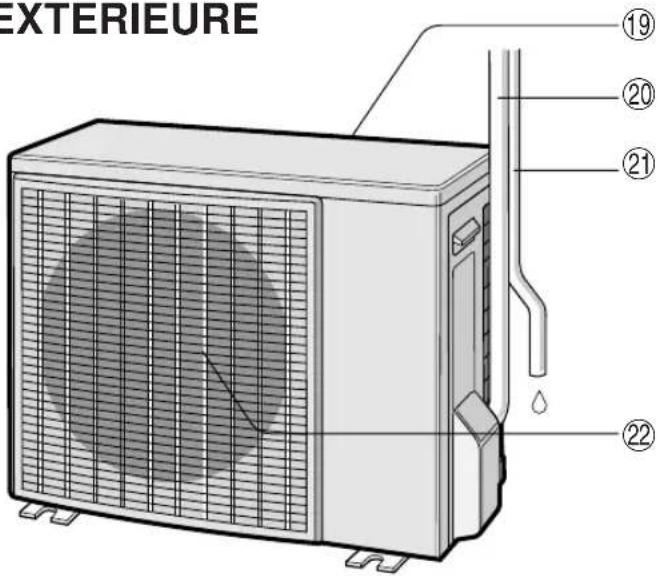
OUTDOOR UNIT
NOTE: Actual units might vary slightly from those shown above.
⑲ Inlet(Air)
⑳ Refrigerant Tube and Interconnecting Cord
②1 Drainage Hose
⑳ Outlet(Air)
REMOTE CONTROL

① TRANSMITTER
② DISPLAY (Liquid Crystal Display)
③ THERMO. (Thermostat) Button
④ FULL POWER OPERATION Button
⑤ DISPLAY Button
⑥ ON/OFF Button
⑦ MODE Button
⑧ FAN Button
⑨ TIMER OFF Button (for setting the timer)
⑩ SWING Button
⑪ ONE-HOUR OFF TIMER Button
⑫ TIMER SET/CANCEL Button
⑬ TIMER ON Button (for setting the timer)
⑭ TIME ADVANCE Button
⑮ CLOCK Button
⑯ Indicates BATTERY COMPARTMENT is below this mark
⑰ TIME REVERSE Button
(The heat mode symbol 🌐s provided only on models AY-X08BE/AY-X10BE/AY-X13BE)
L.C.D. REMOTE CONTROL DISPLAY
⑱ THERMOSTAT SETTING FOR AUTO AND DRY MODES
⑲ TEMPERATURE SYMBOL
⑳ TRANSMITTING SYMBOL
②1 MODE SYMBOLS

: AUTO : DRY


:HEAT:FAN ONLY
(only for AY-X08BE/
AY-X10BE/AY-X13BE)

: COOL
⑳ TEMPERATURE INDICATOR
②3 FULL POWER OPERATION MODE SYMBOL
⑳ FAN SPEED SYMBOLS

: AUTO : LOW


: HIGH : SOFT

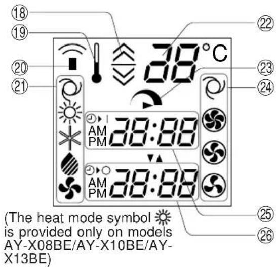
⑲ TIMER ON INDICATOR/CLOCK
Indicates the on timer preset time or current time.
②6 TIMER OFF INDICATOR
Indicates the preset time for off timer or one-hour off timer.
LOADING BATTERIES Use two size-AAA (R03) batteries.
1 Remove the remote control cover.
2 Insert batteries in the compartment, making sure the ⊕ and ⊖ polarities are correctly aligned.
- The display indicates "AM 6:00" when batteries are properly installed.
3 Reinstall the cover.

NOTES:
- The battery life is approximately one year in normal use.
- When you replace the batteries, always change both batteries, and make sure they are the same type.
- If the remote control does not operate properly after replacing the batteries, take out the batteries and reinstall them again after 30 seconds.
- If you will not be using the unit for a long time, remove the batteries from the remote control.
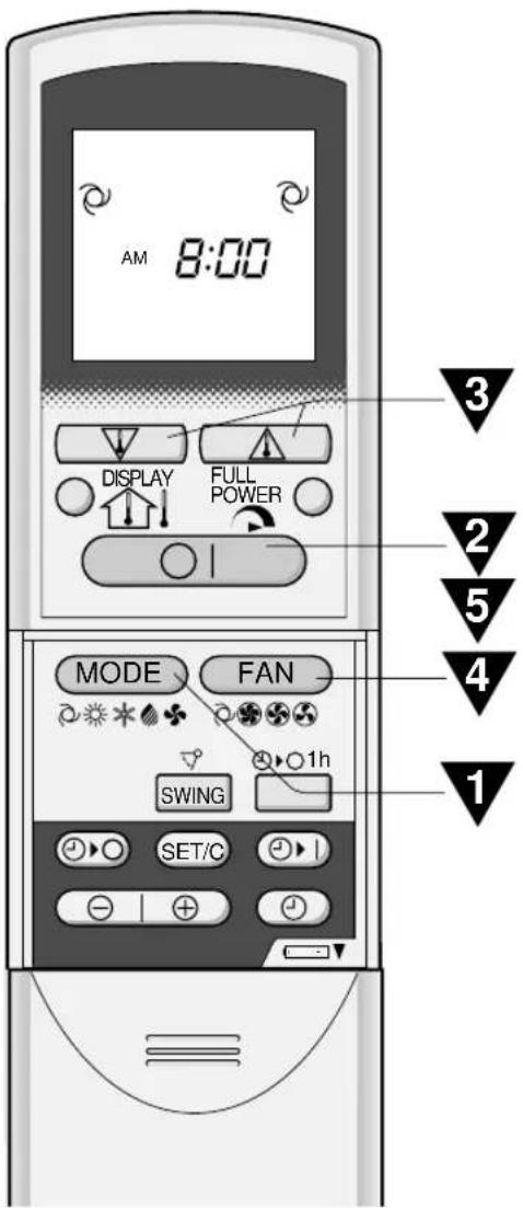
HOW TO USE THE REMOTE CONTROL
Point the remote control towards the unit's signal receiver window and press the desired button. The unit generates a beep when it receives the signal.
- Make sure there is no curtain or other object between the remote control and the unit.
- The remote control can send signals from up to 7 metres away.

natural_image
Illustration of a wall-mounted air conditioner with a digital display and pointer, no text or symbols present
CAUTION
- Do not allow the signal receiver window to receive strong direct sunlight, since it can adversely affect its operation. If the signal receiver window is exposed to direct sunlight, close a curtain to block the light.
- Using a fluorescent lamp with a quick starter in the same room may interfere with transmission of the signal.
- The unit can be affected by signals transmitted from the remote control of a television, VCR or other equipment used in the same room.
- Do not leave the remote control in direct sunlight or near a heater. Also, protect the unit and remote control from moisture and shock which can discolour or damage them.
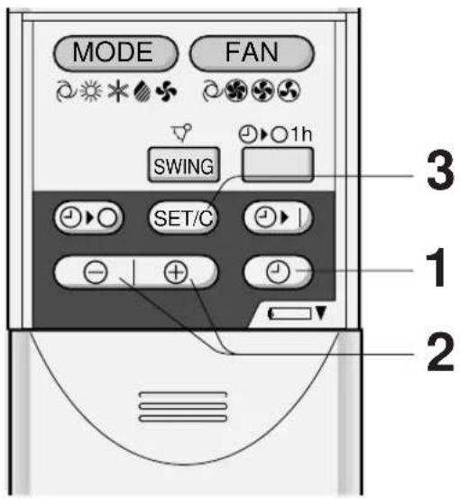
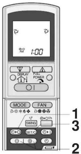
SET CURRENT CLOCK TIME
There are two clock modes: 12-hour mode and 24-hour mode.
(The heat mode symbol 🌿s provided only on models AY-X08BE/AY-X10BE/AY-X13BE)
Example: 5 o'clock in the afternoon
| Clock | Display |
| 12-hour mode PM | 5:00 |
| 24-hour mode 1 | 7:00 |
1 To set to the 12-hour mode, press the CLOCK button once in the first step.
To set to the 24-hour mode, press the CLOCK button twice in the first step.
2 Press the TIME ADVANCE or REVERSE button to set the current time.
- Keep the button pressed to advance or reverse the time display quickly.
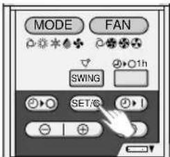
3 Press the SET/C button. • The colon (:) blinks to indicate that the clock is functioning.
NOTE:
- The current time cannot be set when the timer is operating.
(The heat mode symbol 🌿s provided only on models AY-X08BE/AY-X10BE/AY-X13BE)

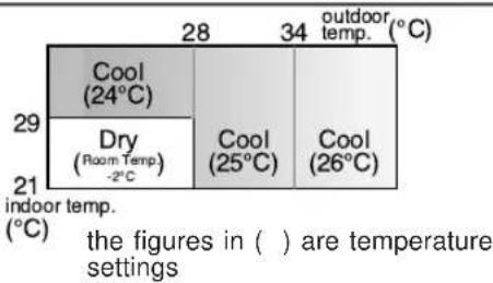
TIPS ABOUT AUTO MODE
In the AUTO mode, the temperature setting and mode are automatically selected according to the room temperature and outdoor temperature when the unit is turned on.
Modes and Temperature Settings for Models AH-X08BE/AH-X10BE/AH-X13BE
heatmap
| indoor temp. (°C) | 28 | 34 | |---|---|---| | 29 | Cool (24°C) | Outdoor temp. (°C) | | 21 | Dry (Room Temp.) -2°C | Outdoor temp. (°C) | | 28 | Cool (25°C) | Outdoor temp. (°C) | | 34 | Cool (26°C) | Outdoor temp. (°C) | The figures in ( ) are temperature settingsModes and Temperature Settings for Models
AY-X08BE/AY-X10BE/AY-X13BE

During operation, if the outdoor temperature changes, the temperature settings will automatically slide as shown in the chart.
MODE CHANGEOVER (only for models AY-X08BE/AY-X10BE/AY-X13BE)
During seasons when you need COOLING at daytime and HEATING at night, or if the room temperature should become extremely higher than the temperature setting, due to supplementary heating equipment, the mode will automatically switch between HEAT and COOL mode to keep the comfortable room temperature.
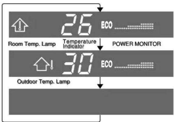
-TIPS ABOUT INDICATOR PANEL
The indicator panel will change each time you press the DISPLAY button in the following manner.
flowchart
graph TD
    A["Room Temp. Lamp"] --> B["26 ECO ..."]
    C["Outdoor Temp. Lamp"] --> D["30 ECO ..."]
    B --> E["POWER MONITOR"]
    D --> E
The room temperature and POWER MONITOR are displayed.
The outdoor temperature and POWER MONITOR are displayed.
No display.
POWER MONITOR
When the room temperature or the outdoor temperature is displayed, the POWER MONITOR will light up in 4 levels (3 levels for DRY mode), to indicate the operation power. When the air conditioner is operating at maximum power in the COOL (and HEAT for AY-X08BE/AY-X10BE/AY-X13BE)mode, "Power" will light and "Eco" will turn off on the indicator panel.
NOTES:
• The displayed temperatures are rough estimates and may vary from the actual temperatures.
• Temperature display ranges
Room temperature: 0°C \~ 40°C (L is displayed when less than 0°C and when higher than 40°C)
Outdoor temperature: -9°C \~ 45°C ( is displayed when less than -9°C and when higher than 45°C)
- -- is displayed during the first minute of operation while the temperatures are being detected.
- Only the room temperature can be displayed when the unit is not in operation.
ADJUSTING THE AIR FLOW DIRECTION
VERTICAL AIR FLOW DIRECTION
The air flow direction is automatically preset in each mode as follows for optimum comfort:
| COOL and DRY mode Horizontal air flow | |
| FAN ONLY (and HEAT for AY-X08BE/AY-X10BE/AY-X13BE) mode | Diagonal air flow |
HOW TO ADJUST THE AIR FLOW DIRECTION
Press the SWING button on the remote control once.
- The vertical adjustment louvre will change its angle continuously.
Press the SWING button again when the vertical adjustment louvre is at the desired position.
- The louvre will stop moving within the range shown in the diagram.
- The adjusted position will be memorized and will be automatically set to the same position when operated the next time.
Adjustment range
COOL and DRY mode
FAN ONLY (and HEAT for AY-X08BE/AY-X10BE/AY-X13BE) mode

The adjustment range is narrower the SWING range in order to prevent condensation from dripping.

The range is wide so the air flow can be directed toward the floor.
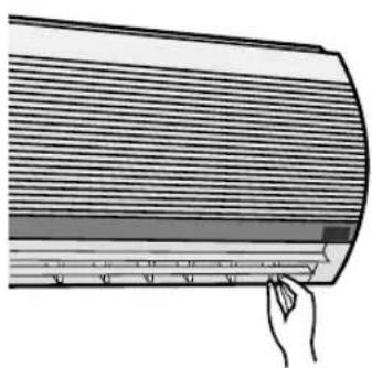
HORIZONTAL AIR FLOW DIRECTION
Hold the horizontal adjustment louvre as shown in the diagram and adjust the air flow direction.
natural_image
Illustration of a hand pressing down on a curved panel with horizontal lines and a shaded band (no text or symbols)
CAUTION
Never attempt to adjust the vertical adjustment louvres manually.
- Manual adjustment of the vertical adjustment louvre can cause the unit to malfunction when the remote control is used for the adjustment.
- When the vertical adjustment louvre is positioned at the lowest position in the COOL or DRY mode for an extended period of time, condensation may result.
In this operation, the air conditioner works at maximum power to makes the room cool (or warm with models AY-X08BE/AY-X10BE/AY-X13BE) so rapidly that you can use it just after you come home.
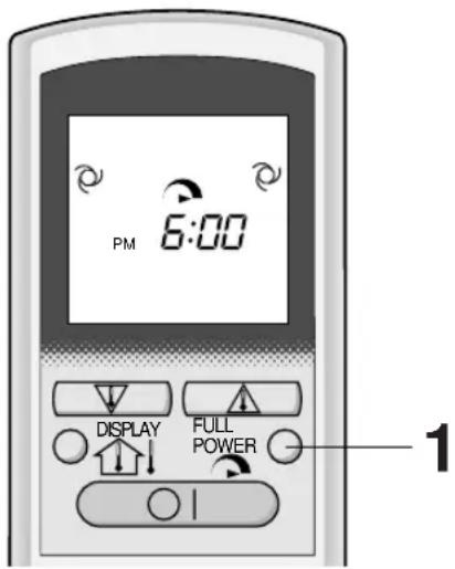
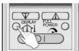
1 To activate the FULL POWER operation, press the FULL POWER button during operation.
- The remote control will display
- the temperature display will go off.
TO CANCEL
Press the FULL POWER button again.
- FULL POWER operation will also be cancelled when the operation mode is changed, or when the unit is turned off.
NOTES:
- You cannot use the FULL POWER operation during the FAN ONLY mode.
- You cannot set the temperature during the FULL POWER operation.
ONE-HOUR OFF TIMER
When the ONE-HOUR OFF TIMER is set, the unit will stop operating after one hour.
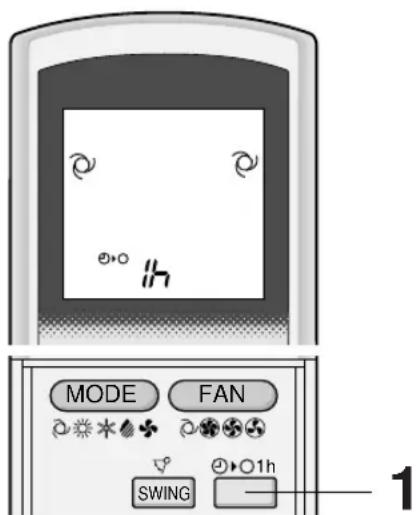
1 Press the ONE-HOUR OFF TIMER button.
- The remote control displays "1 h".
- The orange TIMER lamp ( ⊕ on the unit will light up.
- The unit will stop operating after one hour.
TO CANCEL
Press the TIMER CANCEL (SET/C) button.
- The orange TIMER lamp ( ⊕ on the unit will turn off.
Or, turn the unit off by pressing the ON/OFF button. - The red OPERATION lamp (☐) and the orange TIMER lamp (☐) on the unit will turn off.
(The heat mode symbol ⚙ is provided only on models AY-X08BE/AY-X10BE/AY-X13BE)
NOTES:
- The ONE-HOUR OFF TIMER operation has priority over TIMER ON and TIMER OFF operations.
- When the ONE-HOUR OFF TIMER is set while the unit is not operating, the unit will operate for an hour with the formerly set condition.
- If you wish to operate the unit for another hour before the ONE-HOUR OFF TIMER activates, press the ONE-HOUR OFF TIMER button again during operation.
- If TIMER ON and/or TIMER OFF are set, TIMER CANCEL button cancels every setting.
TIMER OPERATION
NOTE:
Before setting the timer, make sure the clock is properly set with the current time.
TIMER OFF
(The heat mode symbol 🌐s provided only on models AY-X08BE/AY-X10BE/AY-X13BE)
1 Press the TIMER OFF (💡) button.
2 The TIMER OFF indicator will blink; press the TIME ADVANCE or REVERSE buttons to set the desired time. (The time can be set in 10-minute increments.)
3 Point the remote control at the signal receiver window on the unit and press the TIMER SET (SET/C) button.
- The orange TIMER lamp ( ⏻ ) on the unit will light.
- The unit will generate a beep when it receives the signal.
When the TIMER OFF mode is set, the temperature setting is automatically adjusted to prevent the room from becoming excessively hot or too cold while you sleep. (Auto Sleep function)
COOL/DRY MODE:
• One hour after the time operation begins, the temperature setting rises 1^ C higher than the original thermostat setting.
HEAT MODE: (only for models AY-X08BE/AY-X10BE/AY-X13BE)
- One hour after the timer operation begins, the temperature setting drops 3^ lower than the original thermostat setting.
NOTE:
- The Auto Sleep function will not activate during the FAN ONLY mode.
TO CANCEL TIMER MODE
Press the TIMER CANCEL (SET/C) button.
- The orange TIMER lamp ( ⏻ ) on the unit will turn off.
- The current clock time will be displayed on the remote control.
(The heat mode symbol is provided only on models AY-X08BE/AY-X10BE/AY-X13BE)
NOTE:
- If any TIMER ON, TIMER OFF and ONE-HOUR OFF TIMER are set, the TIMER CANCEL button cancels all settings.
TO CHANGE TIME SETTING
Cancel the TIMER setting first, then set it again.
TIMER ON

(The heat mode symbol 🙏 is provided only on models AY-X08BE/AY-X10BE/AY-X13BE)
1 Press the TIMER ON ( ⏻ button.
2 The TIMER ON indicator will blink; press the TIME ADVANCE or REVERSE buttons to set the desired time. (The time can be set in 10-minute increments.)
3 Point the remote control at the signal receiver window on the unit and press the TIMER SET (SET/C) button.
- The orange TIMER lamp ( ⏻ ) on the unit will light.
- The unit will generate a beep when it receives the signal.
4 Select the operation condition.
- The unit will turn on prior to the set time to allow the room to reach the desired temperature by the programmed time. (Awaking function)
COMBINED USE OF ON AND OFF TIMERS
You can use the ON and OFF timers in combination.

Example:
To stop operation at 11:00 p.m. and resume operation (With the same mode and temperature settings) to bring the room temperature to the desired level by 7:00 a.m.
1 Set the TIMER OFF to 11:00 p.m. during operation.
2 Set the TIMER ON to 7:00 a.m.
The arrow (▼ or ▲) between the TIMER ON indicator and the TIMER OFF indicator shows which timer will activate first.
NOTES:
- You cannot programme the ON-TIMER and OFF-TIMER to operate the unit at different temperatures or other settings.
- Either timer can be programmed to activate prior the other.
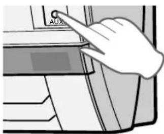
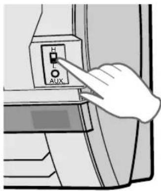
AUXILIARY MODE
Use this mode when the remote control is not available.
TO TURN ON
Lift the front panel of the indoor unit and press the AUX. button on the operation panel.
- The red OPERATION lamp (☐) on the unit will light and the unit will start operating in the AUTO mode.
- The fan speed and temperature setting are set to AUTO.
TO TURN OFF
Press the AUX. button on the operation panel again.
- The red OPERATION lamp ( ☐ ) on the unit will turn off.
NOTE:
If the AUX. button is pressed during normal operation, the unit will turn off.
POWER SELECTOR (only for models AY-X13BE/AH-X13BE)
When installing the air-conditioner to a residence with small electrical current capacity, switch the POWER SELECTOR to "L". The air conditioner will operate with reduced power, and the circuit breaker tripping or fuse blowing caused by excess power consumption can be avoided.
- COOLING or HEATING (for model AY-X13BE) capacity will be reduced when operating at "L" setting.
- Consult your dealer or qualified technician if continuous breaker tripping or fuse blowing is experienced even by switching to "L" setting.
| AH-X13BE AY-X13BE | |
| Maximum ampere at "H" setting | 9A 12A |
| Maximum ampere at "L" setting | 7A 8A |
OPTION KIT
Air Purifying Filter
During operation of the air conditioner, the air purifying filter removes dust and tobacco smoke from the air and discharges clean air.
The apatite antibacterial material used in the air purifying filter suppresses activities of adsorbed viruses and other germs.
The replacement period for the disposable type is approximately 3\~6 months.
Contact your dealer for the purchase of this option.

natural_image
3D illustration of a two-layered rectangular block (no text or symbols)Type AZ-F900B
CAUTION
Be sure to disconnect the power cord from the wall outlet or turn off the circuit breaker before performing any maintenance.
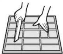
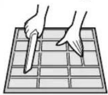
CLEANING THE FILTERS
The air filters should be cleaned every two weeks.
natural_image
Illustration of two hands using a tool to cut a grid on a 3x3 grid (no text or symbols)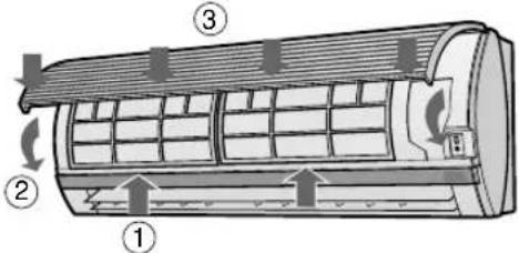
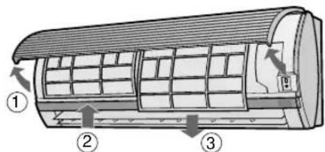
1 TURN OFF THE UNIT
2 REMOVE THE FILTERS
1 Lift the open panel.
2 Push the air filters up slightly to unlock them.
3 Pull the air filters down to remove them.
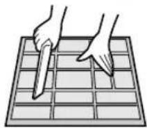
3 CLEAN THE FILTERS
Use a vacuum cleaner to remove dust. If the filters are dirty, wash them with warm water and a mild detergent. Dry filters in the shade before reinstalling.
4 REINSTALL THE FILTERS
1 Reinstall the filters in the original positions.
2 Close the front panel.
3 Push the center part of the panel firmly to lock it in place.
CLEANING THE UNIT AND THE REMOTE CONTROL
CAUTION
- Wipe them with a soft cloth.
- Do not directly splash or pour water on them. We can cause electrical shock or equipment damage.
- Do not use hot water, thinner, abrasive powders or strong solvents.
MAINTENANCE AFTER AIR CONDITIONER SEASON
1 Operate the unit in the FAN ONLY mode for about half a day to allow the mechanism to thoroughly dry.
2 Stop the operation and unplug the unit. Turn off the circuit breaker, if you have one exclusively for the air conditioner.
3 Clean the filters, then reinstall them.
MAINTENANCE BEFORE AIR CONDITIONER SEASON
1 Make sure that the air filters are not dirty.
2 Make sure that nothing obstructs the air inlet or outlet.
CAUTION
3 Check the outdoor mounting rack periodically for wear and to make sure it is firmly in place.
BEFORE CALLING FOR SERVICE
The following conditions do not denote equipment malfunctions
| UNIT DOES NOT OPERATEThe unit will not operate if it is turned on immediately after it is turned off. The unit will not operate immediately after the mode is changed. This is to protect the internal mechanisms. Wait 3 minutes before operating the unit. | SWISHING NOISEThe soft, swishing noise is the sound of the refrigerant flowing inside the unit. |
| WATER VAPOURIn the COOL and DRY operation, water vapour can sometimes be seen at the air outlet due to the difference between the room air temperature and the air discharged by the unit.In the HEAT operation, water vapour may flow out of the outdoor unit during de-icing. (Only in models AY-X08BE/AY-X10BE/AY-X13BE) | |
| UNIT DOES NOT SEND OUT WARM AIR (Models AY-X08BE/AY-X10BE/AY-X13BE)The unit is preheating or de-icing. | |
| ODORSCarpet and furniture odors that entered into the unit and the air conditioner's inner component odors at the early stage of installation may be sent out from the unit. | |
| CRACKING NOISEThe unit may produce a cracking noise. This sound is generated by the friction of the front panel and other components expanding or connecting due to a temperature change. | THE OUT DOOR UNIT DOES NOT STOPAfter stopping the operation, the outdoor unit will rotate its' fan for about a minute to cool down the unit. |
If the unit appears to be malfunctioning, check the following points before calling for service.
| IF THE UNIT FAILS TO OPERATE |
| Check to see if the circuit breaker has tripped or the fuse has blown. |
| IF THE UNIT FAILS TO COOL (OR HEAT) THE ROOM EFFECTIVELY | ||
| Check the filters. If dirty, clean them. | Check the outdoor unit to make sure nothing is blocking the air inlet or outlet. | Check the thermostat is proper setting. |
| Make sure windows and doors are closed tightly. | A large number of people in the room can prevent the unit from achieving the desired temperature. | Check whether any heat-generating appliances are operating in the room. |
| IF THE UNIT FAILS TO RECEIVE THE REMOTE CONTROL SIGNAL | ||
| Check whether the remote control batteries have become old and weak. | Try to send the signal again with the remote control pointed properly towards the unit's signal receiver window. | Check whether the remote control batteries are installed with the polarities properly aligned. |
Please call for service when OPERATION Lamp, TIMER Lamp and TEMPERATURE INDICATOR on the indicator panel blink.

AUSSENGERÄT

natural_image
Illustration of a wall-mounted air conditioner with a digital display and pointer, no text or symbols present
VORSICHT
natural_image
Illustration of a hand holding a fan blade with a striped pattern (no text or symbols)
VORSICHT
natural_image
3D illustration of a layered rectangular material with textured surface (no text or symbols)Typ AZ-F900B
VORSICHT
natural_image
Illustration of hands using a tool to cut or spread a grid on a 3x3 grid (no text or symbols)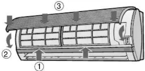
1 SCHALTEN SIE DAS GERÄT AUS
2 ENTNEHMEN SIE DIE FILTER
MISES EN GARDE POUR L'INSTALLATION/LA DEPOSE/LA REPARATION
D.B. = Sec W.B. = Humide
EN CAS DE PANNE DE COURANT

UNITE EXTERIEURE
natural_image
Illustration of a wall-mounted air conditioner with a digital display and pointer, no text or symbols present
ATTENTION
heatmap
| Temperature (°C) | Ventilateur | Chauf-fage (24°C) | Chauf-fage (23°C) | Climatisation (24°C) | Climatisation (25°C) | Climatisation (26°C) | |---|---|---|---|---|---|---| | 0 | | | | | | | | 10 | | | | | | | | 18 | | | | | | | | 28 | | | | | | | | 34 | | | | | | | | Temp. extérieure (°C) | | | | | | | | 29 | Ventilateur | Chauffage (23°C) | Chauffage (23°C) | Sec (temp. ambiante) -2°C | | | | 21 | | | | Chauffage (22°C) | | | The chart is a grid of color-coded cells representing the temperature ranges for each component. The values in the cells are estimated based on the numerical labels inside the cells.natural_image
Illustration of a hand holding a small object near a curved surface (no text or symbols)
ATTENTION
Exemple :
natural_image
3D illustration of a layered rectangular block with textured top surface (no text or symbols)Type AZ-F900B
ATTENTION

natural_image
Illustration of hands using a tool to cut or mark a grid pattern (no text or symbols)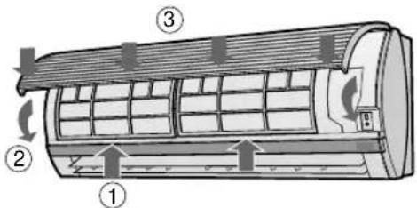
1 ETEINDRE L'APPAREIL
2 ENLEVER LES FILTRES
natural_image
Illustration of a wall-mounted air conditioner with a digital display and pointer, no text or symbols present
PRECAUCIÓN
flowchart
graph LR
    A["AUTO"] --> B["ALTA"]
    B --> C["BAJA"]
    C --> D["SUAVE"]
natural_image
Illustration of a hand pressing down on a curved panel with horizontal lines and a shaded band (no text or symbols)
PRECAUCIÓN
natural_image
3D illustration of a layered rectangular material with textured surface (no text or symbols)Tipo AZ-F900B
PRECAUCIÓN

natural_image
Illustration of two hands using a tool on a grid-patterned surface (no text or symbols)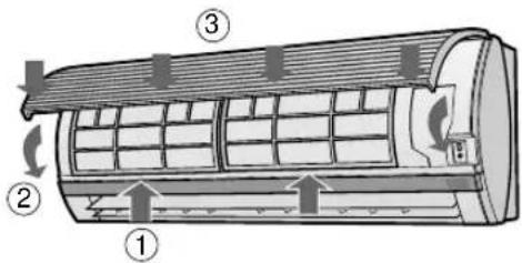
1 DESCONECTE LA UNIDAD
2 SAQUE LOS FILTROS
natural_image
Illustration of a wall-mounted air conditioner with a digital display and pointer, no text or symbols present
PRECAUZIONI
natural_image
Illustration of a hand holding a rolled-up sheet of paper with horizontal lines and a shaded band (no text or symbols)
PRECAUZIONI
natural_image
3D illustration of a layered rectangular block with textured surfaces (no text or symbols)Tipo AZ-F900B
PRECAUZIONE
natural_image
Illustration of hands using a tool to cut or spread on a grid (no text or symbols)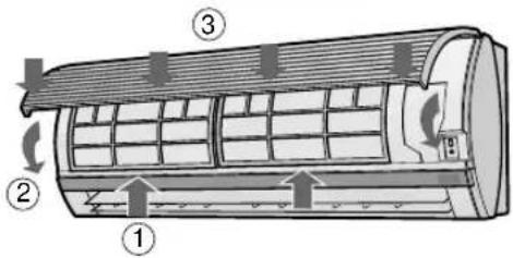
1 SPEGNETE L'UNITA'
2 RIMUOVETE I FILTRI

NOTAS:
natural_image
Illustration of a wall-mounted air conditioner with a digital display and a pointer emitting light (no text or symbols)
ATENÇÃO
(O símbolo do modo AQUECER aparece apenas nos modelos AY-X08BE/AY-X10BE/AY-X13BE)
(O símbolo do modo AQUECER aparece apenas nos modelos AY-X08BE/AY-X10BE/AY-X13BE)

natural_image
Illustration of a hand pressing down on a curved surface with horizontal lines and a shaded band (no text or symbols)
ATENÇÃO
(O símbolo de AQUECER aparece apenas nos modelos AY-X08BE/AY-X10BE/AY-X13BE)
1 Carregue no botão TEMPORIZADOR DE UMA HO-RA (ONE-HOUR OFF TIMER).
(O símbolo de AQUECER aparece apenas nos modelos AY-X08BE/AY-X10BE/AY-X13BE)
(O símbolo do modo AQUECER aparece apenas nos modelos AY-X08BE/AY-X10BE/AY-X13BE)
NOTA:
- De qualquer modo se o LIGAR TEMPORI-ZADOR (TIMER ON), DESLIGAR TEMPORI-ZADOR (TIMER OFF) e TEMPORIZADOR DE UMA HORA (ONE-HOUR OFF TIMER) estiver activado, o botão de ANULAR TEMPO-RIZADOR (TIMER CANCEL) cancela todos os ajustamentos.
PARA MODIFICAR A HORA
(O símbolo de AQUECER aparece apenas nos modelos AY-X08BE/AY-X10BE/AY-X13BE)
Exemplo:
natural_image
3D illustration of a layered rectangular material with textured surface (no text or symbols)Tipo AZ-F900B
ATENÇÃO

natural_image
Illustration of two hands using a tool on a grid-patterned surface (no text or symbols)
DESLIGAR A UNIDADE
2 RETIRAR OS FILTROS
natural_image
Illustration of a wall-mounted air conditioner with a digital display and pointer, no text or symbols present
ΠΡΟΣΟΧΗ
natural_image
Illustration of a hand pressing down on a curved panel with horizontal stripes (no text or symbols)
ΠΡΟΣΟΧΗ
natural_image
Stack of three rectangular panels with textured surfaces, no text or symbols visibleTùnòσ AZ-F900B
ΠΡΟΣΟΧΗ
WAARSCHUWINGEN BIJ DE PLAATSING / INSTALLATIE
natural_image
Illustration of a wall-mounted air conditioner with a digital display and pointer, no text or symbols present
LET OP
natural_image
Illustration of a hand pressing down on a curved panel with horizontal stripes (no text or symbols)
LET OP
KOELEN/DROGEN-FUNCTIE:
Voorbeeld:
natural_image
Stack of three rectangular panels with textured surfaces, no text or symbols visibleType AZ-F900B
LET OP
1 SCHAKEL HET TOESTEL UIT
2 VERWIJDER DE FILTERS
natural_image
Illustration of hands using a tool to cut a grid on a tiled surface (no text or symbols)4 PLAATS DE FILTERS TERUG
natural_image
Illustration of a wall-mounted air conditioner with a digital display and pointer, no text or symbols present
UYARI
natural_image
Illustration of a hand pressing down on a curved panel with horizontal stripes (no text or symbols)
UYARI
BİR SAAT SONRA KAPANMA AYARI
natural_image
3D illustration of a layered rectangular material with a textured top layer (no text or symbols)Tip AZ-F900B
UYARI

1 ÜNİTEYİ KAPATIN
2 FILTRELERİ ÇIKARIN

- CONTENTS
- PRECAUTIONS
- WARNINGS FOR USE
- WARNINGS FOR INSTALLATION / REMOVAL / REPAIR
- CAUTIONS FOR USE
- CAUTIONS FOR LOCATION / INSTALLATION
- ADDITIONAL NOTES ON OPERATION
- WHEN POWER FAILURE OCCURS
- NOTES FOR MODELS AY-X08BE/AY-X10BE/AY-X13BE
- PREHEATING FUNCTION
- DE-ICING FUNCTION
- HEATING EFFICIENCY
- TIPS ON SAVING ENERGY
- SET THE CORRECT TEMPERATURE
- BLOCK DIRECT SUNLIGHT AND PREVENT DRAFTS
- SET PROPER AIR FLOW DIRECTION TO OBTAIN THE BEST AIR CIRCULATION
- KEEP FILTER CLEAN TO ENSURE THE MOST EFFICIENT OPERATION MAKE MOST OF THE TIMER OFF FUNCTION
- DISCONNECT THE POWER CORD WHEN THE UNIT IS NOT USED FOR AN EXTENDED PERIOD OF TIME
- L.C.D. REMOTE CONTROL DISPLAY
- LOADING BATTERIES Use two size-AAA (R03) batteries.
- NOTES:
- HOW TO USE THE REMOTE CONTROL
- CAUTION
- SET CURRENT CLOCK TIME
- NOTE:
- TIPS ABOUT AUTO MODE
- MODE CHANGEOVER (only for models AY-X08BE/AY-X10BE/AY-X13BE)
- -TIPS ABOUT INDICATOR PANEL
- POWER MONITOR
- ADJUSTING THE AIR FLOW DIRECTION
- VERTICAL AIR FLOW DIRECTION
- HOW TO ADJUST THE AIR FLOW DIRECTION
- Adjustment range
- HORIZONTAL AIR FLOW DIRECTION
- TO CANCEL
- ONE-HOUR OFF TIMER
- TIMER OPERATION
- TIMER OFF
- COOL/DRY MODE:
- HEAT MODE: (only for models AY-X08BE/AY-X10BE/AY-X13BE)
- TO CANCEL TIMER MODE
- TO CHANGE TIME SETTING
- TIMER ON
- COMBINED USE OF ON AND OFF TIMERS
- Example:
- AUXILIARY MODE
- TO TURN ON
- TO TURN OFF
- POWER SELECTOR (only for models AY-X13BE/AH-X13BE)
- OPTION KIT
- Air Purifying Filter
- CLEANING THE FILTERS
- CLEANING THE UNIT AND THE REMOTE CONTROL
- MAINTENANCE AFTER AIR CONDITIONER SEASON
- MAINTENANCE BEFORE AIR CONDITIONER SEASON
- BEFORE CALLING FOR SERVICE
- VORSICHT
- MISES EN GARDE POUR L'INSTALLATION/LA DEPOSE/LA REPARATION
- EN CAS DE PANNE DE COURANT
- ATTENTION
- Exemple :
- PRECAUCIÓN
- DESCONECTE LA UNIDAD
- SAQUE LOS FILTROS
- PRECAUZIONI
- PRECAUZIONE
- NOTAS:
- ATENÇÃO
- NOTA:
- PARA MODIFICAR A HORA
- Exemplo:
- DESLIGAR A UNIDADE
- RETIRAR OS FILTROS
- ΠΡΟΣΟΧΗ
- WAARSCHUWINGEN BIJ DE PLAATSING / INSTALLATIE
- LET OP
- KOELEN/DROGEN-FUNCTIE:
- Voorbeeld:
- UYARI
- BİR SAAT SONRA KAPANMA AYARI
Brand : SHARP
Model : AHX10BE
Category : Air conditioner