
One 140 - Air Conditioning DELONGHI - Free user manual and instructions
Find the device manual for free One 140 DELONGHI in PDF.
| Product type | Reversible air conditioner (heat pump) |
| Brand | DeLonghi |
| Model | One 140 (One series) |
| Power supply | 230 V ~ 50 Hz |
| Refrigerant gas type | R410A (GWP 1975) |
| Indoor unit dimensions (W x H x D) | 770 x 250 x 205 mm (7-9K model) |
| Outdoor unit dimensions (W x H x D) | 763 x 515 x 258 mm (7-9K model) |
| Indoor unit net weight | 8 kg |
| Outdoor unit net weight | 30 kg (ON-OFF 7-9K model) |
| Operating modes | Cooling, Heating, Dehumidification, Ventilation, SMART (auto), SLEEP |
| Special functions | TURBO, I COMFORT, Timer 24h, Swing, Light, Hot Start |
| Remote control | Yes, with LCD display and AAA batteries |
| Air filter | Washable with water (≤45°C) |
| Optional filters | Antibacterial silver ion filter, electrostatic deodorizing filter (non-washable, replace every 6 months) |
| Maintenance | Regular filter cleaning, disconnect power before any operation |
| Safety | High/low pressure protection, overload, automatic shutdown in case of anomaly |
| Repairability | Only to be entrusted to DeLonghi authorized Technical Assistance Centers |
| Max piping length | 25 m (depending on model) |
| Air flow | 3 speeds + AUTO |
| Temperature range | Cooling: 16-30°C / Heating: 16-30°C |
Frequently Asked Questions - One 140 DELONGHI
User questions about One 140 DELONGHI
0 question about this device. Answer the ones you know or ask your own.
Ask a new question about this device
Download the instructions for your Air Conditioning in PDF format for free! Find your manual One 140 - DELONGHI and take your electronic device back in hand. On this page are published all the documents necessary for the use of your device. One 140 by DELONGHI.
USER MANUAL One 140 DELONGHI
OPERATING AND INSTALLATION MANUAL

ONEinverter
I) CONDIZIONATORI D'ARIA E POMPDA DI CALORE SINGLE SPLIT ON-OFF E DC INVERTER
EN) SINGLE SPLIT DC INVERTER AND ON-OFF AIR CONDITIONERS AND HEAT PUMP
FR) CONDITIONNEURS D'AIR ET POMPE À CHALEUR SINGLE SPLIT ON-OFF ET DC INVERTER
DE) KLIMAANLAGEN UND WARMEPUMPEN SINGLE SPLIT ON-OFF UND DC INVERTER
ES) ACONDITIONADOS DE AIRE Y BOMBA DE CALOR SINGLE SPLIT DC INVERTERY ON-OFF
PT) CONDICIONADORES DE ARE BOMBA DE CALOR SINGLE SPLIT ON-OFF E DC INVERTER
NL) AIRCONDITIONERS EN WARMTEPOMP SINGLE SPLIT DC INVERTER EN ON-OFF
RU) KOHДицИОHEРы C TENПОБыIM HACOCOM MONO SPLIT DC INVERTER I ON-OFF
EL) KAIIMATI STIKA KAI ANTAIA ΘEPMOTHTA SINGLE SPLIT DC INVERTER KAI ON-OFF
PL) KLIMATYZATOR POWIETRZA I POMPACIEPLA TYPUSINGLE SPLITZSYSTEMEMDC INWERTERIONOFF
HU) ON/OFF ES DC INVERTERES SZABÁLYOZÁSOS MONOSPLIT LÉG K O N D I C I O N A L O BERENDEZÉSEK ES HÖSZIVATTYU
CS) KLMIATIZACNI ZARIZENI A TEPELNE CERPADLO SINGLE SPLIT ON-OFF A DC INVERTER

Living innovation
Cod. 571731003I, Rev. 00 (11/2007), Page: 20

Thank you for having chosen a
ONE or condition is an innovative,
high quality product designed to ensure your wellbeing.
This instruction booklet contains important information and recommendations that we would ask you to comply with to obtain best results from your air conditioner.
We thank you once again.
Delonghi.
In line with the company's policy of continual product improvement, the aesthetic and dimensional characteristics, technical data and accessories of this appliance may be changed without notice.
CONTENTS
GENERAL INFORMATION
GENERAL INFORMATION Page.
Conformity and range
Safety rules and recommendations for the installer ....2
Safety rules and recommendations for the user 2
Safety rules and prohibitions 3
Names of the parts 3
Technical data 4
USER Page.
Operation and EEC
(Electronic Climate Control) display 6
Remote control 6
Modes of operation 8
COOLING mode. 9
HEATING mode 9
TIMER mode 9
FAN mode 10
DRY mode 10
SMART mode 10
SLEEP mode
I COMFORT function
ROOM TEMPERATURE function.
TURBO POWER function
LIGHT function 12
Another functions 12
INSTALLER Page.
Handling 13
Installing the indoor unit 13
Installing the outdoor unit 16
Bleeding. 17
Maintenance 17
Possible errors 18
Troubleshooting 19
Disposal. 20
Environmental information 20
Extra refrigerant charge 20
Useful information 20
CONFORMITY AND RANGE
GENERAL INFORMATION
The air conditioner you have purchased is in conformity with the following European Directives:
Low Voltage 73/23/EEC
Electromagnetic compatibility 89/336/EEC
| ONE ON-OFF Model | ONE Inverter Model |
| ONE On-Off 7K ONE | Inverter 9K |
| ONE On-Off 9K ONE | Inverter 12K |
| ONE On-Off 12K ONE | Inverter 18K |
| ONE On-Off 18K ONE | Inverter 24K |
| ONE On-Off 24K |
CE
Code 5717310031, Rev. 00 (11/2007), Pages: 20

Read this guide before installing and using the appliance.

Check that air cannot enter the refrigerant system and check for refrigerant leaks when moving the air conditioner.

Carry out a test cycle after installing the air conditioner and record the operating data.

The ratings of the fuse installed in the built-in control unit are 2.5 A, E, 250V.

The user must ensure that the whole unit is protected by a fuse of adequate capacity in relation to the maximum input current or by another overload protective device.

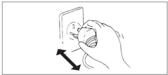
Ensure that the mains voltage corresponds to that stamped on the rating plate. Keep the switch or power plug clean. Insert the power plug correctly and firmly into the socket, thereby avoiding the risk of electric shock or fire due to insufficient contact.

Check that the socket is suitable for the plug, otherwise have the socket changed.

Make sure that the base of the outdoor unit is firmly fixed.

Do not install the appliance at a distance of less than 50~cm from inflammable substances (alcohol, etc.) or from pressurised containers (e.g. spray cans).

If the appliance is used in areas without the possibility of ventilation, precautions must be taken to prevent any leaks of refrigerant gas from remaining in the environment and creating a danger of fire

The packaging materials are recyclable and should therefore be disposed of in the relative separate waste bins. Take the air conditioner at the end of its useful life to a special waste collection centre for disposal.

Only use the air conditioner as instructed in this booklet. These instructions are not intended to cover every possible condition and situation. As with any electrical household appliance, common sense and caution are therefore always recommended for installation, operation and maintenance.

The appliance must be installed in accordance with applicable national regulations.

Before accessing the terminals, all the power circuits must be disconnected from the power supply.
SAFETY RULES AND RECOMMENDATIONS FOR THE USER
GENERAL INFORMATION

Ensure that the mains voltage corresponds to that stamped on the rating plate. Keep the switch or power plug clean. Insert the power plug correctly and firmly into the socket, thereby avoiding the risk of electric shock or fire due to insufficient contact.

Do not pull out the plug to switch off the appliance when it is in operation, since this could create a spark and cause a fire, etc.

The user is responsible for having the appliance installed by a qualified technician, who must check that it is earthed in accordance with current legislation and insert a thermomagnetic circuit breaker.

Prolonged exposure to cold air is harmful to health.

If the appliance gives off smoke or there is a smell of burning, immediately cut off the power supply and contact the Service Centre.

Have repairs carried out only by an authorised Service Centre of the manufacturer. Incorrect repair could expose the user to the risk of electric shock, etc.

Ensure that the appliance is disconnected from the power supply when it will remain inoperative for a long period and before carrying out any cleaning or maintenance.

This appliance must only be used by adults; do not allow children or persons with reduced psychophysical-sensorial abilities to use it.

Selecting the most suitable temperature can prevent damage to the appliance.

The airflow direction must be properly adjusted. The flaps must be directed downwards in the heating mode and upwards in the cooling mode.

This appliance has been made for air-conditioning domestic environments and must not be used for any other purpose, such as for drying clothes, cooling food, etc.

The packaging materials are recyclable and should therefore be disposed of in the relative separate waste bins. Take the air conditioner at the end of its useful life to a special waste collection centre for disposal.

Only use the air conditioner as instructed in this booklet. These instructions are not intended to cover every possible condition and situation. As with any electrical household appliance, common sense and caution are therefore always recommended for installation, operation and maintenance.

Cleaning and maintenance must be carried out by specialised technical personnel. In any case disconnect the appliance from the mains electricity supply before carrying out any cleaning or maintenance.

Do not bend, tug or compress the power cord since this could damage it. Electrical shocks or fire are probably due to a damaged power cord.
Specialised technical personnel only must replace a damaged power cord.

Do not use extensions or gang modules.

Do not touch the appliance when barefoot or parts of the body are wet or damp.

Do not obstruct the air inlet or outlet of the indoor or the outdoor unit.

In no way alter the characteristics of the appliance.

Do not install the appliance in environments where the air could contain gas, oil or sulphur or near sources of heat.

Do not climb onto or place any heavy or hot objects on top of the appliance.

Do not leave windows or doors open for long when the air conditioner is operating.

Do not direct the airflow onto plants or animals.

Do not spray water onto the air conditioner.

Do not climb onto or place any objects on the outdoor unit

Never insert a stick or similar object into the appliance. It could cause injury.
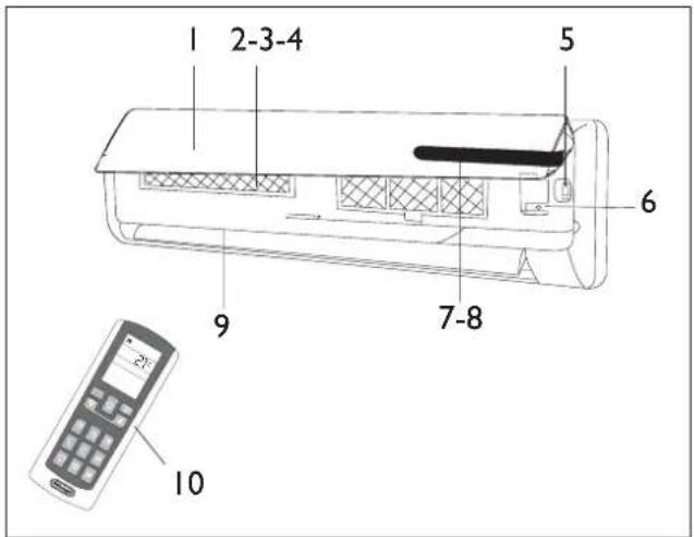
NAMES OF THE PARTS
GENERAL INFORMATION
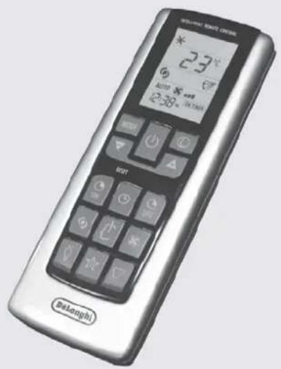
INDOOR UNIT
No. Description
I Front panel
2 Air filter
3 Antibacterial silver ion filter (if installed)
4 Deodoriser biologic electrostatic filter (if installed)
5 Terminal block cover
6 Automatic restart button
7 ECC LED display
8 Signal receiver
9 Airflow direction flaps
10 Intelligent remote control
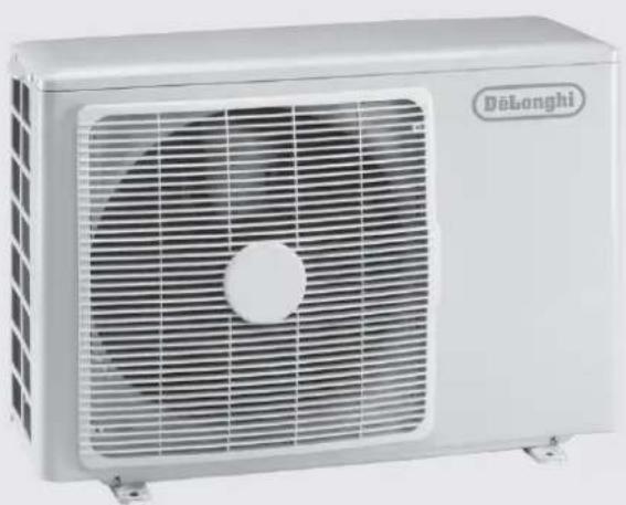
OUTDOOR UNIT
No. Description
I Air outlet grille
12 Handle
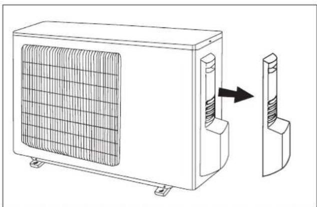
13 Fittings cover (if present)
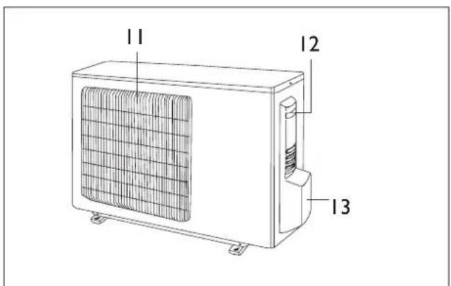
Note: the above figures are only intended to be a simple diagram of the appliance and may not correspond to the appearance of the units that have been purchased.
| INverter MODELS | 9K 12K | 18K 24K | ||||
| General data | ||||||
| Electricity supply 230~50 (*) V~Hz | ||||||
| Refrigerant gas R410 A (**) | ||||||
| Fuse 10 15 15 15 A | ||||||
| Minimum cable section 1,5 2,5 2,5 2,5 mm | 2 | |||||
| Size and clearance | ||||||
| L H P A E D C ↓ | L 770 | 830 1020 1020 mm | ||||
| H 250 | 285 310 310 mm | |||||
| P 205 | 215 250 250 mm | |||||
| A | 150 | mm | ||||
| B | 150 | mm | ||||
| C | 2500 | mm | ||||
| D | 150 | mm | ||||
| E | 300 | mm | ||||
| L P H E D C ↓ | L 763 | 763 848 848 mm | ||||
| P 258 | 258 378 378 mm | |||||
| H 515 | 515 620 620 mm | |||||
| C | 300 | mm | ||||
| D | 500 | mm | ||||
| F | 300 | mm | ||||
| E | 2000 | mm | ||||
| Indoor unit net weight | 8 | 11 14 14 kg | ||||
| Outdoor unit net weight | 40 40 52 52 kg | |||||
| Connecting pipes | ||||||
| Refrigerant pipe size | Liquid | 6,0 - 1/4" | 6,0 - 1/4" | 6,0 - 1/4" | 10-3/8" | Ø-inch |
| Gas | 12 - 1/2" | 12 - 1/2" | 12 - 1/2" | 16-5/8" | Ø-inch | |
| Pipe tightening torque | Liquid | 20 20 20 40 | Nm | |||
| Gas | 60 60 60 80 | Nm | ||||
| Quantity of refrigerant per metre of pipe (over 5 m) | 15 | 15 | 22 | 22 | g/m | |
| A B C | A (max) | 6 | 6 | 8 | 8 | m |
| B (max) | 25 25 30 30 m | |||||
| C (max) | 6 | 6 | 8 | 8 | m | |
| Refrigerant charge | (*) | g. | ||||
| Operating limits | ||||||
| Internal part bulb Exte | nal part bulb | |||||
| Cooling (Max ; Min) | 36 ; 16 | 45 ; -10 | °C | |||
| Heating (Max ; Min) | 30 ; 16 | 27 ; -15 | °C | |||
() See the rating plate for the electricity supply.
() The appliance may be supplied with refrigerant gas R22 in countries where the use of refrigerant gas R410a is not compulsory.
(See the rating plate for the refrigerant charge.
| ON-OFF MODELS | 7K 9K | 12K 18K | 24K | ||||
| General data | |||||||
| Electricity supply 230~50 (*) V~Hz | |||||||
| Refrigerant gas R410 A (**) | |||||||
| Fuse 10 10 15 15 15 A | |||||||
| Minimum cable section 1,5 1,5 2,5 2,5 mm | 2 | ||||||
| Size and clearance | |||||||
| L H P A E D C H | L 770 | 770 830 | 1020 | 1020 mm | |||
| H | 250 250 | 285 310 | 10 mm | ||||
| P 205 | 205 215 | 250 mm | |||||
| A | 150 | mm | |||||
| B | 150 | mm | |||||
| C | 2500 | mm | |||||
| D | 150 | mm | |||||
| E | 300 | mm | |||||
| L P H | L 763 | 763 763 | 848 950 mm | ||||
| P 258 | 258 258 | 378 420 mm | |||||
| H | 515 515 | 515 620 | 40 mm | ||||
| C | 300 | mm | |||||
| D | 500 | mm | |||||
| F | 300 | mm | |||||
| E | 2000 | mm | |||||
| Indoor unit net weight | 8 | 8 | 11 14 | 5 kg | |||
| Outdoor unit net weight | 30 30 | 38 52 72 kg | |||||
| Connecting pipes | |||||||
| Refrigerant pipe size | Liquido | 6,0 - 1/4" | 6,0 - 1/4" | 6,0 - 1/4" | 6,0 - 1/4" | 10-3/8" | Ø-inch |
| Gas | 10-3/8" | 10-3/8" | 12-1/2" | 12-1/2" | 16-5/8" | Ø-inch | |
| Pipe tightening torque | Liquido | 20 20 | 20 20 40 | Nm | |||
| Gas 40 | 40 60 60 80 | Nm | |||||
| Quantity of refrigerant per metre of pipe (over 5 m) | 20 | 20 | 30 | 50 | 50 | g/m | |
| A B C | A (max) | 5 | m | ||||
| B (max) | 10 | m | |||||
| C (max) | 5 | m | |||||
| Refrigerant charge | (*) | g. | |||||
| Operating limits | |||||||
| Internal part bulb | External part bulb | ||||||
| Cooling (Max ; Min) | 36 ; 16 | 45 ; 18 | °C | ||||
| Heating (Max ; Min) | 30 ; 16 | 27 ; -10 | °C | ||||
() See the rating plate for the electricity supply.
() The appliance may be supplied with refrigerant gas R22 in countries where the use of refrigerant gas R410a is not compulsory.
(^**) See the rating plate for the refrigerant charge.
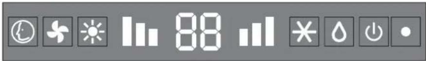
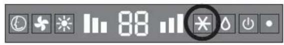
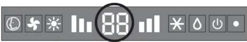
| Led Function | ||
| ® | SMART SMART | mode |
| + | FAN Fan mode | |
| * | HEAT HEAT mode | |
| III | FAN SPEED | High fan speed Medium fan speed Low fan speed |
| Led Function | ||
| 88 | DISPLAY (temp) | Indicates the temperature in °C |
| × | COOL COOL mode | |
| △ | DRY Dry mode | |
| ◎ | RUN Indicates switching on of the appliance | |
| ● | ON (led) Shows that the unit is powered | |

The shape and position of switches and indicators may vary according to the model, but their function is the same.

Danger of electric shock with open grille.

If the remote control is lost, proceed as follows:
-
If the unit is turned off, press the Automatic restart button on the unit to start the air conditioner in the SMART mode. The air conditioner will automatically choose the cooling, dehumidifying or heating mode according to environmental conditions to ensure maximum comfort.
-
To turn off the unit, press the Automatic restart button again.
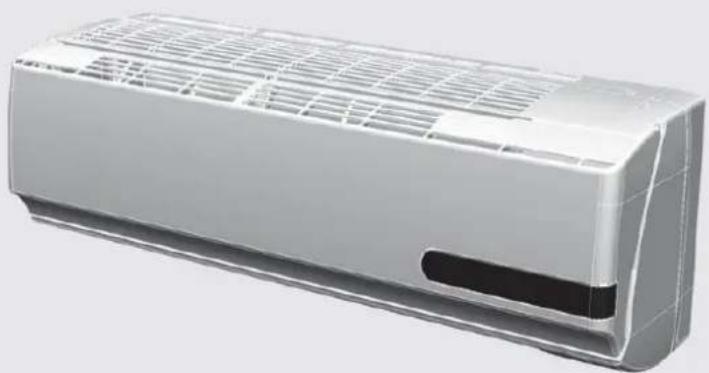
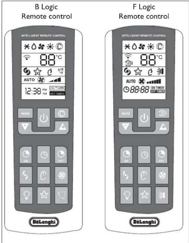
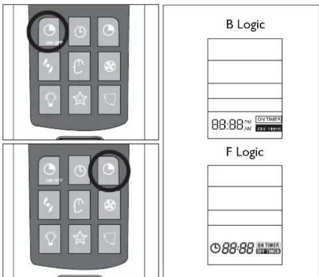
REMOTE CONTROL
USER
| No. | Button | Function |
| MODE | MODE Selection of | mode of operation |
| ON/OFF | ON/Off | On/Off |
| TEMP DN | Decrease of temperature or time by 1 unit | |
| TEMP UP | Increase of temperature or time by 1 unit | |
| T-ON | To set automatic switching-on | |
| CLOCK | To set the clock | |
| T-OFF | To set automatic switching-off | |
| TURBO POWER | TURBO function | |
| I COMFORT | I COMFORT mode | |
| FAN | Selection of fan speed | |
| LIGHT | To illuminate/darken ECC display LED of indoor unit | |
| SLEEP | Night function | |
| SWING | To adjust the position of the flaps | |
| SMART(*) | Automatic operation | |
| ROOM TEMPERATURE(**) | Temperature display mode | |
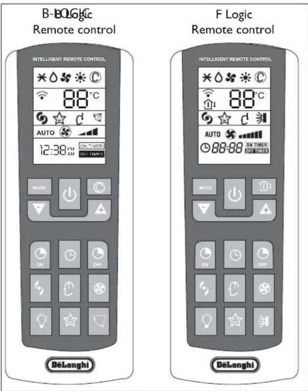
() Only on B Logic remote control
() Only on F Logic remote control
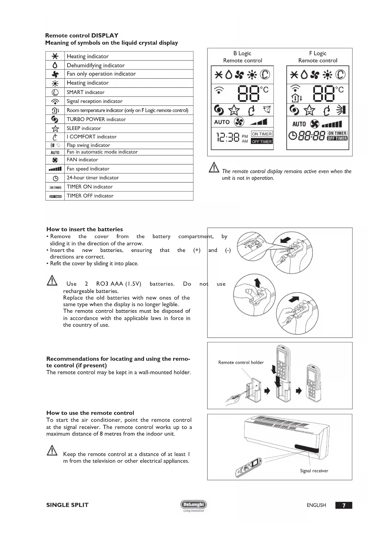
Remote control DISPLAY
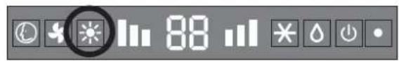
Meaning of symbols on the liquid crystal display
| * | Heating indicator |
| △ | Dehumidifying indicator |
| * | Fan only operation indicator |
| ※ | Heating indicator |
| ◎ | SMART indicator |
| ◎ | Signal reception indicator |
| ◎ | Room temperature indicator (only on F Logic remote control) |
| ◎ | TURBO POWER indicator |
| ☆ | SLEEP indicator |
| △ | I COMFORT indicator |
| ¶ | Flap swing indicator |
| AUTO | Fan in automatic mode indicator |
| § | FAN indicator |
| …………… | Fan speed indicator |
| ◎ | 24-hour timer indicator |
| [ON TIMER] | TIMER ON indicator |
| OFF TICKED | TIMER OFF indicator |
| B Logic Remote control | F Logic Remote control | ||
| ×△SS | ○ | ×△SS | ○ |
| 88°C | 88°C | ||
| ☆ | ☆ | ||
| AUTO | AUTO | ||
| 12:38 PM AM | ON TIMER OFF TIMER | 188:88 | ON TIMER OFF TIMER |

The remote control display remains active even when the unit is not in operation.
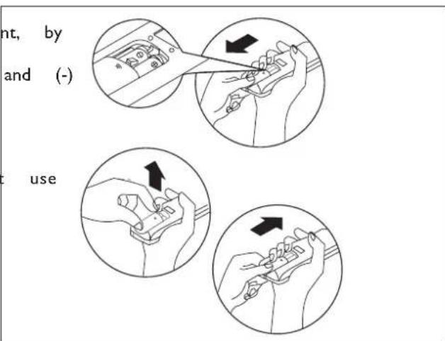
How to insert the batteries
- Remove the cover from the battery compartment sliding it in the direction of the arrow.
- Insert the new batteries, ensuring that the (+) directions are correct.
- Refit the cover by sliding it into place.

Use 2 RO3 AAA (1.5V) batteries. Do not rechargeable batteries.
Replace the old batteries with new ones of the same type when the display is no longer legible.
The remote control batteries must be disposed of in accordance with the applicable laws in force in the country of use.
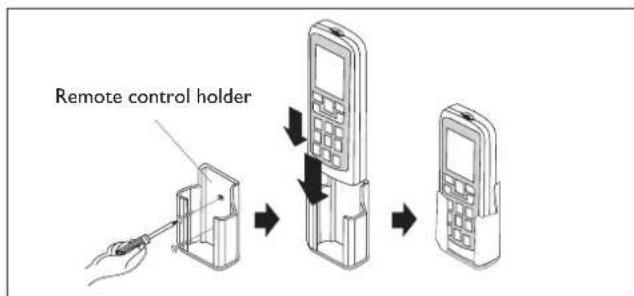
Recommendations for locating and using the remote control (if present)
The remote control may be kept in a wall-mounted holder.
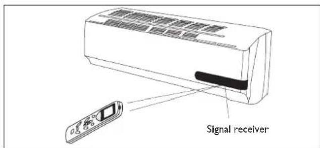
How to use the remote control
To start the air conditioner, point the remote control at the signal receiver. The remote control works up to a maximum distance of 8 metres from the indoor unit.

Keep the remote control at a distance of at least 1 m from the television or other electrical appliances.
| Mode of operation | |
| ON/OFF | On/Off/Stand-by. The symbol ∅ appears on the remote control display when the conditioner is switched on |
| FAN (Fan Mode) | Every time the FAN button is pressed the speed changes in the following sequence: AUTO - LOW - MEDIUM - HIGH. If you select the AUTO FAN speed, the electronic control chooses the fan speed automatically. In AUTO mode, the electronic control chooses the operating mode(COOLING or HERATING) and the fan speed. |
| SWING | Adjustment of airflow. Press the "SWING" button to start the automatic swing of the airflow direction flaps; press the "SWING" button again to stop the movement. If the appliance is operating in the HEAT mode when the "SWING" button is pressed, the start of this function will be deliberately delayed for a few seconds to ensure the immediate outflow of warm air for user comfort (Hot-Start function). |
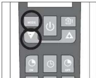
| MODE (F Logic) | Mode of operation selection. Every time the MODE button is pressed the mode of operation changes in the following sequence: COOLING - DRY - FAN - HEATING - SMART. Note: on the B Logic remote control the sequence is: COOLING - DRY - FAN - HEATING |
| SMART (B Logic) | Activation of the automatic mode of operation (SMART) |
| TEMP DN/UP | Setting of temperature. Press once to raise (+C°) or lower (-C°) the set to by 1°C. Available range of temperature settings: HEATING 16°C ~ 30°C COOLING 16°C ~ 30°C DEHUMIDIFYNG 16°C ~ 30°C FAN 16°C ~ 30°C |
Note: the appliance will start in the mode of operation that was selected before switching off.

Do not turn the vertical airflow direction flaps by hand, since this could cause malfunctioning. In the case of flap malfunction, first of all switch off the appliance, disconnect it from the power supply and then reconnect it.
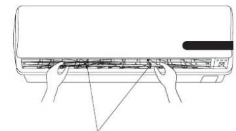
Adjustment of horizontal airflow (manual)
To change the angle of the airflow, turn the adjusting cursors of the horizontal airflow direction flaps as shown.
Note: the unit shown here may be different from the air conditioner you have purchased.

This adjustment must be done with the appliance switched off.
Note: the appliance will start in the mode of operation that was selected before switching off.
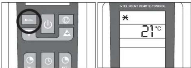
COOLING MODE
USER
The cooling function allows the air conditioner to be started and used as a producer of cool air.
To activate the cooling function (COOL), press the MODE button until the symbol () appears on the display. To change the temperature value, use the (TEMP UP and TEMP DN). buttons. Each time the buttons are pressed the set temperature value increases or decreases by 1^
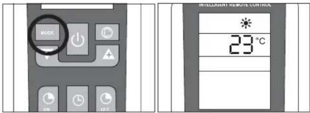
HEATING MODE
USER
The heating function allows the air conditioner to be started and used as a producer of hot air.
To activate the heating function (HEAT), press the MODE button until the symbol () appears on the display. To change the temperature value, use the (TEMP UP e TEMP DN). buttons. Each time the buttons are pressed the set temperature value increases or decreases by 1^
The appliance is fitted with a Hot Start function, which delays appliance start-up for a few seconds to ensure an immediate output of hot air.
TIMER MODE
USER

Before setting the timer, ensure that the time on the remote control is set correctly. If it is not, consult the instructions given on page 6.
Automatic switching-on
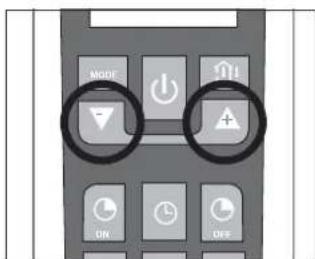
To set the automatic switching-on of the air conditioner, proceed as follows:
- With the appliance switched off, press the button TIMER ON (ON).
- Set the automatic switching-on time using the and button.
- Press the TIMER ON button within 5 seconds to confirm otherwise the function will exit from time setting.
Note: to cancel the function setting, press the TIMER ON button again.
Automatic switching-off
To set the automatic switching-off time, proceed as follows:
- Press the TIMER OFF ( ) button.
- Set the automatic switching-off time using the and button.
- Press the TIMER OFF button within 5 seconds to confirm, otherwise the function will exit from time setting.
Note: to cancel the function setting, press the TIMER OFF button again.
Note: it is also possible to set the appliance switching-on and switching-off time so as to define a specific duration of operation.
Note: the appliance will start in the mode of operation that was selected before switching off.
FAN MODE
USER
Fan mode
Press the MODE button until the FAN () symbol appears. Every time the FAN button is pressed the speed changes in the following sequence: AUTO - LOW - MEDIUM - HIGH. The remote control also stores the speed that was set in the previous mode of operation.
In SMART mode the air conditioner automatically chooses the fan speed and the mode of operation (COOLING or HEATING).
Note:
Once the fan speed has been set the indicator lights will start to blink from the lowest to the tallest at a speed that varies according to the set fan speed.
See the table to the side for an example.
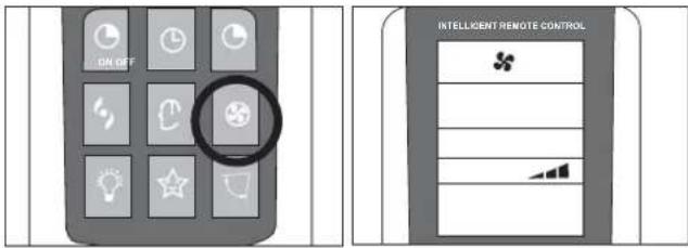
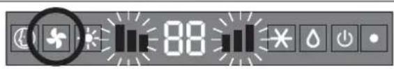
| Indoor unit display |
| Blinking Set speed |
| Slow Minimum fan speed |
| Medium Medium fan speed |
| Fast Maximum fan speed |
DRY MODE
USER
Dehumidifying mode
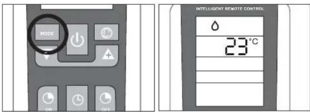
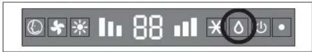
Press the MODE button until the DRY symbol () appears.
The appliance activates according to the room and the set temperature:
If the room temperature is 2^ lower than the set temperature, the compressor and the outdoor unit stop while the indoor unit fan operates at low speed.
If the room temperature is 2^ higher than the set temperature, the appliance automatically passes to the dehumidifying function, activating the fan at low speed.
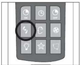
SMART MODE
USER
Modalità automatica
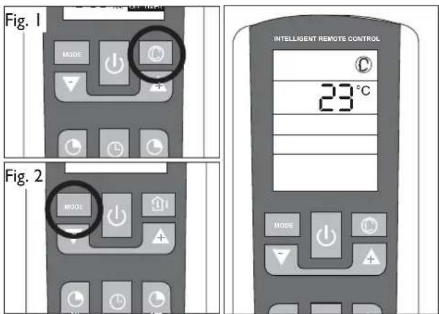
B Logic Remote Control (Fig. 1): To activate the SMART function, press the SMART button () on the remote control. The writing SMART will appear on the remote control display.
F Logic Remote Control (Fig. 2):
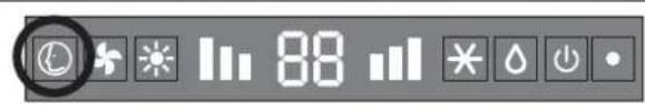
To activate the SMART (automatic) mode of operation press the MODE button on the remote control until the symbol appears on the display.
In the AUTO mode the fan speed and the temperature are set automatically according to the room temperature to ensure user comfort.
| Room temperature Modr | |
| between 22°C HEATING | |
| 22 ~ 24°C DRY | |
| above 26°C COOLING | |
Note: after having stopped the SMART function, the air conditioner will start up with the settings of the previously selected modes.
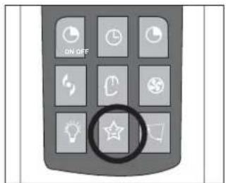
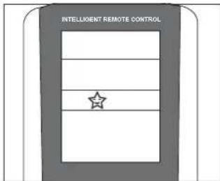
SLEEP MODE
USER
Night mode
To activate the night function in the COOL, DRY and HEAT modes, press the SLEEP button. The symbol☆ appears on the display. To deactivate the night function, press the SLEEP (☆) button again.
During operation in the night mode, the set temperature increases by 1^ in the first hour of operation and by another 1^ in the following hour, maintaining this increase of 2^ in the subsequent hours.
Selecting the night function in the heating mode, the set temperature decreases by 1^ in the first hour of operation and by another 1^ in the following hour, maintaining this decrease of 2^ in the subsequent hours with the fan operating at minimum speed.
NOTE: Under FAN and SMART modes, this function is not available.
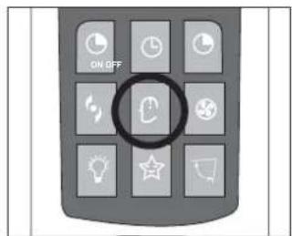
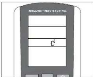
I COMFORT FUNCTION
USER
Press the I COMFORT (t), button and the symbol appears on the display.
This function is used to obtain the required climate in the exact point where the remote control is located.
The temperature of reference is that measured by the sensor in the remote control, bypassing the temperature sensor inside the air conditioner.

The remote control must always by pointed at the unit.

If no signal is received from the remote control for 11 minutes, the unit will once again refer to its own internal sensor
ROOM TEMPERATURE FUNCTION
USER
Press the ROOM TEMPERATURE button (only on the F Logic remote control) for the various modes of measuring the temperature in the room where the appliance is installed.
A few display examples are given in the table:
| I-COMFORT function not active | ||
| Remote control display Indoor or unit display | ||
| Set temperature Set | temperature | |
| Temp. measured by indoor unit sensor | Set temperature | |
| Function unavailable | ||
| I-COMFORT function active | ||
| Temp. measured by remote control sensor | Set temperature | |
TURBO POWER FUNCTION
USER
To activate the TURBO POWER function, press the button. The symbol appears on the display.
In the COOL or HEAT mode, the air conditioner will automatically operate at maximum power. To deactivate this function just change the fan speed or press the button again.
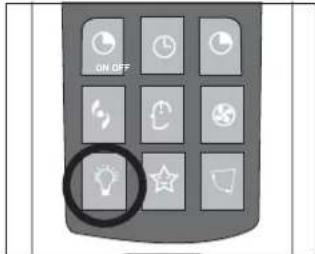
LIGHT FUNCTION
USER
Press the LIGHT ( ) Upon activating this function the LEDs on the indoor unit display go out while air conditioner operation remains unchanged. This function is useful at night when the display lights could be bothersome.
ANOTHER FUNCTIONS
USER
LOCK function (if present)
Press and buttons simultaneously to lock or unlock the keyboard. If the remote controller is locked, press any button, the remote control can't work, you must unlock the keyboard.
Switch between Centigrade and Fahrenheit (if present)
Under status unit off, press MODE and buttons simultaneously to switch ^ C and ^ F .
HANDLING
USER

Carefully remove the adhesive strips from the appliance

After having removed the packaging, check that the contents are intact and complete.

The outdoor unit must always be kept upright.

Handling must be done by suitably equipped qualified technical personnel using equipment that is suitable for the weight of the appliance.
INSTALLING THE INDOOR UNIT
USER
Before starting installation, decide on the position of the indoor and outdoor units, taking into account the minimum clearance required around the units (see technical data table).

Install the indoor unit in the room to be air conditioned, avoiding installations in corridors or communal areas.

Install the indoor unit at a height of at least 2.5m from the ground.
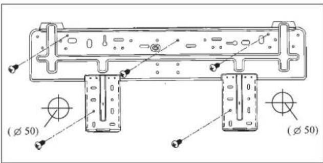
To install, proceed as follows: Installation of the mounting
- Drill 32mm deep holes in the wall for fixing the plate;
- insert the plastic anchors into the hole;
- fix the mounting plate using the self-tapping screws provided;
- check that the mounting plate is correctly fixed;
- using a spirit level, check that it is level.
Drilling a hole in the wall for the piping
- Decide where to drill the hole in the wall for the piping (if necessary) according to the position of the mounting plate;
- install a flexible flange through the hole in the wall to keep the latter intact and clean.

The hole must slope downwards towards the exterior.
Installing the refrigerant, electrical and condensate drainage pipes
Pass the pipe (for liquids and gas) through the hole in the wall from the exterior or install it from the indoor side, after having laid the pipes and connected the cables to the indoor unit, ready for connection to the outdoor unit.
Decide whether or not to remove the knockout according to the direction of the piping.
Water connections

Before installing the air conditioner, choose the direction for the pipes to exit; they may be arranged along any one of the 4 directions shown in the figure:
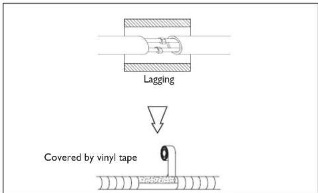
After having connected the pipe according to the instructions, install the drain hose. Now install the power cables. After connection, lag the pipe, cables and drain hose with the insulating material.

Lag the pipe joints with insulating material, securing it with vinyl tape.

Cover the through holes in the wall with elastic material that is also noise absorbing if possible.

Upon completion of installation, check that the condensate flows out regularly.
Lagging the pipes

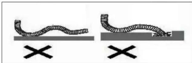
Place the drain hose (not provided in the kit) below the piping, taking care not to create siphons.

Use polythene foam with thickness exceeding 6 mm to insulate the connections.

The drain hose must slant downwards to aid drainage.

Do not bend the drain hose or leave it protruding or twisted and do not put the end of it in water. If an extension is connected to the drain hose, ensure that it is lagged when it passes into the indoor unit.

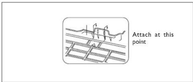
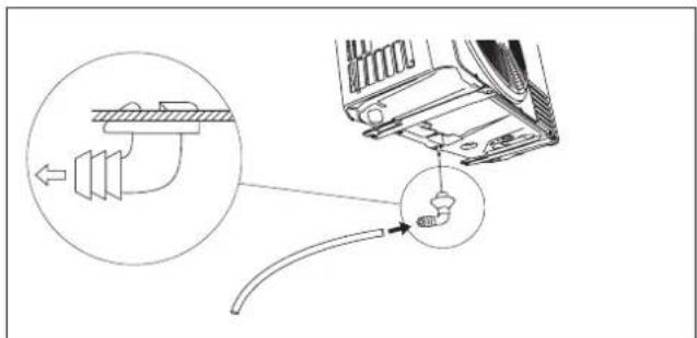
If the piping is installed to the right, the pipes, power cable and drain hose must be lagged and secured onto the rear of the unit with a pipe connection.
I. Insert the pipe connection into the relative slot.
2. Press to join the pipe connection to the base.
Connecting the pipes
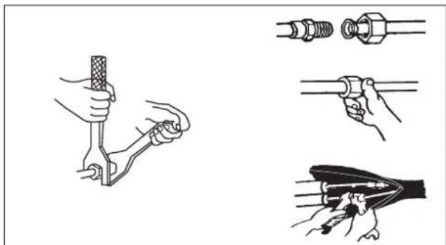
Use two wrenches to tighten the indoor unit pipe joints.

Pay particular attention to the torque recommended below in order not to risk deforming and damaging flared pipes, connectors and nuts.

Tighten the connections using two wrenches working in opposite directions (see technical data table).
Electrical connections
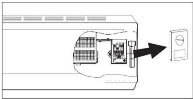
The terminal blocks on the units must be accessed to carry out the electrical connections.
See the pictures at the side.

To ensure correct size of the wires for the electrical connection and for connecting the units together, see the technical data table.

For the electrical connections, see the circuit diagram inside the access flap and refer to the information given in this manual.

The cable connecting the outdoor and indoor units must be suitable for outdoor use.

The plug must be accessible also after the appliance has been installed so that it can be pulled out if necessary.

Installation of an omnipolar thermomagnetic line-disconnecting switch to CEI-EN standards (with contact separation of at least 3mm ) near the appliance is compulsory.

An efficient earth connection must be ensured.

If the power cable is damaged, it must be replaced by an authorised Service Centre.

Under no circumstances should gas or water pipes be used for earthing the appliance.

Upon completion of connections, secure the cables with cable glands and replace the terminal block covers.

Failure to comply with these instructions and accident-prevention regulations relieves the manufacturer from all liability.
WIRING DIAGRAMS FOR
CONVERTER
MODELS
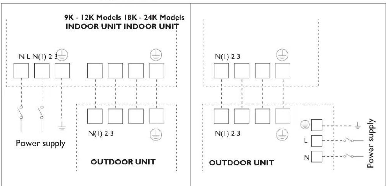
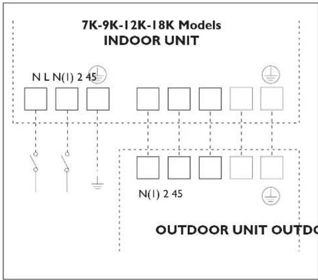
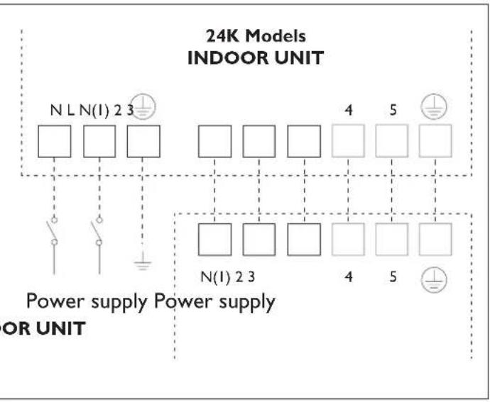

Ensure that when connecting the indoor and outdoor units, the numbering on the respective terminal blocks is observed.

We suggest the installation of RCD device with nominal differential current that doesn't exceed the 30mA
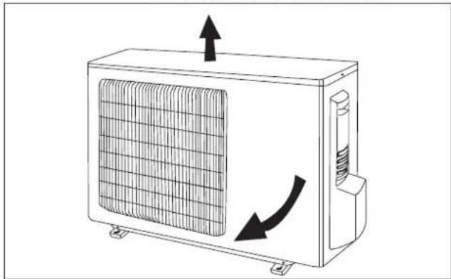
INSTALLING THE OUTDOOR UNIT
INSTALLER
Location

Use bolts to secure the unit to a flat, solid floor. When mounting the unit on a wall or the roof, make sure the support is firmly secured so that it cannot move in the event of intense vibrations or a strong wind.

Do not install the outdoor unit in pits or air vents
Installing the pipes

Use suitable connecting pipes and equipment for the refrigerant in the appliance (see rating plate).

The refrigerant pipes must not exceed the maximum lengths given in the technical data table.

Lag all the refrigerant pipes and joints.

Tighten the connections using two wrenches working in opposite directions.
Install the drain fitting and the drain hose (for model with heat pump only)
Condensation is produced and flows from the outdoor unit when the appliance is operating in the heating mode. In order not to disturb neighbours and to respect the environment, install a drain fitting and a drain hose to channel the condensate water. Install the drain fitting and rubber washer on the outdoor unit chassis and connect a drain hose to it as shown in the figure.

Do not install the outdoor unit where it is exposed to sunlight.

Ensure that the recommended space is left around the appliance.
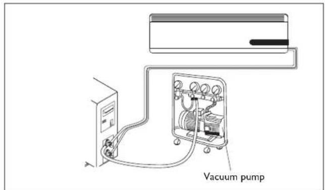
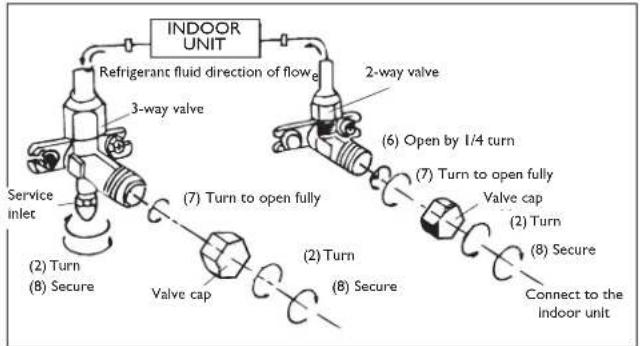
Humid air left inside the refrigerant circuit can cause compressor malfunction. After having connected the indoor and outdoor units, bleed the air and humidity from the refrigerant circuit using a vacuum pump.
(1) Unscrew and remove the caps from the 2-way and 3-way valves.
(2) Unscrew and remove the cap from the service valve.
(3) Connect the vacuum pump hose to the service valve.
(4) Operate the vacuum pump for 10-15 minutes until an absolute vacuum of 10mmHg has been reached.
(5) With the vacuum pump still in operation, close the low-pressure knob on the vacuum pump coupling. Stop the vacuum pump.
(6) Open the 2-way valve by 1/4 turn and then close it after 10 seconds. Check all the joints for leaks using liquid soap or an electronic leak device.
(7) Turn the body of the 2-way and 3-way valves. Disconnect the vacuum pump hose.
(8) Replace and tighten all the caps on the valves.
MAINTENANCE
INSTALLER

Periodic maintenance is essential for keeping your air conditioner efficient.

Before carrying out any maintenance, disconnect from the power supply by putting the installation on/off switch to "off".
INDOOR UNIT
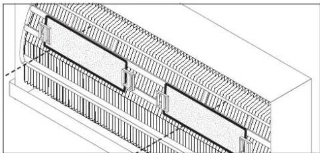
Removing and cleaning the filter
- Open the front panel following the direction of the arrow (1)
- Keeping the front panel raised with one hand, take out the air filter with the other hand
- Clean the filter with water; if the filter is soiled with oil, it can be washed with warm water (not exceeding 45^ ). Leave to dry in a cool and dry place.
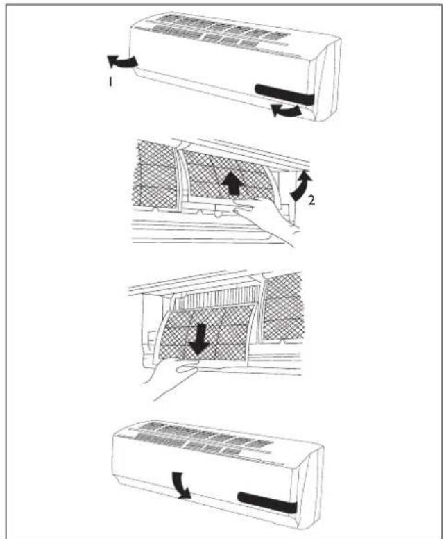
Installing the fi Iter
- Keeping the front panel raised with one hand, insert the air filter with the other hand (see fi g.)
Insert the air filter
Close

The active carbons electrostatic fi lter (if installed) cannot be washed or regenerated. It must be replaced with new fi lter once every 6 months.
OUTDOOR UNIT

Use suitable instruments for the refrigerant in the appliance.

Only use the refrigerant indicated on the rating plate.

Do not use mineral oils to clean the unit.
Note: the above figures may not correspond to the appearance of the units that have been purchased.
POSSIBLE ERRORS
INSTALLER
| Error code for modeler | |
| Code | Error |
| E1 | High pressure protection |
| E2 | Defrost protection |
| E3 | Low pressure protection |
| E4 | Compressor gas discharge protection |
| E5 | Current overload protection |
| E6 | Communication malfunction |
| E7 | MODE conflict |
| E8 | High temperature protection |
| E9 | Protection against cold air |
| F1 | Indoor unit room sensor disconnected |
| F2 | Indoor unit pipe sensor disconnected |
| F3 | Outdoor unit ambient sensor disconnected |
| F4 | Outdoor unit pipe sensor disconnected |
| F5 | Outdoor unit delivery line sensor short-circuited/disconnected |
| H5 | No feedback from indoor motor |
| C2 | Current leakage protection |
| C3 | Wrong connection protection |
| C6 | No earthing |
| C5 | Jumper error protection |
| F7 | Oil circle under cooling mode |
| F8 | Current overload cause frequency decreased |
| F9 | Exhaust overload cause frequency decreased |
| F0 | Sistem fl uorin lack or jam protection |
| H1 | Defrosting |
| H2 | Static dust eliminated protection |
| H3 | Compressor overload protection |
| H4 | System abnormality |
| H5 | IPM Module protection |
| Code | Error |
| HC | PFC protection |
| H7 | Synchronization failure |
| HB | Full of water protection |
| HS | Heater error |
| HQ | High temperature(heat mode) cause frequency decreased |
| FR | Tube temperature overload cause frequency decreased |
| FH | Freezing cause frequency decreased |
| Error code for ON-OFF 7-9-12K models | |
| Code | Error |
| HI | Defrosting |
| H6 | No feedback from indoor motor |
| CS | Jumper error protection |
| Error code for SON-OFF 18-24K models | |
| Code | Error |
| ES | Current overload protection |
| CS | Jumper error protection |
| F1 | Indoor unit room sensor disconnected |
| F2 | Indoor unit pipe sensor disconnected |
| HS | No feedback from indoor motor |
| HI | Defrosting |
| Malfunction Possible causes | |
| ·The appliance does not operate | Power failure/Plug pulled out |
| Damaged indoor/outdoor unit fan motor | |
| Faulty compressor thermomagnetic circuit breaker | |
| Faulty protective device or fuses. | |
| Loose connections or plug pulled out | |
| It sometimes stops operating to protect the appliance. | |
| Voltage higher than 244V or lower than 206V | |
| Active TIMER-ON function | |
| Damaged electronic control board | |
| ·Strange odour Dirty air filter | |
| ·Noise of running water Back flow of liquid | in the refrigerant circuit |
| ·A fine mist comes from the air outlet | This occurs when the air in the room becomes very cold, for example in the "COOLING" or "DEHUMIDIFYING/DRY" modes. |
| ·A strange noise can be heard | This noise is made by the expansion or contraction of the front panel due to variations in temperature and does not indicate a problem. |
| ·Insufficient airflow, either hot or cold | Unsuitable temperature setting. |
| Obstructed air conditioner intakes and outlets. | |
| Dirty air filter. | |
| Fan speed set at minimum. | |
| Other sources of heat in the room. | |
| No refrigerant. | |
| ·The appliance does not respond to commands | Remote control not near enough to indoor unit. |
| The remote control batteries are dead. | |
| Obstacles between remote control and signal receiver on indoor unit. | |
| ·The control panel display is off | Active LIGHT function |
| Power failure | |
| Faulty control panel | |
| Faulty electronic control board | |
| ·Switch off the air conditioner immediately and cut off the power supply in the event of: | Strange noises during operation. |
| Faulty fuses or switches. | |
| Spraying water or objects inside the appliance. | |
| Overheated cables or plugs. | |
| Very strong smells coming from the appliance. | |
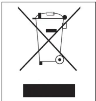
RECOMMENDATIONS FOR CORRECT DISPOSAL OF THE PRODUCT PURSUANT TO EUROPEAN DIRECTIVE 2002/96/EC
At the end of its useful life the product must not be disposed of together with municipal waste.
It may be taken to special centres for separately collected fractions set up by municipal authorities or to dealers that provide this service.
By disposing of a household electrical appliance separately, it is possible to avoid potential negative consequences for the environment and for health due to unsuitable disposal. It also allows the component materials to be recovered with consequent important saving of energy and resources.
To show the obligation to dispose of the household electrical appliances separately, the product bears the symbol of the crossed-out wheeled bin.
ENVIRONMENTAL INFORMATION
INSTALLER
This unit contains fluorinated gases with greenhouse effect covered by the Kyoto Protocol. Maintenance and disposal must be carried out by qualified persons only.
Refrigerant gas R410A, GWP=1975.
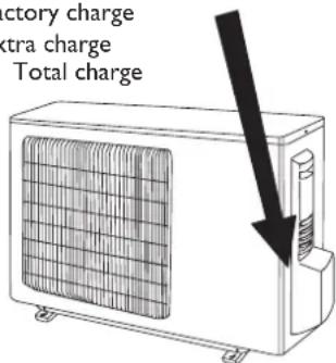
EXTRA REFRIGERANT CHARGE
INSTALLER
Pursuant to Regulation (EC) 842/2006 on certain fluorinated greenhouse gases, in case of extra refrigerant charge, it is compulsory to:
- Fill in the label accompanying the unit inserting the factory quantity of refrigerant charge (see the technical label), the extra refrigerant charge and the totalk charge.
- apply the label next to the technical label applied on the outdoor unit;

Use an indelible pen.
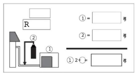
Factory charge
2 Extra charge
1+2 Total charge
USEFUL INFORMATION
For information on servicing and spare parts, please contact:
UFFICIO ASSISTENZA TECHNICA GRUPPO DE'LONGHI
Via L. Seitz, 47 - 31100 Treviso (ITALY)
In line with the company's policy of continual product improvement, the aesthetic and dimensional characteristics, technical data and accessories of this appliance may be changed without notice.
Chere CLIENT, Cher Client
Mode Deshumidification
Raccordements hydrauliques

We suggest the installation of RCD device with nominal differential current that doesn't exceed the 30mA .
INSTALLATION DE L'UNITE EXTERNE
INSTALLATEUR
Positionnement

Pursuant to Regulation (EC) 842/2006 on certain fluorinated greenhouse gases, in case of extra refrigerant charge, it is compulsory to:
- Fill in the label accompanying the unit inserting the factory quantity of refrigerant charge (see the technical label), the extra refrigerant charge and the totalk charge.
- apply the label next to the technical label applied on the outdoor unit;

We suggest the installation of RCD device with nominal differential current that doesn't exceed the 30mA .
INSTALLATION DES AUSSENGERATS
INSTALLATEUR
Positionierung

Pursuant to Regulation (EC) 842/2006 on certain fluorinated greenhouse gases, in case of extra refrigerant charge, it is compulsory to:
- Fill in the label accompanying the unit inserting the factory quantity of refrigerant charge (see the technical label), the extra refrigerant charge and the totalk charge.
- apply the label next to the technical label applied on the outdoor unit;

We suggest the installation of RCD device with nominal differential current that doesn't exceed the 30mA .
Pursuant to Regulation (EC) 842/2006 on certain fluorinated greenhouse gases, in case of extra refrigerant charge, it is compulsory to:
- Fill in the label accompanying the unit inserting the factory quantity of refrigerant charge (see the technical label), the extra refrigerant charge and the totalk charge.
- apply the label next to the technical label applied on the outdoor unit;

Como colocar as pilhas
We suggest the installation of RCD device with nominal differential current that doesn't exceed the 30mA .
INSTALACAO DA UNIDADE EXTERIOR
INSTALADOR
Posicionamento


- OPERATING AND INSTALLATION MANUAL
- ONEinverter
- CONTENTS
- GENERAL INFORMATION
- GENERAL INFORMATION Page.
- USER Page.
- INSTALLER Page.
- CONFORMITY AND RANGE
- SAFETY RULES AND RECOMMENDATIONS FOR THE USER
- NAMES OF THE PARTS
- INDOOR UNIT
- No. Description
- OUTDOOR UNIT
- REMOTE CONTROL
- USER
- Remote control DISPLAY
- Meaning of symbols on the liquid crystal display
- How to insert the batteries
- Recommendations for locating and using the remote control (if present)
- How to use the remote control
- Adjustment of horizontal airflow (manual)
- COOLING MODE
- HEATING MODE
- TIMER MODE
- Automatic switching-on
- Automatic switching-off
- FAN MODE
- Note:
- DRY MODE
- Dehumidifying mode
- SMART MODE
- Modalità automatica
- SLEEP MODE
- Night mode
- I COMFORT FUNCTION
- ROOM TEMPERATURE FUNCTION
- TURBO POWER FUNCTION
- LIGHT FUNCTION
- ANOTHER FUNCTIONS
- LOCK function (if present)
- Switch between Centigrade and Fahrenheit (if present)
- HANDLING
- INSTALLING THE INDOOR UNIT
- Drilling a hole in the wall for the piping
- Installing the refrigerant, electrical and condensate drainage pipes
- Water connections
- Lagging the pipes
- Connecting the pipes
- Electrical connections
- WIRING DIAGRAMS FOR
- CONVERTER
- MODELS
- INSTALLING THE OUTDOOR UNIT
- INSTALLER
- Location
- Installing the pipes
- Install the drain fitting and the drain hose (for model with heat pump only)
- MAINTENANCE
- Removing and cleaning the filter
- Installing the fi Iter
- POSSIBLE ERRORS
- RECOMMENDATIONS FOR CORRECT DISPOSAL OF THE PRODUCT PURSUANT TO EUROPEAN DIRECTIVE 2002/96/EC
- ENVIRONMENTAL INFORMATION
- EXTRA REFRIGERANT CHARGE
- USEFUL INFORMATION
- UFFICIO ASSISTENZA TECHNICA GRUPPO DE'LONGHI
- Mode Deshumidification
- Raccordements hydrauliques
- INSTALLATION DE L'UNITE EXTERNE
- INSTALLATEUR
- Positionnement
- INSTALLATION DES AUSSENGERATS
- Positionierung
- Como colocar as pilhas
- INSTALACAO DA UNIDADE EXTERIOR
- INSTALADOR
- Posicionamento
Brand : DELONGHI
Model : One 140
Category : Air Conditioning