
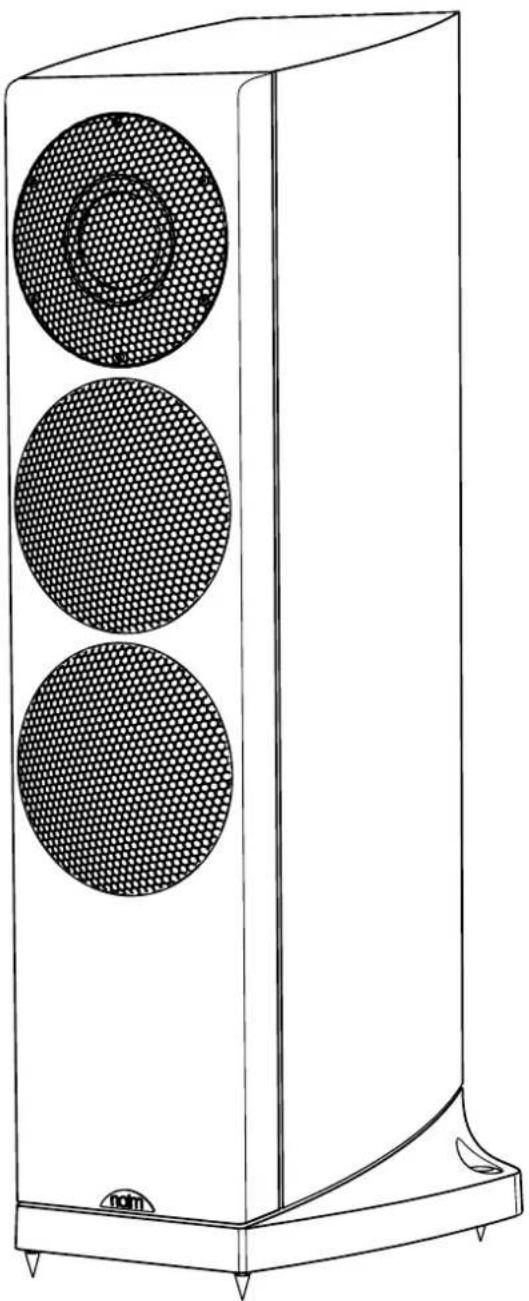
Ovator S400 - Speaker NAIM - Free user manual and instructions
Find the device manual for free Ovator S400 NAIM in PDF.
| Product type | Floorstanding loudspeaker |
| Brand | Naim |
| Model | Ovator S400 |
| Category | Loudspeaker |
| Frequency response | 36 Hz - 35 kHz (in-room) |
| Sensitivity | 88 dB @ 1m for 2.83 V |
| Recommended amplifier power | 25 - 130 W (8 Ohms) |
| Weight | 31 kg (spikes and grilles included) |
| Filter type | Passive filter (convertible to active) |
| Connections | Binding posts accepting special Ovator connector |
| Recommended cable length | 3.5 to 20 metres |
| Decoupling | Adjustable decoupling spikes |
| Safety standards | EN 60065 |
| Electromagnetic compatibility | EN 55013, EN 55020 |
Frequently Asked Questions - Ovator S400 NAIM
User questions about Ovator S400 NAIM
0 question about this device. Answer the ones you know or ask your own.
Ask a new question about this device
Download the instructions for your Speaker in PDF format for free! Find your manual Ovator S400 - NAIM and take your electronic device back in hand. On this page are published all the documents necessary for the use of your device. Ovator S400 by NAIM.
USER MANUAL Ovator S400 NAIM
OVATOR S-600 & S-400 - English
Introduction and Unpacking
The Ovator S-600 and S-400 are very high performance speakers that will repay effort spent on installation. It is important that you read this manual before fully unpacking and installing your Ovators. The manual begins with unpacking instructions. Ovators are extremely heavy and to minimise the risk of damage or personal injury you should follow these instructions carefully. Unpacking and installing Ovators is a two-person task and should not be attempted alone.
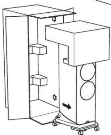
1 S-600 Unpacking
It is important that Ovators are unpacked as described in the following paragraphs and illustrations.
They should be unpacked in the room in which they are to be used and close to their likely installed positions.
Having removed this manual proceed to unpack each Ovator following the steps below:
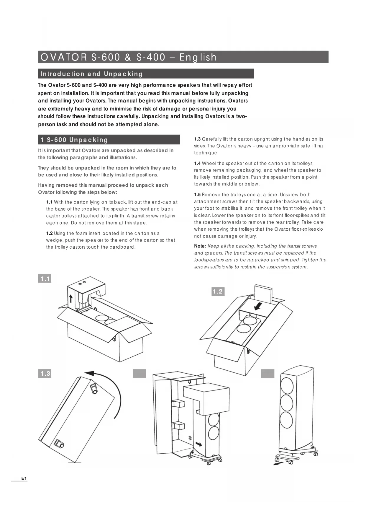
1.1 With the carton lying on its back, lift out the end-cap at the base of the speaker. The speaker has front and back castor trolleys attached to its plinth. A transit screw retains each one. Do not remove them at this stage.
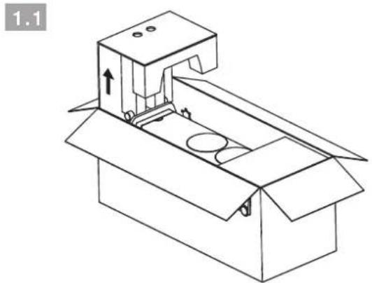
1.2 Using the foam insert located in the carton as a wedge, push the speaker to the end of the carton so that the trolley castors touch the cardboard.
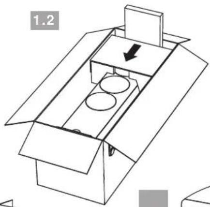
1.3 Carefully lift the carton upright using the handles on its sides. The Ovator is heavy - use an appropriate safe lifting technique.
1.4 Wheel the speaker out of the carton on its trolleys, remove remaining packaging, and wheel the speaker to its likely installed position. Push the speaker from a point towards the middle or below.
1.5 Remove the trolleys one at a time. Unscrew both attachment screws then tilt the speaker backwards, using your foot to stabilise it, and remove the front trolley when it is clear. Lower the speaker on to its front floor-spikes and tilt the speaker forwards to remove the rear trolley. Take care when removing the trolleys that the Ovator floor-spikes do not cause damage or injury.
Note: Keep all the packing, including the transit screws and spacers. The transit screws must be replaced if the loudspeakers are to be repacked and shipped. Tighten the screws sufficiently to restrain the suspension system.
OVATOR S-600 & S-400 - English
2 S-400 Unpacking
It is important that Ovators are unpacked as described in the following paragraphs and illustrations.
They should be unpacked in the room in which they are to be used and close to their likely installed positions.
Having removed this manual proceed to unpack each Ovator following the steps below:
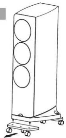
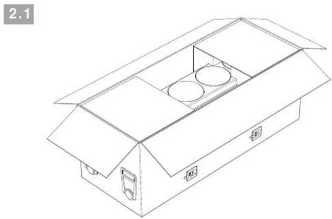
2.1 The carton should be lying on its back with the side and end flaps open.
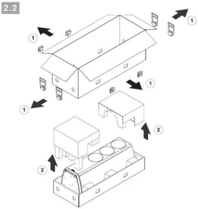
2.2 Remove the plastic side clips and handles from the carton and lift off the outer sleeve and internal packaging. The Ovator will now be left lying in its tray.
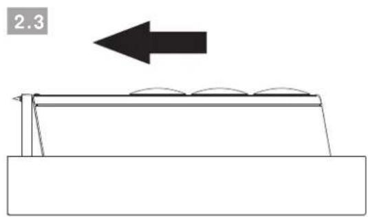
2.3 Gently push the Ovator along the tray so that its floor-spikes touch the cardboard.
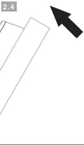
2.4 Carefully lift the tray upright. The Ovator is heavy - use an appropriate safe lifting technique. Take care not to over-balance the speaker so that it falls forwards.
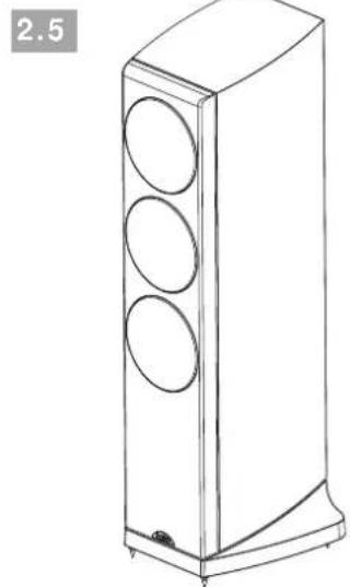
2.5 The Ovator can now be manoeuvred out of its tray and into position. Once the Ovator is in position, the plastic protection caps fitted over its floor-spikes can be removed.
Note: Keep all the packing for use if your Ovators are to be repacked and shipped.
OVATOR S-600 & S-400 - English
3 Installation
Once your Ovators are fully unpacked they may be manoeuvred into their initial working positions. Take care that the floor-spikes do not cause damage or personal injury. The S-600 incorporates BMR transit screws. These should not be removed until the speakers are installed in their final positions. The S-400 Incorporates no transit screws.
Positioning guidelines are provided in the following paragraphs but you should be prepared to make positioning adjustments as the speakers "run-in" and as you become more familiar with them.
Ovator loudspeakers are not magnetically shielded and should be kept well away from CRT displays and other magnetically sensitive items.
3.1 Positioning
The performance of any loudspeaker will be influenced by the room and position in which it is located. Even small changes of loudspeaker position can significantly influence the sound. Changes of room contents, the introduction of significant piece of furniture for example, can also have an effect.
The following paragraphs constitute only a general guide to Ovator positioning. Every listening room is different and you may find an alternative positioning solution works best in yours.
In general, try to choose a site for the speakers where they are located between 2.0 metres and 4.0 metres apart, clear of room corners, and where each one is between 0.25 metres and 1.0 metre away from a solid rear wall. The distance between the speakers and the rear wall is the aspect of positioning most likely to require adjustment as the speakers run-in and you become familiar with their performance in your room.
If the Ovator is moved closer to the rear wall the low frequency elements of music will become more prominent. However this may be at the expense of bass clarity and timing.
Note: There is no need to angle the Ovator inwards towards the listening position but doing so may be a useful fine-tuning adjustment.
The primary listening position should be central between the loudspeakers approximately the same distance away as they are apart.
Try to position each Ovator within a similar "nearfield" acoustic environment and with similar acoustic characteristics along the side walls towards the listening position.
Note: Different near-field acoustic environments and characteristics would be created by, for example, heavy curtains and glass windows, or a plasterboard wall with and without bookshelves.
Diagram 3.2 illustrates the positioning guidelines described above.
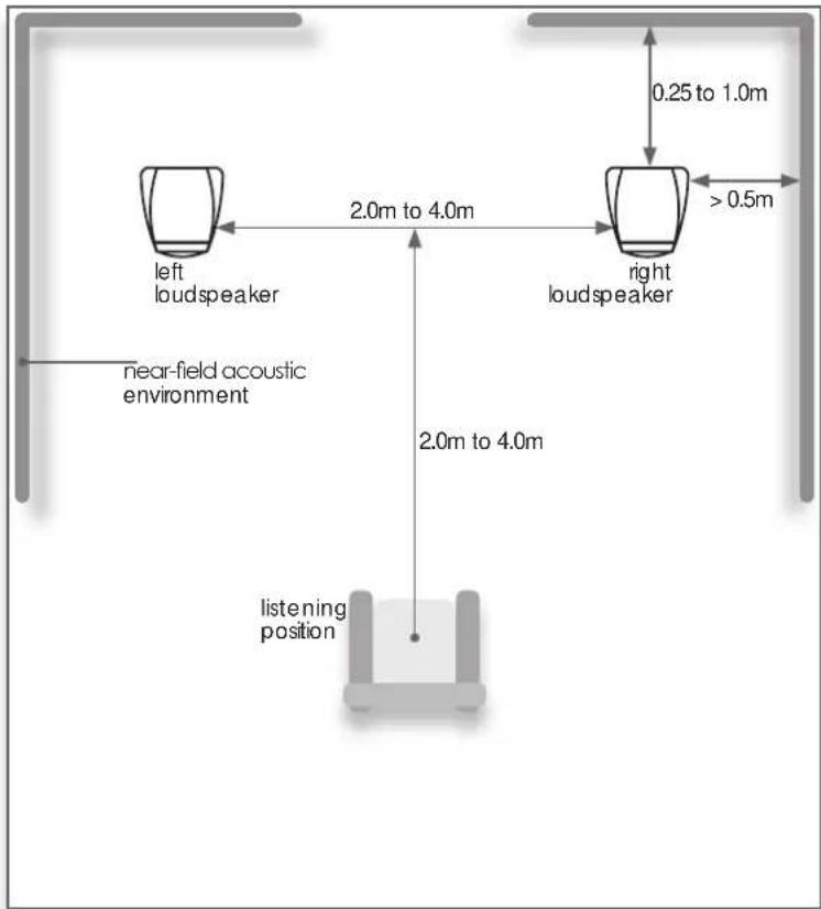
3.2 Room Layout
OVATOR S-600 & S-400 - English
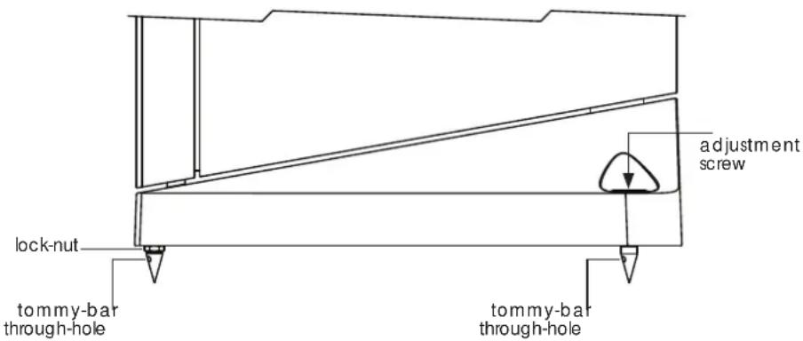
3.3 Using Floor-spikes
Ovators are fitted with floor-spikes to define the mechanical interface with the structure of the listening room. Floor-spikes should be adjusted to ensure that the speakers are upright and do not rock. Use the minimum length of floor-spike needed to hold the lock nut just above the carpet.
Note: If Ovator loudspeakers are to be installed on a non-carpeted floor, the floor-spikes should be used in conjunction with Naim Floor Protectors and adjusted so that the tip of the floor-spike extends just beyond the lock nut. Your Naim retailer or distributor will be able to supply Floor Protectors.
3.3.1 Adjusting S-600 Floor-Spikes
All four floor-spikes are adjustable, however adjustment of the S-600 rear floor-spikes is easier thanks to the top access provided by its plinth design. To adjust an S-600 rear floor-spike first remove the locking set-screw with the 4mm Allen key supplied. Then insert the Allen key from above to turn
3.4 Adjusting Floor-spikes
the adjustment screw clockwise to lengthen the floor-spike and anti-clockwise to shorten the floor-spike. If necessary, to stop the floor-spike from turning when re-tightening the locking set-screw, insert the supplied tommy-bar in the floor-spike through-hole. Diagram 3.4 illustrates S-600 rear floor-spike adjustment.
Depending on the thickness of any carpet, and prior adjustment of its rear spikes, S-600 front floor-spikes may not need any adjustment. If adjustment is required however, loosen the lock nut using a 13mm spanner and turn the floor-spike as appropriate using the supplied tommy-bar inserted in the floor-spike through-hole. Re-tighten the locknut when adjustment is complete. Diagram 3.4 illustrates front floor-spike adjustment.
3.3.2 Adjusting S-400 Floor-Spikes
To adjust an S-400 floor-spike first loosen its lock nut using a 13mm spanner. Turn the floor-spike as appropriate using the supplied tommy-bar inserted in the floor-spike through-hole. Re-tighten the lock-nut when adjustment is complete. The S-600 front floor-spike illustrated in Diagram 3.4 also illustrates S-400 floor-spikes.
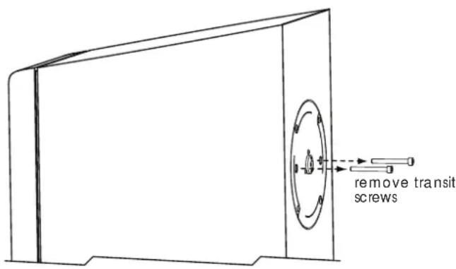
3.5 S-600 BMR Transit Screws
The Ovator S-600 BMR (balanced mode radiator) module is fitted with a twin leaf-spring suspension system. The suspension system is restrained during shipping by two transit screws that must be released before use. The transit screws are located on the rear face of the speaker directly behind the BMR.
Use the supplied 5mm Allen key to unscrew the transit screws. Remove the screws and store them safely. Diagram 3.6 illustrates removal of the transit screws.
Note: The transit screws must be replaced if the loudspeakers are to be repacked and shipped. Tighten the screws sufficiently to restrain the suspension system.
3.6 S-600 Transit Screw Removal
OVATOR S-600 & S-400 - English
4 Connecting
Ovators incorporate a passive crossover but can be converted for use in active systems using the appropriate Nalm active crossover and multiple amplifiers. Contact your local retailer or distributor for more information.
4.1 Cables and Connectors
If your Ovators are to be used with Naim amplification, Naim loudspeaker cable will produce the best results and is necessary with some amplifiers. Cable lengths to both speakers should be equal and be between 3.5 metres and 20 metres. If the position of a speaker in relation to the amplifier results in spare cable do not coil the cable but lay it out back and forth between the amplifier and speaker.
The Ovator connection terminals are intended to accept the custom-designed Ovator speaker connector. This connector is designed to provide the best possible performance. Other 4mm plugs can be used however the results will be unpredictable. Your retailer will be able to make up speaker cables terminated on one end by the Ovator connector and on the other end by a connector appropriate to the driving amplifier.
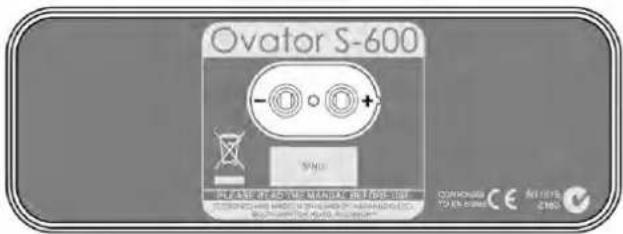
4.2 Connection Polarity
It is important that Ovators are connected with the correct polarity. Ensure that the positive terminal on each speaker (marked +) is connected to a positive output terminal on the amplifier and the negative terminal on each speaker (marked -) is connected to a negative output terminal on the amplifier. Diagram 4.3 illustrates the Ovator connection panel.
Note: Naim speaker cable has a rib running down one side to aid polarity identification. The positive side of Naim speaker plugs have a small protrusion for identification.
4.3 Ovator Connection Panel
5 Specifications
S-600 S-400
Frequency response: 28Hz - 35kHz (in room) 36Hz - 35kHz (in room)
Sensitivity: 88dB @ 1m for 2.83V input 88dB @ 1m for 2.83V input
Nominal impedance: 4 Ohms (min 3.2 Ohms) 4 Ohms (min 3.8 Ohms)
Suggested power amplifier: 25 - 150W (8 Ohm rating) 25 - 130W (8 Ohm rating)
Weight: 61 kg 31 kg
Dimensions H x W x D: 1168mm x 401mm x 434mm
1060mm x 330mm x 345mm
(inc floor-spikes and grilles) (inc floor-spikes and grilles)
6 Conformance To Appropriate Standards
Manufacturer: Naim Audio Limited, Southampton Road, Salisbury, England, SP1 2LN
Products: Ovator S-600 and S-400
Safety: EN 60065 - Audio, Video and similar electronic apparatus.
EMC Emissions: EN 55013 - Sound and television broadcast receivers and associated equipment - Radio disturbance characteristics - Limits and methods of measurements.
EMC Immunity: EN 55020 - Sound and television receivers and associated equipment - Immunity Characteristics - Limits and methods of measurement.
In accordance with 2006/95/EC - Safety, 2004/108/EC - EMC,
European Directives: 2002/95/EC (RoHS), 2002/96/EC (WEEE)
OVATOR S-600 & S-400 - Deutsch
Allgemeines
Dimensions H x L x P:
1168mm×401mm×434mm
1060mm x 330mm x 345mm
Fabricant: Naim Audio Limited, Southampton Road, Salisbury, England, SP1 2LN
Dimensioni (H x L x P):
1168mm x 401mm x 434mm
1060mm x 330mm x 345mm
eIegriglie)
eIegriglie)
Produture: Naim Audio Limited, Southampton Road, Salisbury, England, SP1 2LN
4.1 Cables and conectores
Dimensiones (Al x An x P): 1168mm x 401mm x 434mm 1060mm x 330mm x 345mm
Products: Ovator S-600 Y S-400
Producent: Naim Audio Limited, Southampton Road, Salisbury, England, SP1 2LN
Producten: Ovator S-600 en S-400

- OVATOR S-600 & S-400 - English
- Introduction and Unpacking
- S-600 Unpacking
- S-400 Unpacking
- Installation
- Positioning
- Using Floor-spikes
- Adjusting S-600 Floor-Spikes
- Adjusting Floor-spikes
- Adjusting S-400 Floor-Spikes
- S-600 BMR Transit Screws
- S-600 Transit Screw Removal
- Connecting
- Cables and Connectors
- Connection Polarity
- Ovator Connection Panel
- Specifications
- Conformance To Appropriate Standards
- OVATOR S-600 & S-400 - Deutsch
- Allgemeines
- Cables and conectores
Brand : NAIM
Model : Ovator S400
Category : Speaker