
Vertica - Basket V-ZUG - Free user manual and instructions
Find the device manual for free Vertica V-ZUG in PDF.
| Product type | Range hood |
| Brand | V-Zug |
| Model | Vertica |
| Power supply | 220-240 V / 50-60 Hz |
| Total power | 600 W (option 300 W) |
| Lighting | 2 halogen lamps 12 V / 20 W, socket G/4 21520 |
| Power levels | 3 levels (1-3) + intensive level (Int) with automatic return to level 3 after 5 min |
| Progressive automatic stop | Yes: automatic switch from level 3 to level 1 then shutdown after approx. 15 min |
| Filter saturation indicator | Flashing clock symbol |
| Grease filter type | Metal filter (stainless steel) held by magnet |
| Activated carbon filter | Optional for recirculation version, to be replaced every 3 to 6 months |
| Materials | Stainless steel, painted sheet metal, glass, titanium |
| Intended use | Domestic, above cooking appliances for evacuation of smoke and odors |
| Evacuation mode | External evacuation or recirculation (with carbon filter) |
| Grease filter cleaning | Every 15 days (more often with intensive use); dishwasher safe at max 65°C, without abrasive detergent |
| Surface cleaning | Soft cloth, mild detergent; do not use steam cleaner or water jet |
| Safety | Disconnect before cleaning; do not use with combustion appliances without fresh air supply; do not flambé under the hood |
| Installation | By approved professional installer; comply with electrical and construction standards |
| Rating plate | Inside the hood, filter area |
| Repairs | Reserved for approved experts; use original parts |
Frequently Asked Questions - Vertica V-ZUG
User questions about Vertica V-ZUG
0 question about this device. Answer the ones you know or ask your own.
Ask a new question about this device
Download the instructions for your Basket in PDF format for free! Find your manual Vertica - V-ZUG and take your electronic device back in hand. On this page are published all the documents necessary for the use of your device. Vertica by V-ZUG.
USER MANUAL Vertica V-ZUG
natural_image
3D diagram of a mechanical assembly with layered components and mounting base (no text or symbols)Vertica
natural_image
Diagram of a mechanical assembly with labeled components and directional arrow (no readable text or symbols)natural_image
Two identical diagrams showing a mechanical component inside a circular housing, with no visible text or symbols.natural_image
Diagram of a mechanical assembly with layered components and a numbered arrow indicating direction (no text or symbols present)natural_image
Two circular diagrams showing internal components with arrows indicating direction, no text or symbols present.natural_image
Diagram of a mechanical assembly with layered components and a numbered arrow indicating direction (no text or symbols present)natural_image
Circular mechanical component with a central shaft and flange, no visible text or symbols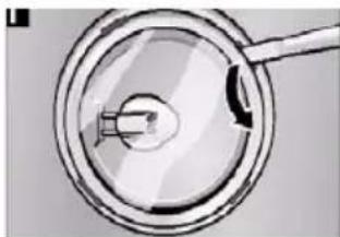
natural_image
Close-up of a magnifying glass with a handle and arrow, no visible text or symbolsWe thank you for your decision to purchase our product.
You device satisfies high expectations and is easy to operate. All the same, take the time to read this instruction manual. This will make you familiar with your device and allow you to use it optimally and free of problems. Text, images and information correspond to the technical state of the device at the time of printing this instruction manual. It is subject to changes in the sense of further development.
Please heed the safety instructions.
Type / Model Number
Vertica
The model number corresponds to the number on the type label.
Safety Instructions
This instruction manual contains important information that must be taken into account so that the exhaust hood and be installed and operated safely and without danger. Carefully store the instruction manual and installation instructions for later reference.
Intended Use
The exhaust hood may only be used to remove cooking vapors above cooking devices in private households. Any other use is deemed as other than intended. Improper use of the hood can cause harm to persons and objects. The exhaust hood may not be used to store objects such as bottles or spice containers or other loose objects.
Installation
This device may only be installed by authorized service personnel in compliance with all relevant regulations of the companies providing electricity as well as the building regulations of the respective countries. Please note the installation instructions during installation! Damaged devices may not be operated. Defective parts must be replaced by original parts. Repairs may only be conducted by authorized service technicians.
Risk of Poisoning!
During simultaneous operation of an exhaust hood for exhaust purposes and other heat producing appliances dependent upon the air in the room (e.g. wood, gas, oil or coal fueled devices) in one room, deadly flammable gases could be fed back into the room through negative pressure. Therefore, the operator must provide sufficient fresh air at all times. The negative pressure in the room may not be greater than 4 Pa (0.04 mbar). The exhaust may never be operated without a grease filter and must always be supervised while operated.
Risk of Fire!
Filters filled with too much grease carry a risk of fire. Only fry under an exhaust hood if there is constant supervision!
Be certain to clean the filter regularly! Cooking flambé style under the hood is not allowed! Gas devices may only be used under the exhaust hood with pots on them! If you are using more than 3 gas operated cooking devices at the same time, please run the exhaust hood at power level 2 or higher. This will prevent heat accumulation in the device.
Risk of Electrical Shock!
Please do not clean the hood with a steam cleaning device or a high pressure cleaner. The hood must be separated from the power supply during cleaning. Subject to technical changes!CAUTION: Accessible parts may become hot when used with cooking appliances.
General Functionality:
The exhaust hood has been specially developed for the exhaust of cooking vapors in private households. The rising cooking vapors are caught by the exhaust hood and removed via a grease filter through exhaust slits (with an additional active carbon filter in the case of air recirculation). For optical reasons, the front side of the exhaust hood is equipped with a special glass pane as well as titanium panels. The glass pane with a central recess is arranged on the wedge shaped hood body in such a manner that the titanium panels are flush with the glass recess. The titanium panels are arranged at intervals with each other, so that an exhaust vent is created. The grease filter is covered by the titanium panels. Access to the grease filter is provided by removing the titanium panels.
Illumination is installed on the underside of the hood. The hood body is made out of stainless steel or painted sheet metal in conjunction with glass and titanium for hygienic reasons. The exhaust power is regulated via the control panel. In addition, the illumination as well as the filter cleaning interval is displayed on the control panel. The illumination consists of two halogen illuminants. Both illuminants are galvanized and integrated flush into the hood body.
Product Description
1 Hood Body
2 Glass Pane
3 Illumination
4 Metal Filter
5 Titanium Panels
6 Magnet Holder
7 Lower Tower
8 Upper Tower
9 Control Panel
Control Panel
The control panel consists of 6 symbols:
- Exhaust Power
Control buttons: three levels (1 to 3) and an intensive level „int“.
Level 1 = lowest motor speed
Level 2 = middle motor speed
Level 3 = high motor speed
Level 4 = intensive level (motor switch to level 3 after 5 minutes)
2. Automatic Cool Down Period
Press the button with the clock symbol on it once and the exhaust hood will automatically cool down from level 3 to level 1 and turn off after approximately 15 minutes.
Illumination
Press the button with the light symbol to turn on the illumination. The illumination is turned off by pressing the button again. The illumination is dimmed by pressing and holding the button for a longer period. Brightness is raised again by another long press of the button.
4. Filter Cleaning Display
Clean the grease filter every 14 days. In the event of heavier use, clean the grease filter as soon as the „clock symbol“ begins to blink. Replace the cleaned filter and press the cool down button (clock symbol) and hold it for at least 5 seconds.
Cleaning and Care
Cleaning the Surface
Risk of Electrical Shock! Separate the exhaust hood from the electrical supply by removing the plug from the outlet or tripping the fuse. Please make sure that no water enters the device during cleaning. Early cleaning of the surfaces prevents toilsome removal of deep-rooted debris later. Please only use standard detergent or all purposes cleaners which are suitable for stainless steel/aluminum surfaces. Never use scouring cleaners or steel wool. After cleaning the hood, treat the stainless steel surfaces with an appropriate preserving agent. In the event of painted surfaces, only clean using a mild detergent and a very soft cloth. Clean the glass front with a standard glass cleaner and wipe it off with a soft cloth.
en
Remove / Clean the Grease Filter

Risk of Fire! The performance of the exhaust hood is affected by greasy debris; the risk of fire increases with the amount of deposits.
In order to avoid the risk of fire, be certain to regularly clean the metal filter.
natural_image
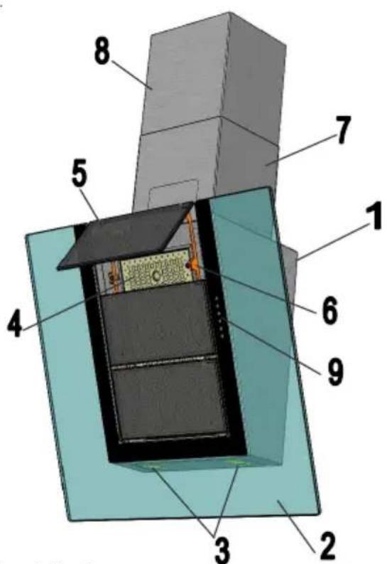
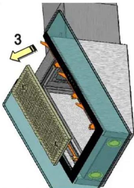
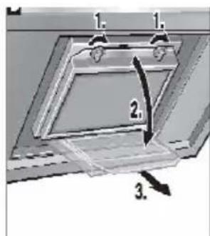
Diagram of a mechanical or architectural component with layered structure and directional arrow (no text or symbols)(see „filter cleaning display“). Clean the filter in a 14 day cycle, maximum. To do so, first remove the three titanium plates: 1 Press the titanium plates forward with both hands on the lower edge, 2 then push them upwards so that the titanium plates loosen from their catches and can be removed.
The titanium plates are held in place with magnets. 3 Now hold the metal filter by the grip holes with both hands and push forward. The metal filter is held in place with magnets.
The metal filter is best cleaned in a dishwasher with gentle dishwasher detergent. The manufacturer offers no guarantee in the event of possible discoloration through the use of aggressive cleaning products. Temperatures above 65 degrees should also be avoided. Attention: Please do not use any 3 phase cleaners or clean the filter in a commercial dishwasher. Cleaning with aggressive products such as benzene, acetone, trichloroethylene, et cetera will lead to the destruction of the filter! Replace the metal filter after cleaning, then replace the three titanium plates in reverse order, as was done during assembly.
natural_image
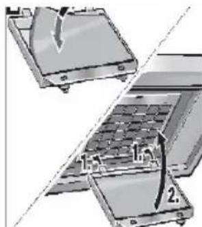
Diagram showing two views of a laptop with internal components and a labeled component (no text or symbols present)Change the Active Carbon Filter
(Only with Hood with Circulating Air Operation) Active carbon filters bind to odors that are contained in cooking vapors. As per usage, the filter must be exchanged after 3-6 months of operation.
- Press the catch in the direction of the arrows and let down the filter frame
- Change the active carbon filter
- Replace and secure the filter frame
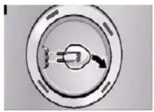
Changing Lamps
Disconnect the exhaust hood from the power supply! To change the halogen lamps, carefully remove the glass cover with a small screw driver, remove the bulb and replace it with a new bulb. Avoid direct contact between the bulb and the finger. Replace defective bulbs with new ones immediately.
natural_image
Circular mechanical component with a central shaft and arrow, no visible text or symbols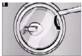
natural_image
Close-up of a magnifying glass with a small object inside, no visible text or symbolsMalfunctions
Please consult our customer service immediately if the following malfunctions occur:
- The exhaust hood is making unidentifiable noises and you cannot determine a malfunction after inspection;
- You determine that the motor is malfunctioning or defective, such as after hearing strange noises;
- The switch is not functioning properly.
Please be certain to provide the type designation of your model as well as the accompanying serial number. You will find this information on the type label. This is located inside the hood, near the filter.
Disposal
Packaging
The packaging of the exhaust hood is recyclable. Cardboard and polyethylene foil (PE) are used as packaging materials. These materials are environmentally compliant and should be disposed of as per the valid regulations of the respective location.
Exhaust Hood
Your community will inform you about the environmentally friendly disposal of old household appliances.
Environmental Instructions

All V-Zug models are labeled as per European Directive 2002/96/EG on Waste Electrical and Electronic Equipment (WEEE). This guideline provides the basic conditions valid for the EU-wide return and recycling of old appliances. Please consult your dealer for the current disposal methods.
Technical Information
Connection to the electrical network:
220-240V / 50-60 Hz, 600W, option 300W
Halogen Bulb Type:12V, 20W Sockel G/4 21520
natural_image
3D diagram of a mechanical assembly with layered components and an arrow indicating direction (no text or symbols)natural_image
Circular mechanical component with a central knob and arrow, no visible text or symbols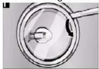
natural_image
Close-up of a magnifying glass with a handle and internal components (no text or symbols visible)natural_image
Diagram of a mechanical assembly with layered components and a numbered arrow indicating direction (no text or symbols present)natural_image
Two circular diagrams showing a mechanical component with arrows indicating direction, no text or symbols present.natural_image
Diagram of a mechanical assembly with layered components and a numbered arrow indicating direction (no text or symbols present)Замена лампы
natural_image
Circular diagram with a central connector and arrow, no visible text or symbols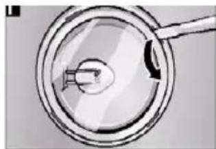
natural_image
Simple line drawing of a magnifying glass with a handle and arrow, no text or symbols presentLimpar as superfícies
natural_image
Diagram of a mechanical assembly with labeled component '3' and directional arrow (no readable text or symbols)natural_image
Circular diagram with a central connector and arrow, no visible text or symbols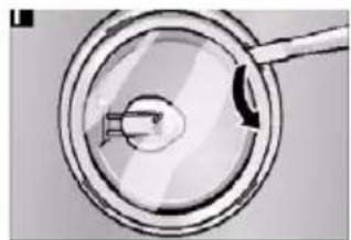
natural_image
Close-up of a magnifying glass with a small object inside, no visible text or symbols1. Fläkteffekt

natural_image
Diagram of a mechanical or electrical component with layered structure and labeled component '3' (no readable text or symbols)natural_image
Diagram showing two views of a laptop with a handle and internal components, no text or symbols presentByta lampa
natural_image
Circular mechanical component with a central pin and arrow, no visible text or symbols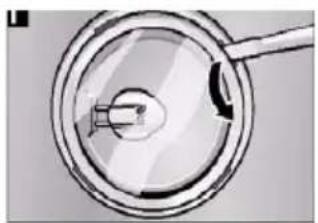
natural_image
Close-up of a magnifying glass with a handle, showing internal components (no text or symbols visible)Störningar
Fare for forgiftning!
1. Avtrekksytelse
natural_image
3D diagram of a mechanical assembly with layered components and an arrow indicating direction (no text or symbols)Bytte lys
natural_image
Two circular diagrams showing internal components with arrows, one open and one filled with a tool (no text or symbols)Feil

- Please heed the safety instructions.
- Safety Instructions
- Intended Use
- Installation
- Risk of Poisoning!
- Risk of Fire!
- Risk of Electrical Shock!
- General Functionality:
- Product Description
- Control Panel
- Automatic Cool Down Period
- Illumination
- Filter Cleaning Display
- Cleaning and Care
- Cleaning the Surface
- en
- Remove / Clean the Grease Filter
- Change the Active Carbon Filter
- Changing Lamps
- Malfunctions
- Disposal
- Packaging
- Exhaust Hood
- Environmental Instructions
- Technical Information
- Замена лампы
- Limpar as superfícies
- Fläkteffekt
- Byta lampa
- Störningar
- Fare for forgiftning!
- Avtrekksytelse
- Bytte lys
- Feil
Brand : V-ZUG
Model : Vertica
Category : Basket