PHS1200E - Effect machine Futurelight - Free user manual and instructions
Find the device manual for free PHS1200E Futurelight in PDF.

User questions about PHS1200E Futurelight
0 question about this device. Answer the ones you know or ask your own.
Ask a new question about this device
Download the instructions for your Effect machine in PDF format for free! Find your manual PHS1200E - Futurelight and take your electronic device back in hand. On this page are published all the documents necessary for the use of your device. PHS1200E by Futurelight.
USER MANUAL PHS1200E Futurelight
natural_image
Technical line drawing of a mechanical device with no visible text or symbolsMULTI-LANGUAGE-INSTRUCTIONS
Delivery includes 36
SAFETY INSTRUCTIONS.... 37
OPERATING DETERMINATIONS.... 38
DESCRIPTION OF THE DEVICE 39
Features 39
Overview 41
INSTALLATION 43
Installing/Replacing the lamp 43
Lamp adjustment....44
Inserting/Exchanging gobos....44
Transport securing 45
Rigging 45
DMX-512 connection / connection between fixtures.... 47
Connection with the mains 48
OPERATION......48
Stand Alone operation....48
DMX-controlled operation 48
Wireless DMX 49
Meaning of the LEDs and their colours 49
Installation of a wireless DMX-system 49
Log out one wireless receiver 49
Log out all wireless receivers from the sender....49
Addressing 49
DMX-protocol 50
Control Board 55
Function Mode 57
Information 57
Lamp Control....59
Personality....59
Reset function 61
Effect Adjust 61
Users mode set 61
Edit program....61
Error Messages....64
CLEANING AND MAINTENANCE 64
Replacing the fuse 65
TECHNICAL SPECIFICATIONS....66
Français
INTRODUCTION 67
This user manual is valid for the article number 51838400
You can find the latest update of this user manual in the Internet under:
High-Power Moving-Head
natural_image
Line drawing of a mechanical device with no visible text or symbols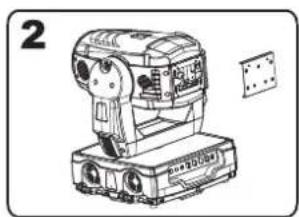
natural_image
Line drawing of a mechanical device with no visible text or symbols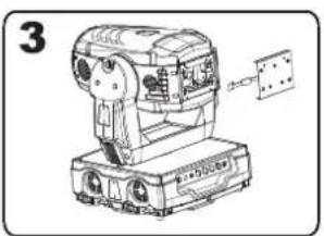
natural_image
Line drawing of a mechanical device with no visible text or symbols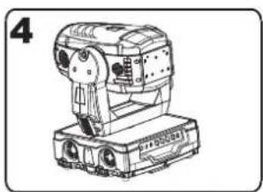
natural_image
Line drawing of a mechanical device with no visible text or symbolsnatural_image
Three hand-drawn diagrams showing a multi-ring container with internal segments and a small ring, no text or symbols present.
flowchart
graph TD
    A["Un-lock"] --> B["Lock"]
    B --> C["Un-lock"]
    style B fill:#fff,stroke:#000
    style C fill:#fff,stroke:#000
PAN-Sicherung:
natural_image
Technical line drawing of a mechanical assembly frame with four vehicle-mounted components (no text or symbols)natural_image
Technical line drawing of a mechanical device with no visible text or symbols
flowchart
graph LR
    A["Scene 10"] --> B["Scene 11"]
    B --> C["Scene 12"]
    C --> D["Scene 13"]
Part 2:
flowchart
graph LR
    A["Scene 8"] --> B["Scene 9"]
    B --> C["Scene 10"]
    C --> D["Scene 8"]
Part 3:
flowchart
graph LR
    A["Scene 12"] --> B["Scene 13"]
    B --> C["Scene 14"]
    C --> D["Scene 15"]
Deutsch
Fehlermeldungen
COLOR Wheel Rotation GOBO 1 Prism Rotation Fire wheel
Cyan COLOR GOBO Rotation 1 Focus error
Magenta COLOR Rotation GOBO 2 Iris
Keep this device away from rain and moisture! Unplug mains lead before opening the housing!
For your own safety, please read this user manual carefully before you initially start-up.
Every person involved with the installation, operation and maintenance of this device has to
- be qualified
- follow the instructions of this manual
- consider this manual to be part of the total product
- keep this manual for the entire service life of the product
- pass this manual on to every further owner or user of the product
- download the latest version of the user manual from the Internet
INTRODUCTION
Thank you for having chosen a FUTURELIGHT PHS-1200E. You will see you have acquired a powerful and versatile device.
Unpack your PHS-1200E and take it out of the flightcase.
Delivery includes
| 1 Device | |
| 1 User manual | |
| 1 Cable MC-50, 5m, black, XLR m/f,balanced 3022050N | |
| 1 PHILIPS MSR 1200SA/DE GOLD SFC 10-4 750h 89313015 | |
| 1 Flightcase for 1x PHS-1200 incl.reelboard 51836869 | |
| 2 FUTURELIGHT OC-1 Omega-clamp 51836995 | |
SAFETY INSTRUCTIONS
CAUTION!
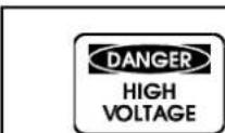
Be careful with your operations. With a dangerous voltage you can suffer a dangerous electric shock when touching the wires!
This device has left our premises in absolutely perfect condition. In order to maintain this condition and to ensure a safe operation, it is absolutely necessary for the user to follow the safety instructions and warning notes written in this user manual.

Important:
Damages caused by the disregard of this user manual are not subject to warranty. The dealer will not accept liability for any resulting defects or problems.
If the device has been exposed to drastic temperature fluctuation (e.g. after transportation), do not switch it on immediately. The arising condensation water might damage your device. Leave the device switched off until it has reached room temperature.
Please make sure that there are no obvious transport damages. Should you notice any damages on the A/C connection cable or on the casing, do not take the device into operation and immediately consult your local dealer.
This device falls under protection-class I. The power plug must only be plugged into a protection class I outlet. The voltage and frequency must exactly be the same as stated on the device. Wrong voltages or power outlets can lead to the destruction of the device and to mortal electrical shock.
Always plug in the power plug last. The power plug must always be inserted without force. Make sure that the plug is tightly connected with the outlet.
Never let the power-cord come into contact with other cables! Handle the power-cord and all connections with the mains with particular caution! Never touch them with wet hands, as this could lead to mortal electrical shock.
Never modify, bend, strain mechanically, put pressure on, pull or heat up the power cord. Never operate next to sources of heat or cold. Disregard can lead to power cord damages, fire or mortal electrical shock.
The cable insert or the female part in the device must never be strained. There must always be sufficient cable to the device. Otherwise, the cable may be damaged which may lead to mortal damage.
Make sure that the power-cord is never crimped or damaged by sharp edges. Check the device and the power-cord from time to time.
If extension cords are used, make sure that the core diameter is sufficient for the required power consumption of the device. All warnings concerning the power cords are also valid for possible extension cords.
Always disconnect from the mains, when the device is not in use or before cleaning it. Only handle the power-cord by the plug. Never pull out the plug by tugging the power-cord. Otherwise, the cable or plug can be damaged leading to mortal electrical shock. If the power plug or the power switch is not accessible, the device must be disconnected via the mains.
If the power plug or the device is dusty, the device must be taken out of operation, disconnected and then be cleaned with a dry cloth. Dust can reduce the insulation which may lead to mortal electrical shock. More severe dirt in and at the device should only be removed by a specialist.
There must never enter any liquid into power outlets, extension cords or any holes in the housing of the device. If you suppose that also a minimal amount of liquid may have entered the device, it must immediately be disconnected. This is also valid, if the device was exposed to high humidity. Also if the device is still
English
running, the device must be checked by a specialist if the liquid has reduced any insulation. Reduced insulation can cause mortal electrical shock.
There must never be any objects entering into the device. This is especially valid for metal parts. If any metal parts like staples or coarse metal chips enter into the device, the device must be taken out of operation and disconnected immediately. Malfunction or short-circuits caused by metal parts may cause mortal injuries.
During the initial start-up some smoke or smell may arise. This is a normal process and does not necessarily mean that the device is defective.
Danger of burning! Never install the device on a highly flammable surfaces (e.g. fair carpet)!
Caution: During the operation, the housing becomes very hot.
Do not switch the device on and off in short intervals as this would reduce the lamp's life.

HEALTH HAZARD!
Never look directly into the light source, as sensitive persons may suffer an epileptic shock (especially meant for epileptics)!
Keep away children and amateurs!
Never leave this device running unattended.
OPERATING DETERMINATIONS
This device is a moving-head spot for creating decorative effects. This product is only allowed to be operated with an alternating current of 230 V, 50 Hz and was designed for indoor use only.
This device is designed for professional use, e.g. on stages, in discotheques, theatres etc.
Lighting effects are not designed for permanent operation. Consistent operation breaks will ensure that the device will serve you for a long time without defects.
Do not shake the device. Avoid brute force when installing or operating the device.
Never lift the fixture by holding it at the projector-head, as the mechanics may be damaged. Always hold the fixture at the transport handles.
When choosing the installation-spot, please make sure that the device is not exposed to extreme heat, moisture or dust. There should not be any cables lying around. Please make sure that the unit cannot be touched or bumped. You endanger your own and the safety of others!
This device must never be operated or stockpiled in sourroundings where splash water, rain, moisture or fog may harm the device. Moisture or very high humidity can reduce the insulation and lead to mortal electrical shocks. When using smoke machines, make sure that the device is never exposed to the direct smoke jet and is installed in a distance of 0.5 meters between smoke machine and device. The room must only be saturated with an amount of smoke that the visibility will always be more than 10 meters.
The ambient temperature must always be between -5^ C and +45^ C. Keep away from direct insulation (particularly in cars) and heaters.
The relative humidity must not exceed 50 % with an ambient temperature of 45^ C.
This device must only be operated in an altitude between -20 and 2000 m over NN.
Never use the device during thunderstorms. Over voltage could destroy the device. Always disconnect the device during thunderstorms.
English
The symbol ·s m determines the minimum distance from lighted objects. The minimum distance between light-output and the illuminated surface must be more than this value.
The device must only be installed on a non-flammable surface. In order to safeguard sufficient ventilation, leave 50 cm of free space around the device. Please note that heat-sensitive objects may be deformed or damaged by the emitted heat.
Make sure that the area below the installation place is blocked when rigging, derigging or servicing the fixture.
For overhead use (mounting height >100 cm), always fix the fixture with an appropriate safety-rope. Fix the safety-rope at the correct fixation points only. The safety-rope must never be fixed at the transport handles!
Only operate the fixture after having checked that the housing is firmly closed and all screws are tightly fastened.
The lamp must never be ignited if the objective-lens or any housing-cover is open, as discharge lamps may expose and emit a high ultraviolet radiation, which may cause burns.
The maximum ambient temperature T_a = 45^ C must never be exceeded.
Operate the device only after having become familiarized with its functions. Do not permit operation by persons not qualified for operating the device. Most damages are the result of unprofessional operation! Please use the original packaging if the device is to be transported.
Please consider that unauthorized modifications on the device are forbidden due to safety reasons! Never remove the serial barcode from the device as this would make the guarantee void.
If this device will be operated in any way different to the one described in this manual, the product may suffer damages and the guarantee becomes void. Furthermore, any other operation may lead to dangers like short-circuit, burns, electric shock, lamp explosion, crash etc.
DESCRIPTION OF THE DEVICE
Features
High-Power Moving-Head
- With electronic ballast
- With integrated wireless receiver for W-DMX operation
• Extreme light output of 1200 W - Multi-lens-system for extremely bright and clear projections
• CMY colour mixture for indefinite colour variations - Motorised colour-wheel with 4 different, dichroic colour-filtres and white and additionally with correction-filter CTB and UV-filter
- The colour-wheel can be individually equipped with colours/gobos
- Rainbow-effect with adjustable speed in both directions
- Preprogrammed colour- and gobo-macros
- Variable colour temperature correction via CTO-filter
- Stepless frost-filter for fading the projection in or out
- Slot-in gobo-system for exchanging gobos without tools
- Two gobo-wheels with 5 rotating gobos plus open each
- All gobos can be interchanged
- With gobo-shake function
- Effect-wheel with rotating 2-facet prism, 3-facet prism, 5-facet prism, 3D-prism and open
- The prisms rotate in both directions and at different speeds, prism index function
- Macro-function for rotating gobos/rotating prism combinations
• Animation-wheel for fire-effect - Motorized focus
- Mechanic dimmer
- Motorized zoom
English
- Steplessly adjustable iris
- Preprogrammed variable/random iris/dimmer/shutter pulse effects
- Strobe-effect with 1-10 flashes per second via shutter
• Random strobe-effect
• Lightbeam with 17^-32^ radiation angle
• Coloured LCD-display - ESDC-Function (Easy Service Data Check) with battery-buffered Control Board for operation time readouts etc.
- Control-Board with LCD-display and encoder for adjusting the DMX-starting address, Pan/Tilt-Reverse, Program, Reset, lamp on/off, operating hours
- Software-update possible via optional accessory
- DMX-controlled operation or stand alone operation with Master/Slave-function
- 64 preprogrammed scenes in Program Run for stand alone operation
• Number of scenes in Program Run can be changed individually - The scenes in Program Run can be modified via the Control Board or via an external controller and loaded into the memory
- 8 built-in programs can be called up via DMX-controller
• Sound-controlled via built-in microphone
• Automatic position correction - 8 or 16 bit resolution
- Lamp already installed and adjusted from factory
- DMX-control via every standard DMX-controller
English
Overview
Faceplate
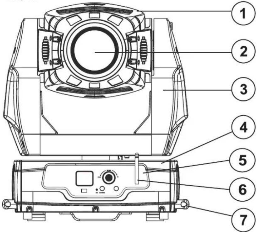
- Projector head
- Objective-lens
- Yoke
- Base
- Control Board
- DMX antenna
- Carrying handle
Rear panel
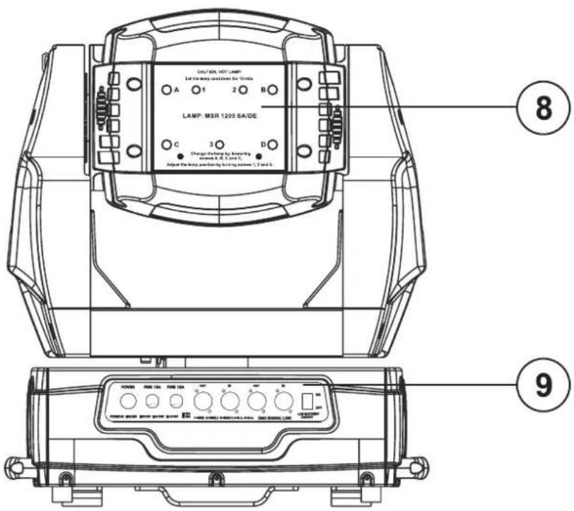
- Lamp system
- Connection panel
English
Control Board
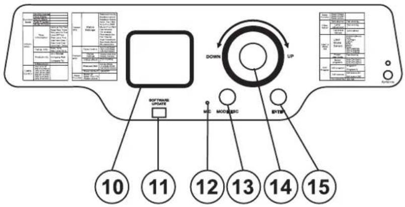
-
LCD-Display
-
Update-socket
-
Microphone
-
Mode/Escape button
-
Encoder
-
Enter button
Connection panel
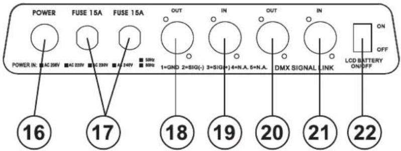
- Power supply socket
- Fuse holder
- 3-PIN DMX output socket
- 3-PIN DMX input socket
- 5-PIN DMX output socket
- 5-PIN DMX input socket
- LCD battery selector
INSTALLATION
Installing/Replacing the lamp
DANGER TO LIFE!
Only install the lamp with the device switched off! Unplug from mains before!
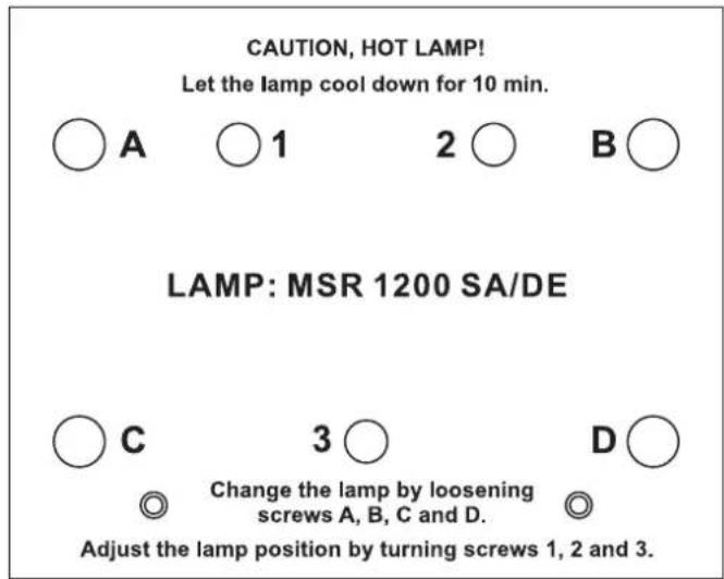
For the installation, you need one MSR 1200 SA/DE lamp.
The lamp must only be changed when wearing appropriate protective clothing (protection glasses, protection gloves, helmet with sight, leather apron).

CAUTION!
The lamp has to be replaced when it is damaged or deformed due to the heat!
The lamp life given by the manufacturer must never be exceeded. This is why you need to take notes on the operational time of the lamp or check the operating hour meter regularly and replace the lamp in time.
Keep exchanged lamp in a protective container and remove accordingly.
During the operation, the lamp reaches temperatures of up to 600^ C.
Before replacing the lamp, unplug mains lead and let the lamp cool down (approx. 10 minutes).
During the installation do not touch the glass-bulbs bare-handed! Please follow the lamp manufacturer's notes!
Do not install lamps with a higher wattage! Lamps with a higher wattage generate temperatures the device was not designed for. Damages caused by non-observance are not subject to warranty.
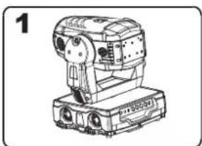
Procedure:
natural_image
Technical line drawing of a mechanical device with no visible text or symbols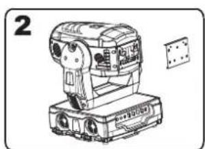
natural_image
Line drawing of a mechanical device with no visible text or symbols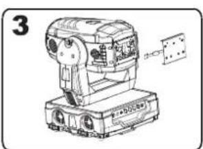
natural_image
Technical line drawing of a mechanical device with no visible text or symbols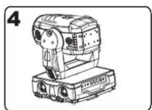
natural_image
Line drawing of a mechanical device with no visible text or symbolsStep 1: Unscrew the fixation screws A, B, C, D of the lamp system and carefully remove it from the housing.
Step 2: If replacing the lamp, remove the old lamp from the lamp holder.
Step 3: Insert the lamp into the lamp holder.
Step 4: Replace the lamp system in the housing and tighten the fixation screws.
Step 5: Adjust the lamp as described under lamp adjustment.

Do not operate this device with opened cover!
English
Lamp adjustment
The lampholder is aligned at the factory. Due to differences between lamps, fine adjustment may improve light performance.
Strike the lamp, open the shutter, set the dimmer intensity onto 100 % and direct the light towards a flat surface (wall). Center the hot-spot (the brightest part of the beam) using the 3 adjustment screws „1, 2, 3“ Turn one screw at a time to drag the hot-spot diagonally across the projected image. If you cannot detect a hot-spot, adjust the lamp until the light is even.
To reduce a hot-spot, pull the lamp in by turning all three screws „1, 2, 3“ clockwise 14 -turn at a time until the light is evenly distributed.
If the light is brighter around the edge than it is in the reflector. "Push" the lamp out by turning the light is bright and evenly distributed.
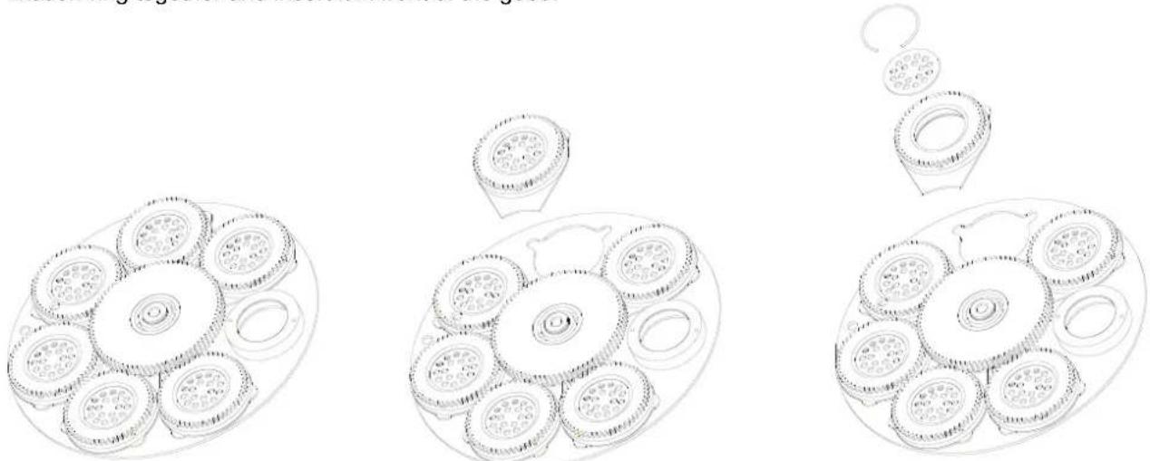
Inserting/Exchanging gobos
DANGER! Install the gobos with the device switched off only. Unplug from mains before!

If you wish to use other forms and patterns as the standard-gobos, or if gobos are to be exchanged, please follow the instructions below:
Remove the fixation-ring with an appropriate tool. Remove the gobo and insert the new gobo. Press the fixation-ring together and insert it in front of the gobo.
natural_image
Three hand-drawn diagrams showing a tray with circular compartments and a hanging ring, no text or symbols present.
Please note!
Slot-in gobo-system for exchanging gobos without tools! Inserting/Exchanging gobos as described above.

Transport securing
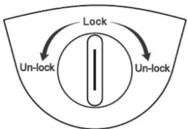
The PHS-1200E comes with locked transport securings in order to avoid damages.
Please note: All transport securing must be unlocked before operating the device!
TILT-securing:
Turn the two stop levers at the projector head from Lock to Unlock. Now, the projector head can be freely moved in the Y-direction.
flowchart
graph TD
    A["Lock"] --> B["Un-lock"]
    B --> C["Un-lock"]
    C --> A
PAN-securing:
Turn the stop levers at the bottom of the projector arm from Lock to Unlock. Now, the projector head can be freely moved in the X-direction.
Lock ←→ Un-lock
Before transporting the device, please turn all stop levers from Unlock to Lock.
Rigging

DANGER TO LIFE!
Please consider the EN 60598-2-17 and the respective national norms during the installation! The installation must only be carried out by an authorized dealer!
The installation of the projector has to be built and constructed in a way that it can hold 10 times the weight for 1 hour without any harming deformation.
The installation must always be secured with a secondary safety attachment, e.g. an appropriate catch net. This secondary safety attachment must be constructed in a way that no part of the installation can fall down if the main attachment fails.
When rigging, derigging or servicing the fixture staying in the area below the installation place, on bridges, under high working places and other endangered areas is forbidden.
The operator has to make sure that safety-relating and machine-technical installations are approved by an expert before taking into operation for the first time and after changes before taking into operation another time.
The operator has to make sure that safety-relating and machine-technical installations are approved by an expert after every four year in the course of an acceptance test.
English
The operator has to make sure that safety-relating and machine-technical installations are approved by a skilled person once a year.
Procedure:
The projector should be installed outside areas where persons may walk by or be seated.
IMPORTANT! OVERHEAD RIGGING REQUIRES EXTENSIVE EXPERIENCE, including (but not limited to) calculating working load limits, installation material being used, and periodic safety inspection of all installation material and the projector. If you lack these qualifications, do not attempt the installation yourself, but instead use a professional structural rigger. Improper installation can result in bodily injury and or damage to property.
The projector has to be installed out of the reach of people.
If the projector shall be lowered from the ceiling or high joists, professional trussing systems have to be used. The projector must never be fixed swinging freely in the room.
Caution: Projectors may cause severe injuries when crashing down! If you have doubts concerning the safety of a possible installation, do NOT install the projector!
Before rigging make sure that the installation area can hold a minimum point load of 10 times the projector's weight.

DANGER OF FIRE!
When installing the device, make sure there is no highly-inflammable material (decoration articles, etc.) within a distance of min. 0.5 m.

CAUTION!
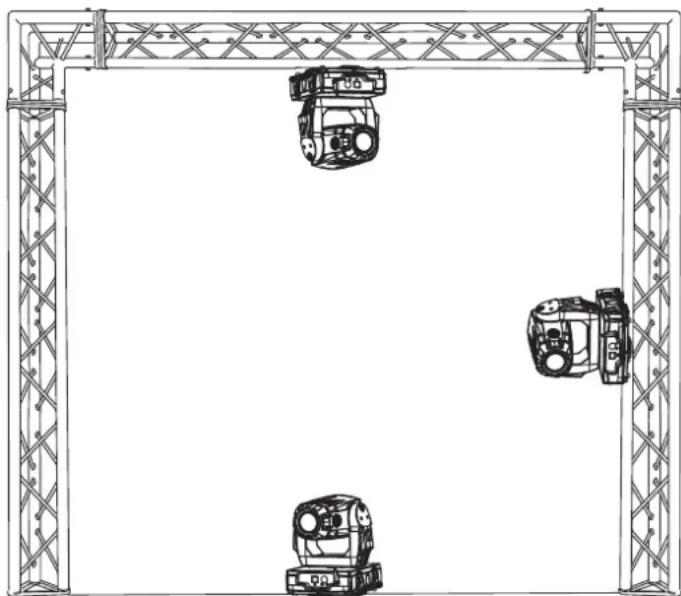
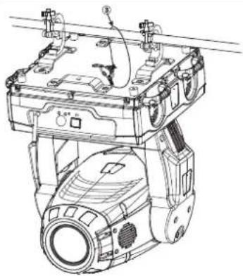
Use 2 appropriate clamps to rig the fixture on the truss. Follow the instructions mentioned at the bottom of the base. Make sure that the device is fixed properly! Ensure that the structure (truss) to which you are attaching the fixtures is secure.

natural_image
Technical line drawing of a mechanical assembly frame with three identical vehicle-mounted components (no text or symbols)The Moving-Head can be placed directly on the stage floor or rigged in any orientation on a truss without altering its operation characteristics (see the drawing).
The fixture's base enables to be mounted in two ways.
For overhead use (mounting height >100 cm), always install an appropriate safety bond.
You must only use safety bonds complying with DIN 56927, quick links complying with DIN 56926, shackles complying with DIN EN 1677-1 and BGV C1 carbines. The safety bonds, quick links, shackles and the carbines must be sufficiently dimensioned and used correctly in accordance with the latest industrial safety regulations (e.g. BGV C1, BGI 810-3).
Please note: for overhead rigging in public or industrial areas, a series of safety instructions have to be followed that this manual can only give in part. The operator must therefore inform himself on the current safety instructions and consider them.
The manufacturer cannot be made liable for damages caused by incorrect installations or insufficient safety precautions!
English
Install the safety bond by inserting the quick link in the hole on the bottom of the base Pull the safety bond over the trussing system etc. Insert the end in the quick link and tighten the fixation screw.
The maximum drop distance must never exceed 20 cm.
A safety bond which already hold the strain of a crash or which is defective must not be used again.

DANGER TO LIFE!
Before taking into operation for the first time, the installation has to be approved by an expert!
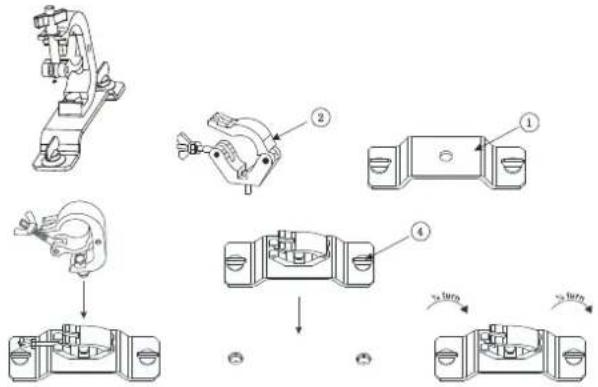
natural_image
Technical line drawing of a mechanical device with no visible text or symbols(1) Omega-holders
(2) Clamp
(3) Safety-rope
(4) Quick-lock fastener
Screw one clamp each via a M12 screw and nut onto the Omega-holders. Insert the quick-lock fasteners of the first Omega-holder into the respective holes on the bottom of the device. Tighten the quick-lock fasteners fully clockwise. Install the second Omega-holder.
DMX-512 connection / connection between fixtures
DMX-512 Controller

The wires must not come into contact with each other, otherwise the fixtures will not work at all, or will not work properly.


Please note, the starting address depends upon which controller is being used.

English
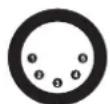
Only use a stereo shielded cable and 3-pin or 5-pin XLR-plugs and connectors in order to connect the controller with the device or one device with another.
Occupation of the XLR-connection:
DMX-output
XLR mounting-socket:
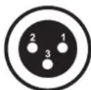
1: Ground
2: Signal (−)
3: Signal (+)
DMX-input
XLR mounting-plug:
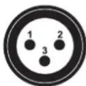
1: Ground
2: Signal (−)
3: Signal (+)
DMX-output
XLR mounting-socket:

1: Ground
2: Signal (−)
3: Signal (+)
DMX-input
XLR mounting-plug:
1: Ground
2: Signal (−)
3: Signal (+)
If you are using controllers with this occupation, you can connect the DMX-output of the controller directly with the DMX-input of the first fixture in the DMX-chain. If you wish to connect DMX-controllers with other XLR-outputs, you need to use adapter-cables.
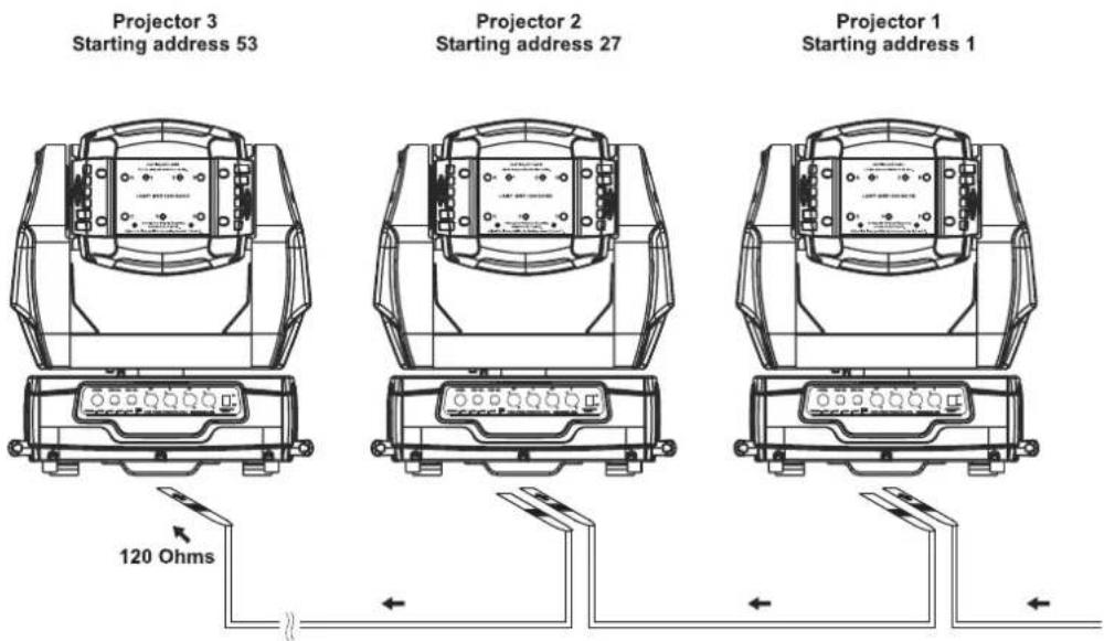
Building a serial DMX-chain:
Connect the DMX-output of the first fixture in the DMX-chain with the DMX-input of the next fixture. Always connect one output with the input of the next fixture until all fixtures are connected.
Caution: At the last device, the DMX-cable has to be terminated with a terminator. Solder a 120 Ω resistor between Signal (−) and Signal (+) into an XLR-plug and plug it in the DMX-output of the last device.
Connection with the mains
Connect the device to the mains with the power-plug.
The occupation of the connection-cables is as follows:
| Cable Pin International | |
| Brown Live L | |
| Blue Neutral N | |
| Yellow/Green Earth |  |
The earth has to be connected!
If the device will be directly connected with the local power supply network, a disconnection switch with a minimum opening of 3 mm at every pole has to be included in the permanent electrical installation.
The device must only be connected with an electric installation carried out in compliance with the IEC-standards. The electric installation must be equipped with a Residual Current Device (RCD) with a maximum fault current of 30 mA.
OPERATION
After you connected the effect to the mains, the PHS-1200E starts running. During the Reset, the motors are trimmed and the device is ready for use afterwards.
Stand Alone operation
In the Stand Alone mode, the PHS-1200E can be used without controller.
Disconnect the PHS-1200E from the controller and call the internal program.
Please refer to the instructions under Control Board, Functions, menu Auto program.
DMX-controlled operation
You can control the projectors individually via your DMX-controller. Every DMX-channel has a different occupation with different features. The individual channels and their features are listed under DMX-protocol.
English
Wireless DMX
For wireless data transmission you need a DMX-controller, a wireless sender and a wireless receiver or devices with wireless receiver, respectively.
If a device with wireless receiver is connected with a DMX-controller via cable, the device will be controlled by the cabled controller and not by the wireless transmitter.
Please note: Never connect a cabled controller if the device with wireless receiver is controlled by the wireless transmitter! Otherwise danger of interferences.
The wireless receiver has an internal memory function. If the device is switched off and on again, the receiver automatically logs into the transmitter.
Meaning of the LEDs and their colours
Wireless sender status-LED
Red/green flashes rapidly: Login-mode, every free wireless receiver is logging into the wireless sender.
Green permanently lit: the DMX-signal is present and transmitted.
Red/green flashes slowly: no DMX-signal, the radio link is being held.
Wireless receiver sender status-LED
Red permanently lit: not logged into a wireless sender (free).
Red/green flashes rapidly: Login-mode, the wireless receiver is logging into the wireless sender.
Green permanently lit: The wireless receiver is logged into the wireless sender. The DMX-signal is present and received.
Red/green flashes slowly: no DMX-signal, the radio link is being held.
Installation of a wireless DMX-system
- Connect the DMX-controller with the wireless sender.
- Switch on the DMX-controller, den the wireless sender and the wireless receiver or the devices with wireless receiver, respectively.
- Press and hold the sender's Function-button for less than 3 seconds. During the Login-mode, the sender's and receiver's red/green LEDs flash rapidly for approx. 5-10 seconds. As soon as the DMX-signal is transmitted, the sender's and receiver's green LED is permently lit. If there is no DMX-signal, the sender's and receiver's red/green LEDs flash slowly.
- Control the device via your DMX-controller.
Log out one wireless receiver
The procedure of logging out one wireless receiver depends on the respective device. The FUTURELIGHT projectors with wireless receiver are logged out via the Control Board, menu Set-WDMX-Rest. The FUTURELIGHT WDR-1 wireless receiver logs out by pressing and holding the receiver's Function-button for more than 5 seconds. As soon as the wireless receiver is logged out, the receiver's red LED is permently lit.
Log out all wireless receivers from the sender
Press and hold the sender's Function-button for at least 5 seconds. As soon as the wireless receivers are logged out, the receiver's red LED is permently lit.
Addressing
The Control Board allows you to assign the DMX starting address, which is defined as the first channel from which the PHS-1200E will respond to the controller.
If you set, for example, the address to channel 27, the PHS-1200E will use the channel 27 to 52 for control.
Please, be sure that you don't have any overlapping channels in order to control each PHS-1200E correctly and independently from any other fixture on the DMX-chain.
If several PHS-1200E are addressed similarly, they will work synchronically.
Trun the encoder for setting the desired starting address. Now you can start operating the PHS-1200E via your lighting controller.
English
Note:
After switching on, the device will automatically detect whether DMX 512 data is received or not. If there is no data received at the DMX-input, the display will flash.
This situation can occur if:
- the XLR plug (cable with DMX signal from controller) is not connected with the input of the device.
- the controller is switched off or defective, if the cable or connector is defective or the signal wires are swap in the input connector.
Note:
It's necessary to insert the XLR termination plug (with 120 Ohm) in the last lighting in the link in order to ensure proper transmission on the DMX data link.
DMX-protocol
Control-channel 1 - Horizontal movement (Pan) (within 630°)
Push slider up in order to move the head horizontally (PAN).
Gradual head adjustment from one end of the slider to the other (0-255, 128-center).
The head can be stopped at any position you wish.
Control-channel 2 - Vertical movement (Tilt) (within 265°)
Push slider up in order to move the head vertically (TILT).
Gradual head adjustment from one end of the slider to the other (0-255, 128-center).
The head can be stopped at any position you wish.
Control-channel 3 - Pan/Tilt-speed
| Decimal Hexad. Percentage S/F Feature | |||||||
| 0 | 225 | 00 E1 | 0% | 88% F | Decreasing speed | ||
| 226 | 235 | E2 | EB | 89% | 92% | S | Blackout at Pan/Tilt-movement |
| 236 | 245 | EC | F5 | 93% | 96% | S | Blackout at colour/gobo-change |
| 246 | 255 | F6 | FF | 96% | 100% | S | No function |
Control-channel 4 - Colour-wheel
Linear colour change following the movement of the slider.
In this way you can stop the colour-wheel in any position.
| Decimal Hexad. Percentage S/F Feature | |||||||
| 0 | 17 | 00 | 11 | 0% | 7% | S | Open / white |
| 18 | 35 | 12 | 23 | 7% | 14% S | Red | |
| 36 | 53 | 24 | 35 | 14% | 21% | S | Dark Blue |
| 54 | 71 | 36 | 47 | 21% | 28% S | Green | |
| 72 | 89 | 48 | 59 | 28% | 35% | S | Dark Yellow |
| 90 | 107 | 5A | 6B | 35% | 42% | S | CTB (Convert to blue) |
| 108 | 127 | 6C 7F | 42% | 50% | S UV-filter | ||
| 128 | 187 | 80 | BB | 50% | 73% | F | Forwards rainbow effect with decreasing speed |
| 188 | 193 | BC | C1 | 74% | 76% | S | No rotation |
| 194 | 255 | C2 | FF | 76% | 100% | F | Backwards rainbow effect with increasing speed |
Control-channel 5 - Cyan
| Decimal Hexad. Percentage S/F Feature | |||||||
| 0 | 255 | 00 | FF | 0% | 100% | F | Cyan (0=white, 255=cyan) |
Control-channel 6 - Magenta
| Decimal Hexad. Percentage S/F Feature | |||||||
| 0 | 255 | 00 | FF | 0% | 100% | F | Magenta (0=white, 255=magenta) |
Control-channel 7 - Yellow
Decimal Hexad. Percentage S/F Feature
| 0 | 255 | 00 | FF | 0% | 100% | F | Yellow | (0=white, 255=yellow) |
Control-channel 8 - CTO (Convet to orange)
Decimal Hexad. Percentage S/F Feature
| 0 | 255 | 00 | FF | 0% | 100% | F | CTO (0=white, 255=CTO) |
Control-channel 9 - CMY and dimmer speed
Decimal Hexad. Percentage S/F Feature
| 0 | 255 | 00 | FF | 0% | 100% | F | Speed | adjustment max to min |
Control-channel 10 - CMY colour macros
Decimal Hexad. Percentage S/F Feature
| 0 | 7 00 | 07 0% | 3% | S Neutral | |||
| 8 | 15 | 08 | 0F | 3% | 6% | S | Macro 1 |
| 16 | 23 10 | 17 | 6% | 9% | S Macro 2 | ||
| 24 | 31 | 18 | 1F | 9% | 12% | S | Macro 3 |
| 32 | 39 | 20 | 27 | 13% | 15% | S | Macro 4 |
| 40 | 47 | 28 | 2F | 16% | 18% | S | Macro 5 |
| 48 | 55 | 30 | 37 | 19% | 22% | S | Macro 6 |
| 56 | 63 | 38 | 3F | 22% | 25% | S | Macro 7 |
| 64 | 71 | 40 | 47 | 25% | 28% | S | Macro 8 |
| 72 | 79 | 48 | 4F | 28% | 31% | S | Macro 9 |
| 80 | 87 | 50 | 57 | 31% | 34% | S | Macro 10 |
| 88 | 95 | 58 | 5F | 35% | 37% | S | Macro 11 |
| 96 | 103 | 60 | 67 | 38% | 40% | S | Macro 12 |
| 104 | 111 | 68 | 6F | 41% | 44% | S | Macro 13 |
| 112 | 119 | 70 | 77 | 44% | 47% | S | Macro 14 |
| 120 | 127 | 78 | 7F | 47% | 50% | S | Macro 15 |
| 128 | 135 | 80 | 87 | 50% | 53% | S | Macro 16 |
| 136 | 143 | 88 | 8F | 53% | 56% | S | Macro 17 |
| 144 | 151 | 90 | 97 | 56% | 59% | S | Macro 18 |
| 152 | 159 | 98 | 9F | 60% | 62% | S | Macro 19 |
| 160 | 167 | A0 | A7 | 63% | 65% | S | Macro 20 |
| 168 | 175 | A8 | AF | 66% | 69% | S | Macro 21 |
| 176 | 183 | B0 | B7 | 69% | 72% | S | Macro 22 |
| 184 | 191 | B8 | BF | 72% | 75% | S | Macro 23 |
| 192 | 199 | C0 | C7 | 75% | 78% | S | Macro 24 |
| 200 | 207 | C8 | CF | 78% | 81% | S | Macro 25 |
| 208 | 215 | D0 | D7 | 82% | 84% | S | Macro 26 |
| 216 | 223 | D8 | DF | 85% | 87% | S | Macro 27 |
| 224 | 231 | E0 | E7 | 88% | 91% | S | Macro 28 |
| 232 | 239 | E8 | EF | 91% | 94% | S | Macro 29 |
| 240 | 247 | F0 | F7 | 94% | 97% | S | Macro 30 |
| 248 | 255 | F8 | FF | 97% | 100% | S | Random CMY |
Control-channel 11 - Rotating gobo-wheel, gobo shake 1
Decimal Hexad. Percentage S/F Feature
| 0 | 14 00 | 0E | 0% 5 | % S Open | |||
| 15 | 29 | 0F | 1D | 6% | 11% | S | Gobo 1 |
| 30 | 44 | 1E | 2C | 12% | 17% | S | Gobo 2 |
English
| 45 | 59 2D | 3B | 18% | 23% S | Gobo 3 | ||
| 60 | 74 3C | 4A | 24% | 29% S | Gobo 4 | ||
| 75 | 89 4B | 59 | 29% | 35% S | Gobo 5 | ||
| 90 | 109 | 5A | 6D | 35% | 43% | F | Gobo 1 shake with increasing speed |
| 110 | 129 | 6E | 81 | 43% | 51% | F | Gobo 2 shake with increasing speed |
| 130 | 149 | 82 | 95 | 51% | 58% | F | Gobo 3 shake with increasing speed |
| 150 | 169 | 96 | A9 | 59% | 66% | F | Gobo 4 shake with increasing speed |
| 170 | 189 | AA BD | 67% | 74% | F Gobo | 5 shake with increasing speed | |
| 190 | 255 | BE FF | 75% | 100% | F Cont. | gobo | -wheel rotation with increasing speed |
Control-channel 12 - Rotating gobo index, gobo rotation 1
| Decimal | Hexad. | Percentage | S/F | Feature | |||
| 0 | 127 | 00 | 7F | 0% | 50% | S | Gobo indexing |
| 128 | 187 | 80 | BB | 50% | 73% | F | Forwards gobo rotation with decreasing speed |
| 188 | 193 | BC | C1 | 74% | 76% | S | No rotation |
| 194 | 255 | C2 | FF 76% | 100% | F Backwards | gobo rotation with increasing speed | |
Control-channel 13 - Rotating gobo-wheel, gobo shake 2
| Decimal | Hexad. | Percentage | S/F | Feature | |||
| 0 | 14 | 00 | 0E | 0% | 5% | S | Open |
| 15 | 29 | 0F | 1D | 6% | 11% | S | Gobo 1 |
| 30 | 44 1E | 2C | 12% | 17% S | Gobo 2 | ||
| 45 | 59 2D | 3B | 18% | 23% S | Gobo 3 | ||
| 60 | 74 3C | 4A | 24% | 29% S | Gobo 4 | ||
| 75 | 89 4B | 59 | 29% | 35% S | Gobo 5 | ||
| 90 | 109 | 5A | 6D | 35% | 43% | F | Gobo 1 shake with increasing speed |
| 110 | 129 | 6E | 81 | 43% | 51% | F | Gobo 2 shake with increasing speed |
| 130 | 149 | 82 | 95 | 51% | 58% | F | Gobo 3 shake with increasing speed |
| 150 | 169 | 96 | A9 | 59% | 66% | F | Gobo 4 shake with increasing speed |
| 170 | 189 | AA BD | 67% | 74% | F Gobo | 5 shake with increasing speed | |
| 190 | 255 | BE FF | 75% | 100% | F Cont. | gobo- | -wheel rotation with increasing speed |
Control-channel 14 - Rotating gobo index, gobo rotation 2
| Decimal | Hexad. | Percentage | S/F | Feature | |||
| 0 | 127 | 00 | 7F | 0% | 50% | S | Gobo indexing |
| 128 | 187 | 80 | BB | 50% | 73% | F | Forwards gobo rotation with decreasing speed |
| 188 | 193 | BC | C1 | 74% | 76% | S | No rotation |
| 194 | 255 | C2 | FF 76% | 100% | F Backwards | gobo rotation with increasing speed | |
Control-channel 15 - Animation-wheel for fire-effect
| Decimal | Hexad. | Percentage | S/F | Feature | |||
| 0 | 7 | 00 | 07 | 0% | 3% | S | Open |
| 8 | 127 | 08 | 7F | 3% | 50% | F | Forwards rotation with decreasing speed |
| 128 | 135 | 80 | 87 | 50% | 53% S | No rotation | |
| 136 | 255 | 88 | FF | 53% | 100% | F | Backwards rotation with increasing speed |
Control-channel 16 - Prism-wheel
| Decimal | Hexad. | Percentage | S/F | Feature | ||||
| 0 | 25 | 00 | 19 | 0% | 10% | S Open | ||
| 26 | 51 | 1A | 33 | 10% | 20% S | 2-facet | prism | |
| 52 | 77 | 34 | 4D | 20% | 30% S | 3-facet | prism | |
| 78 | 103 | 4E | 67 | 31% | 40% S | 5-facet | prism | |
English
| 104 | 127 | 68 | 7F | 41% | 50% S | 3D-prism | |
| 128 | 135 | 80 | 87 | 50% | 53% S | Macro 1 | |
| 136 | 143 | 88 | 8F | 53% | 56% S | Macro 2 | |
| 144 | 151 | 90 | 97 | 56% | 59% S | Macro 3 | |
| 152 | 159 | 98 | 9F | 60% | 62% S | Macro 4 | |
| 160 | 167 | A0 | A7 | 63% | 65% S | Macro 5 | |
| 168 | 175 | A8 | AF | 66% | 69% S | Macro 6 | |
| 176 | 183 | B0 | B7 | 69% | 72% S | Macro 7 | |
| 184 | 191 | B8 | BF | 72% | 75% S | Macro 8 | |
| 192 | 199 | C0 | C7 | 75% | 78% S | Macro 9 | |
| 200 | 207 | C8 | CF | 78% | 81% S | Macro 10 | |
| 208 | 215 | D0 | D7 | 82% | 84% S | Macro 11 | |
| 216 | 223 | D8 | DF | 85% | 87% S | Macro 12 | |
| 224 | 231 | E0 | E7 | 88% | 91% S | Macro 13 | |
| 232 | 239 | E8 | EF | 91% | 94% S | Macro 14 | |
| 240 | 247 | F0 | F7 | 94% | 97% S | Macro 15 | |
| 248 | 255 | F8 | FF | 97% | 100% S | Macro 16 |
Control-channel 17 - Rotating prism index, prism rotation
| Decimal | Hexad. | Percentage | S/F | Feature | ||||
| 0 | 127 | 00 | 7F | 0% | 50 | % S Pr | sm indexing | |
| 128 | 187 | 80 | BB | 50% | 73% | F | Forwards | prism rotation with decreasing speed |
| 188 | 193 | BC | C1 | 74% | 76% | S | No rotation | |
| 194 | 255 | C2 | FF | 76% | 100% | F Backwards | prism rotation with increasing speed | |
Control-channel 18 - Focus
| Decimal | Hexad. | Percentage | S/F | Feature | |||
| 0 | 255 | 00 | FF | 0% | 100% | F | Continuous adjustment from near to far |
Control-channel 19 - Stepless Zoom
| Decimal | Hexad. | Percentage | S/F | Feature | |||
| 0 | 255 | 00 | FF | 0% | 100% | F | Zoom adjustment from small to big |
Control-channel 20 - Iris
| Decimal | Hexad. | Percentage | S/F | Feature | |||
| 0 | 191 | 00 | BF | 0% | 75% | F | Max. diameter to min. diameter |
| 192 | 223 | C0 | DF | 75% | 87% | F | Pulse opening with decreasing speed |
| 224 | 255 | E0 | FF | 88% | 100% | F | Pulse closing with increasing speed |
Control-channel 21 - Shutter, strobe
| Decimal | Hexad. | Percentage | S/F | Feature | |||
| 0 | 31 | 00 | 1F | 0% | 12% | S | Shutter closed |
| 32 | 63 20 | 3F | 13% | 25% S | No function (shutter open) | ||
| 64 | 95 | 40 | 5F | 25% | 37% | F | Strobe-effect with increasing speed |
| 96 | 127 | 60 7F | 38% | 50% S | No function (shutter open) | ||
| 128 | 159 | 80 | 9F | 50% | 62% | F | Pulse-effect in sequences |
| 160 | 191 | A0 BF | 63% | 75% $ | No function (shutter open) | ||
| 192 | 223 | C0 | DF | 75% | 87% | F | Random strobe-effect with increasing speed |
| 224 | 255 | E0 FF | 88% | 100% | S No function (shutter open) | ||
Control-channel 22 - Dimmer intensity
| Decimal Hexad. Percentage S/F Feature | |||||||
| 0 | 255 | 00 | FF | 0% | 100% | F | Gradual adjustment of the dimmer intensity from 0 to 100 % |
Control-channel 23 - Frost
| Decimal Hexad. Percentage S/F Feature | |||||||
| 0 | 191 | 00 BF | 0% | 75% F | Frost from 0 to 100 % | ||
| 192 | 223 | C0 DF | 75% | 87% F | Pulse | opening with decreasing speed | |
| 224 | 254 | E0 | FE | 88% | 100% | F | Pulse closing with increasing speed |
| 255 | 255 | FF | FF | 100% | 100% | F | 100 % frost |
Control-channel 24 - Switching the lamp, Reset, internal programs
| Decimal Hexad. Percentage S/F Feature | |||||||
| 0 | 31 | 00 | 1F | 0% | 12% | S | Normal colour-change, search position via shortest distance |
| 32 | 63 | 20 | 3F | 13% | 25% | S | Colour-change at every position, search position via shortest distance |
| 64 | 79 | 40 | 4F | 25% | 31% | S | Lamp on |
| 80 | 85 | 50 | 55 | 31% | 33% | S | Reset all motors |
| 86 | 87 | 56 | 57 | 34% | 34% | S | Reset only Pan/Tilt |
| 88 | 89 | 58 | 59 | 35% | 35% | S | Reset only colors |
| 90 | 91 | 5A | 5B | 35% | 36% | S | Reset only gobo |
| 92 | 93 | 5C | 5D | 36% | 36% | S | Reset only shutter and/or dimmer |
| 94 | 95 | 5E | 5F | 37% | 37% | S | Reset other motors |
| 96 | 111 | 60 | 6F | 38% | 44% | S | Internal program 1 (Edit Program Scene 1 - 8) |
| 112 | 127 | 70 | 7F | 44% | 50% | S | Internal program 2 (Edit Program Scene 9 - 16) |
| 128 | 143 | 80 | 8F | 50% | 56% | S | Internal program 3 (Edit Program Scene 17 - 24) |
| 144 | 159 | 90 | 9F | 56% | 62% | S | Internal program 4 (Edit Program Scene 25 - 32) |
| 160 | 175 | A0 | AF | 63% | 69% | S | Internal program 5 (Edit Program Scene 33 - 40) |
| 176 | 191 | B0 | BF | 69% | 75% | S | Internal program 6 (Edit Program Scene 41 - 48) |
| 192 | 207 | C0 | CF | 75% | 81% | S | Internal program 7 (Edit Program Scene 49 - 56) |
| 208 | 223 | D0 | DF | 82% | 87% | S | Internal program 8 (Edit Program Scene 57 - 64) |
| 224 | 239 | E0 | EF | 88% | 94% | S | Lamp off |
| 240 | 255 | F0 | FF | 94% | 100% | S | Music control |
Control-channel 25 - Pan-movement with 16 Bit-resolution
Control-channel 26 - Tilt-movement with 16 Bit-resolution
Control Board
The Control Board offers several features: you can simply set the starting address, switch on and off the lamp, run the pre-programmed program or make a reset.
The main menu is accessed by pressing Mode/Esc until the display is lit. Browse through the menu by turning the encoder. Press Enter in order to select the desired menu. You can change the selection by turning the encoder. Press Enter in order to confirm. You can leave every mode by pressing Mode/Esc-. The functions provided are described in the following sections.
Default settings shaded.
| Main menu Sub m | menu Display Function | |||
| Function Mode | Set DMX address A001~ AXXX DMX address setting | |||
| Value display PAN Moving ... DMX value display | ||||
| Set to Slave | Slave 1, Slave 2, Slave 3 | Slave setting | ||
| Auto program Master/Alone Auto program | ||||
| Music control Master/Alone Music control | ||||
| Information | Time information | Individual run time XXXX (hours) | Individual fixture running time | |
| Total run time XXXX (hours) Fixture running time | ||||
| Total lamp on time XXXX (hours) Lamp running time | ||||
| Lamp off time XXXX (minutes) Lamp off time | ||||
| Clear lamp time | ON/OFF | Clear lamp time | ||
| Total fans clear t. XXXX (days) | Fan operating days since last cleaning | |||
| Clear fans clear t. | ON/OFF | Clear fan operating days | ||
| Fans clear t. setup | OFF/250 (days) | Select fan maintenance interval | ||
| Temp. info. | Base Temp | XX°C | Ambient temperature | |
| Near lamp Temp | XXX°C | Inside temperature | ||
| Product info. | Unit model | Unit model | ||
| Company WEB | Company WEB | |||
| Company Tel | Company Tel | |||
| Software version | Display ... Ver. 1.0 ... | Software version of each IC | ||
| Lamp Control | Lamp on or off ON/OFF | Lamp on/off | ||
| Lamp on by power on | ON/OFF | Lamp on/off / Power | ||
| Lamp on via DMX | ON/OFF | Lamp on via DMX | ||
| Lamp off via DMX | ON/OFF | Lamp off via DMX | ||
| Lamp off if no DMX | OFF, OFF~19M | Lamp off if no DMX | ||
| Lamp on at temp. | 45 °C, 20-79C | Lamp restart at temp. | ||
| Lamp off at temp. | 130 °C, 80-139C | Lamp off at temp. | ||
| Personality | Status settings | Blackout moving | ON/OFF | Blackout with PAN/TILT movement or color/gobo wheel moving |
| Blackout colors ON/OFF | ||||
| Blackout gobos ON/OFF | ||||
| Addr. via DMX ON/OFF | Addr. via DMX | |||
| Run if no DMX Auto/Music/Close/Hold | Run if no DMX | |||
| Battery Charge ON/ | OFF | Battery charger | ||
| PAN Reverse ON/OFF | Reverse movement | |||
| TILT Reverse ON/OFF | ||||
| Fine resolution ON/OFF | 16-bit movement switch from 16 bit to 8 bit resolution | |||
| PAN degree 630/540 | Select PAN-angle 630° or 540° | |||
| Movement feedback ON/OFF | Automatic PAN/TILT calibration | |||
| Movement speed | Movement Speed 1 ~ 4 | Adjust PAN/TILT speed | ||
| Mic sensitivity 70 %, 0~99% | Mic sensitivity | |||
| Fans Control | Auto fans speed | Adjust fan speed | ||
| High fans speed | ||||
| Low fans speed | ||||
| Display settings | Display close time 05 M, 02-59 Display | shutoff time | ||
| Display intensity | 70 %, 50~99% | LCD brightness | ||
| Initial effect | PAN Moving ... | PAN Moving=XXX ... | Initial effect position | |
| Wireless DMX | Activate WDMX | Activate W-DMX | ||
| De-activate WDMX | De-activate W-DMX | |||
| Rest WDMX Memory | Logout from sender | |||
| Reset default ON/OFF | Restore factory sett. | |||
| Reset function | Reset All | Reset all motors | ||
| Reset PAN/TILT | Reset only PAN/TILT | |||
| Reset Colors | Reset only colors/ CMY + CTO module | |||
| Reset Gobos | Reset Gobos | |||
| Reset Shutter | Reset only shutter and/or dimmer | |||
| Reset Others | Reset other motors | |||
| Effect Adjust | Test channel | PAN Moving ... | Test function | |
| Lamp adjustment | PAN Moving ... | PAN Moving=XXX ... | Lamp adjustment | |
| Calibrate Values | --Password--Color wheel ... | Password=XXX Color wheel=XXX | Wheel adjustment to standard position password „050“ | |
| User's Mode Set | User mode select | XXXXXX (Band)F, E, S, M, R,User mode A,User mode B,User mode C | User's mode to change channel numbers | |
| Preset user mode | PAN Moving ... | PAN Mov. = CH01 ... | Preset User modes | |
English
| Edit Program | Select Programs | Auto Pro Part 1Auto Pro Part 2Auto Pro Part 3 | Progr. 1-10Progr. 1-10Progr. 1-10 | Program 1Program 2Program 3 | Select programs to be run |
| Edit program | Program 1:Program 10 | Program TestStart stepEnd step | ("Step XX")Startstep=xxxEndstep=xxx | Testing programProgram in loopSave and exit | |
| Edit scenes | Edit scene 001:Edit scene 250 | Pan,Tilt, ...--SceneTime--Input by outside | Pan=XXXTIME=XX.XS | Save and automatically return manual scenes edit | |
| Auto scenes Rec. XXX~XXX Automat. scenes rec | |||||
Function Mode
DMX address setting
With this function, you can adjust the desired DMX-address via the Control Board.
- Select "Set DMX address" via the encoder.
- Press the Enter-button, adjust the DMX address by turning the encoder.
- Press the Enter-button to confirm.
- Press the Mode/Esc-button in order return to the main menu.
Display the DMX 512 value of each channel
With this function you can display the DMX 512 value of each channel. The display automatically shows the channel with a value changing.
Slave setting
With this function, you can define the device as slave. You can choose one of three different Slave programs. For further information see „Edit Program“ - „Select Programs“
Auto program
With this function, you can run the internal program. You can select the desired program under "Select program". You can set the number of steps under "Edit program". You can edit the individual scenes under "Edit scenes". With this function, you can run the individual scenes either automatically, i.e. with the adjusted Step-Time. The selection "Alone" means Stand Alone-mode and "Master" that the device is defined as master.
Music control
With this function, you can run the internal program sound-controlled. The selection "Alone" means Stand Alone-mode and "Master" that the device is defined as master.
Information
Time information
Individual run time
With this function, you can display the temporary running time of the device from the last power on. The display shows "XXXX", "X" stands for the number of hours. The counter is reset after turning the device off.
Total run time
With this function, you can display the running time of the device. The display shows "XXXX", "X" stands for the number of hours.
Total lamp on time
With this function, you can display the running time of the lamp. The display shows "XXXX", "X" stands for the number of hours.
English
Lamp off time (in minutes)
With this function, you can display the temporary running time of the lamp from the last lamp on. The display shows "XXXX", "X" stands for the number of minutes. The counter is reset after turning the lamp off.
Clear lamp time
With this function you can clear the running time of the lamp. Please clear the lamp time every time you replace the lamp.
- Select "Clear lamp time" by turning the encoder.
- Press the Enter button, the display shows "ON" or "OFF".
- Press the Enter button to confirm.
- Press the Mode/Esc button in order to return to the main menu.
Fan operating days since last cleaning
With this function you can display the operating days since the fan/anti-dust filter was cleaned last.
The display shows "XXXX", "X" stands for the number of days.
Clear fan operating days
With this function you can clear the operating days of the fan. Please effect this function after every cleaning procedure of the fan/anti-dust filter.
- Select "Clear fans clear t." by turning the encoder.
- Turn the encoder, the display indicates "ON" or "OFF".
- Press the Enter button to confirm.
- Press the Mode/Esc button in order to return to the main menu.
Select fan maintenance interval
With this function you can select the desired maintenance interval of the fan/anti-dust filter.
You can select either OFF or 1-250 days. We recommend a cleaning procedure every 90 days.
- Select“ Fans clear t. setup ” by turning the encoder.
- Press the Enter button, the display indicates "OFF".
- Turn the encoder, to adjust the desired number of days or "OFF".
- Press the Enter button to confirm.
- Press the Mode/Esc button in order to return to the main menu.
Temp. Info.
Base Temp
With this function you can display the temperature in the projector base (near LCD-display) in Celsius.
Near lamp Temp
With this function you can display the temperature in the projector-head (near CMY-filter) in Celsius.
Product Info.
Within this menu, you can find the data concerning the type, Internet and phone number.
Software version
With this function you can display the software version of the device.
- Select "Software version" by turning the encoder.
- Press the enter-button, the display shows "V-X.X", "X.X" stands for the version number, e.g. "V-1.0", "V-2.6".
- Press the Mode/Esc-button in order to return to the main menu.
English
Lamp Control
Lamp on or off
With this function you can switch the lamp on or off via the Control Board.
- Select "Lamp on or off" by turning the encoder.
- Press the enter-button, the display shows "ON" or "OFF".
- Turn the encoder to select "ON" if you wish to strike the lamp or "OFF" in order to switch it off.
- Press the enter-button to confirm.
- Press the Mode/Esc-button in order to return to the main menu.
Lamp on by power on
With this function you can select if the lamp will be switched on when switching the power on. Select “ON” by turning the encoder if you wish to enable this function or “OFF” if you don’t.
Lamp on via external controller
With this function you can select if you can switch the lamp on via an external controller (DMX-channel 24, value 64-79). Select "ON" by turning the encoder if you wish to enable this function or "OFF" if you don't.
Lamp off via external controller
With this function you can select if you can switch the lamp off via an external controller (DMX-channel 24, value 224-239). Select "ON" by turning the encoder if you wish to enable this function or "OFF" if you don't.
Lamp off if no DMX
With this function you can select to switch off the lamp off automatically if there is no DMX signal.
Lamp on at temp.
With this function you can set the inside temperature from which the projector will restrike the lamp after automatic lamp shutoff.
Lamp off at temp.
With this function you can set the inside temperature at which the projector will automatically switch the lamp off. Turn the encoder to select the maximum inside temperature between 80^ C and 139^ C. Inside temperatures below 90^ C are not critical. 90^ C and more should lead to the lamp being switched off. Please note that the outside temperature should not exceed 45^ C.
Personality
Status settings
Blackout moving
With this function, you can switch the DMX-function Blackout with Pan/Tilt-movement (DMX-channel 3, values 226-235) on or off.
Blackout colors/gobos
With this function, you can switch the DMX-function Blackout at colour/gobo-change (DMX-channel 3, values 236-245) on or off.
Addr. via DMX
With this function, you can adjust the desired DMX-address via an external controller.
- Select "Addr. via DMX" by turning the encoder.
- Press the enter-button, the display shows "ON" or "OFF".
- Turn the encoder to select "ON" if you wish to enable this function or "OFF" if you don't.
- Press the enter-button to confirm.
- Press the Mode/Esc-button in order to return to the main menu.
- On the controller, set the DMX-value of channel 1 to "7".
- Set the DMX-value of channel 2 to "7" or "8". When set to "7" you can adjust the starting address between 1 and 255. When set to "8" you can adjust the starting address between 256 and 511.
- Set the DMX-value of channel 3 to the desired starting address. If you want to set the starting address to 57, set channel 1 to "7", channel 2 to "7" and channel 3 to "57". If you want to set the starting address to 420, set channel 1 to "7", channel 2 to "8" and channel 3 to "164" (256+164=420).
- Wait for approx. 20 seconds and the unit will carry out a reset. After that, the new starting address is set.
English
Run if no DMX
With this function, you can set different modes if there is no DMX-signal.
- Select "Close, Hold, Auto or Music if no DMX" by turning the encoder.
- Press the enter-button, the display shows "ON" or "OFF".
- Turn the encoder to select "ON" if you wish to enable this function or "OFF" if you don't.
- Press the Enter-button to confirm.
- Press the Mode/Esc-button in order to return to the main menu.
Close if no DMX
With this function, you can close the shutter and set the device to center position if there is no DMX-signal. This mode equals the settings Auto if no DMX = OFF and Music if no DMX = OFF.
Hold if no DMX
With this function, the device remains in the last received DMX-program if there is no DMX-signal.
Auto run if no DMX
With the function "Auto run if no DMX", you can set the device to auto run if there is no DMX-signal.
Music control if no DMX
With the function “Music control if no DMX”, you can set the device to sound-controlled program-run if there is no DMX-signal.
Battery charger
With this function, the rechargeable battery in the Control Board can be charged. Please note that continued recharging shortens the battery life substantially. This is why we recommend to charge the battery only when needed. Please set this option to ON for charging the battery.
PAN Reverse
With this function you can reverse the Pan-movement.
TILT Reverse
With this function you can reverse the Tilt-movement.
Fine resolution
With this function you can switch the device from 16 bit to 8 bit resolution.
- Select "Fine resolution" by turning the encoder.
- Press the Enter-button, the display shows "ON" or "OFF".
- Turn the encoder to select "ON" in order to set 16 bit, or "OFF" in order to set 8 bit. The channels PAN Fine and TILT Fine will be disabled.
- Press the Enter-button to confirm.
- Press the Mode/Esc-button in order to return to the main menu.
PAN degree
With this function you can select the PAN-degree.
- Select "PAN degree" by turning the encoder.
- Press the Enter-button, the display shows "630".
- Turn the encoder to select the desired degree between "630" and "540".
- Press the Enter-button to confirm.
- Press the Mode/Esc-button in order to return to the main menu.
Automatic PAN/TILT calibration
With this function you can calibrate the PAN/TILT movement to the correct starting position.
Adjust PAN/TILT speed
With this function you can define the PAN/TILT speed. You can select one of 4 different modes.
Mic sensitivity
With this function, you can select the desired microphone sensitivity between 0 % and 99 %.
- Select "Mic sensitivity" by turning the encoder.
- Press the Enter-button, the display shows "M-70".
- Turn the encoder to select the desired sensitivity.
- Press the Enter-button to confirm.
- Press the Mode/Esc-button in order to return to the main menu.
English
Adjust fan speed
With this function you can adjust the speed of the fan.
Display settings
Display close time
With this function you can shut off the LED display after 2 to 59 minutes. Turn the encoder in order to select the desired shut off time.
Display intensity
With this function, you can adjust the display-intensity from 50 % to 99 %. Turn the encoder in order to select the desired intensity.
Initial effect
With this function, you can adjust with which value the respective channels will start.
Wireless DMX
From factory, this projector is prepared for wireless data transmission (W-DMX). If you wish to de-activate W-DMX control, you can select the function "De-activate WDMX" by turning the encoder. With the function "Rest", you can log out the projector from the wireless sender.
Reset function
With this function you can reset the device via the Control Board. You can select the different Reset-functions by turning the encoder.
Restore factory settings
With this function you can restore the factory settings of the device. All settings will be set back to the default values (shaded). Any edited scenes will be lost.
Effect Adjust
Test function of each channel
With this function you can test each channel on its (correct) function.
Lamp adjustment
With this function, you can adjust the lamp more easily. All effects will be cancelled, the shutter opens and the dimmer intensity will be set to 100 %. With the individual functions, you can focus the light on a flat surface (wall) and perform the fine lamp adjustment.
Calibrate Values
With this function, you can calibrate and adjust the effect wheels to their correct positions. The password for this function is „050“.
Users mode set
User mode
With this function, you can create user defined channel orders.
Preset User mode
With this function, you can adjust the Preset user defined channel order.
Edit program
Select program for auto program
With this function, you can select the program for the Program Run.
Edit program
With this function, you can edit the internal programs.
English
Edit scenes
With this function, you can edit the scenes of the internal programs.
Auto scenes rec
The device features an integrated DMX-recorder by which you can transmit the programmed scenes from your DMX-controller to the device. Adjust the desired scene numbers via the encoder (from - to). When you call up the scenes at your controller, they will automatically be transmitted to the device.
Excursion:
A Master unit can send up to 3 different data groups to the Slave units, i.e. a Master unit can start 3 different Slave units, which run 3 different programs. The Master unit sends the 3 program parts in a continuous loop.
| Auto Pro Part 1 | Auto Pro Part 2 | Auto Pro Part 3 | Auto Pro Part 1 | Auto Pro Part 2 | Auto Pro Part 3 | Auto Pro Part 1 | Auto Pro Part 2 | Auto Pro Part 3 |
The Slave unit receives data from the Master unit according to the group which the Slave unit was assigned to. If e.g. a Slave unit is set to „Slave 1“ in the menu „Set to Slave“, the Master unit sends „Auto Program Part 1“ to the Slave unit. If set to „Slave 2“, the Slave unit receives „Auto Program Part 2“.
To start a Auto Program please proceed as follows:
1. Slave-Setting
- Select "Function Mode" by turning the encoder.
- Press the Enter button to confirm.
- Select "Set to slave" by turning the encoder.
- Press the Enter button to confirm.
- Turn the encoder to select "Slave 1", "Slave 2" or "Slave 3".
- Press the Enter button to confirm.
- Press the Mode/Esc button in order to return to the main menu.
2. Automatic Program Run
- Select "Function Mode" by turning the encoder.
- Press the Enter button to confirm.
- Select "Auto Program" by turning the encoder.
- Press the Enter button to confirm.
- Turn the encoder to select "Master" or "Alone". The selection "Alone" means Stand Alone-mode and "Master" that the device is defined as master.
- Press the Enter button to confirm.
- Press the Mode/Esc button in order to return to the main menu.
3. Program selection for Auto Pro Part
- Select "Edit program" by turning the encoder.
- Press the Enter button to confirm.
- Select "Select programs" by turning the encoder.
- Press the Enter button to confirm.
- Turn the encoder to select “Auto Pro Part 1”, “Auto Pro Part 2” or “Auto Pro Part 3”, and thus select which Slave program is to be sent. Selection „Part 1“ means, that the Slave unit runs the same program as the master units.
- Press the Enter button to confirm.
- Press the Mode/Esc button in order to return to the main menu.
4. Program selection for Edit Program
- Select "Edit program" by turning the encoder.
- Press the Enter button to confirm.
- Select "Edit program" by turning the encoder.
- Press the Enter button to confirm.
- Turn the encoder to select the desired program. With this function you can edit specific scenes into a specific program.
- Press the Enter button to confirm.
- Press the Mode/Esc button in order to return to the main menu.
English
5. Automatic Scene Recording
- Select "Edit program" by turning the encoder.
- Press the Enter button to confirm.
- Select "Edit scenes" by turning the encoder.
- Press the Enter button to confirm.
- Press the Enter button to confirm.
- Turn the encoder to select the desired value.
- Press the Enter button to confirm.
- Turn the encoder to select the desired scene numbers. You can program a maximum number of 250 scenes.
- Press the Mode/Esc button in order to return to the main menu.
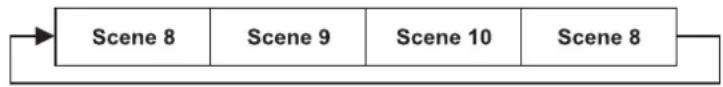
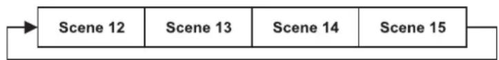
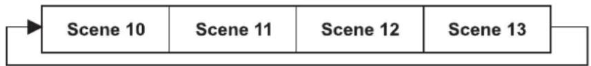
Example:
Program 2 includes scenes: 10, 11, 12, 13;
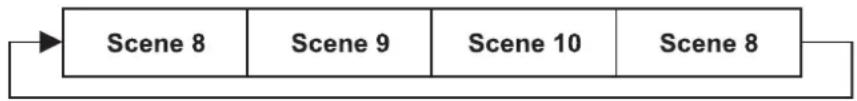
Program 4 includes scenes: 8, 9, 10 and
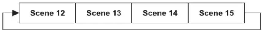
Program 6 includes scenes: 12, 13, 14, 15, 16
Auto Pro Part 1 is Program 2;
Auto Pro Part 2 is Program 3;
Auto Pro Part 3 is Program 6
The 3 Slave groups run the Auto Program in certain time segments, as shown in the following picture:
Part 1:
flowchart
graph LR
    A["Scene 10"] --> B["Scene 11"]
    B --> C["Scene 12"]
    C --> D["Scene 13"]
Part 2:
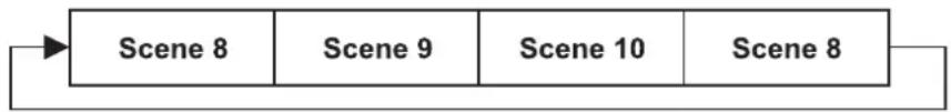
flowchart
graph LR
    A["Scene 8"] --> B["Scene 9"]
    B --> C["Scene 10"]
    C --> D["Scene 8"]
Part 3:
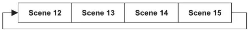
flowchart
graph LR
    A["Scene 12"] --> B["Scene 13"]
    B --> C["Scene 14"]
    C --> D["Scene 15"]
Error Messages
When you turn on the fixture, it will make a reset first. The display may show an error message while there are problems with one or more channels. The error message stands for the channels equipped with a testing sensor.
For example, when the display shows "Color Wheel", it means there is some error in the color wheel channel. If there are some errors on several channels at the same time, you may see the error messages flash repeatedly for 5 times, and then the fixture will generate a reset signal, all the stepper motors will reset. If the error messages maintain after performing reset more than 3 times, it will detect whether the fixture has more than 3 errors. If the fixture has more than 3 errors (including 3 errors), all the channels can not work properly; but if the fixture has less than 3 errors, only the channels which have errors can not work properly, others can work as usual.
The respective error message will appear after the reset of the fixture if the channels magnetic-indexing circuit malfunction (sensor failed or magnet missing) or the stepping-motor is defective (or its driving IC on the main PCB). The channel feature is not located in the default position after the reset.
The different error messages are:
PAN Moving Yellow COLOR GOBO Rotation 2 Stepless zoom
TILT Moving CTO COLOR Prism Strobe
COLOR Wheel Rotation GOBO 1 Prism Rotation Fire wheel
Cyan COLOR GOBO Rotation 1 Focus error
Magenta COLOR Rotation GOBO 2 Iris
CLEANING AND MAINTENANCE
The operator has to make sure that safety-relating and machine-technical installations are inspected by an expert after every four years in the course of an acceptance test.
The operator has to make sure that safety-relating and machine-technical installations are inspected by a skilled person once a year.
The following points have to be considered during the inspection:
1) All screws used for installing the devices or parts of the device have to be tightly connected and must not be corroded.
2) There must not be any deformations on housings, fixations and installation spots (ceiling, suspension, trussing).
3) Mechanically moved parts like axles, eyes and others must not show any traces of wearing (e.g. material abrading or damages) and must not rotate with unbalances.
4) The electric power supply cables must not show any damages, material fatigue (e.g. porous cables) or sediments. Further instructions depending on the installation spot and usage have to be adhered by a skilled installer and any safety problems have to be removed.
DANGER TO LIFE!
Disconnect from mains before starting maintenance operation!
We recommend a frequent cleaning of the device. Please use a moist, lint-free cloth. Never use alcohol or solvents!

CAUTION!
The lens has to be replaced when it is obviously damaged, so that its function is impaired, e. g. due to cracks or deep scratches!
The objective lens will require weekly cleaning as smoke-fluid tends to building up residues, reducing the light-output very quickly. The cooling-fans should be cleaned monthly.
The PHS-1200E is equipped with two dust protection filters inside the projector head. These must be cleaned in six month intervals in order to guarantee perfect air circulation.
Procedure:
Step 1: Unscrew the fixation screws of the housing cover.
Step 2: Remove the housing cover.
Step 3: Remove the dust protection filters and clean them.
Step 4: Replace the dust protection filters in the housing and tighten the fixation screws.
Step 5: Replace the housing cover and tighten the fixation screws.

Do not operate this device with opened cover!
The gobos may be cleaned with a soft brush. The interior of the fixture should be cleaned at least annually using a vacuum-cleaner or an air-jet.
The dichroic colour-filters, the gobo-wheel and the internal lenses should be cleaned monthly.
To ensure a proper function of the gobo-wheel, we recommend lubrication in six month intervals. The quantity of oil must not be excessive in order to avoid that oil runs out when the gobo-wheel rotates.
There are no serviceable parts inside the device except for the lamp and the fuse. Maintenance and service operations are only to be carried out by authorized dealers.
Please refer to the instructions under "Installing/Replacing the lamp".
Replacing the fuse
If the lamp burns out, the fine-wire fuse of the device might fuse, too. Only replace the fuse by a fuse of same type and rating.
Before replacing the fuse, unplug mains lead.
Procedure:
Step 1: Unscrew the fuseholder on the rearpanel with a fitting screwdriver from the housing (anti-clockwise).
Step 2: Remove the old fuse from the fuseholder.
Step 3: Install the new fuse in the fuseholder.
Step 4: Replace the fuseholder in the housing and fix it.
Should you need any spare parts, please use genuine parts.
If the power supply cable of this device becomes damaged, it has to be replaced by authorized dealers only in order to avoid hazards.
Should you have further questions, please contact your dealer.
TECHNICAL SPECIFICATIONS
| Power supply: 230 V AC, 50 Hz ~ | |
| Power consumption: 1300 W | |
| DMX-control-channels: 26 | |
| DMX-512-connection: 5-pin and 3-pin XLR | |
| Flash-rate: 13 Hz | |
| Colour-system: CMY colour-mixture | |
| Colour-wheel: 4 dichroic, correction-filter CTB, | UV-filter + white |
| Colour temperature: 2900 K - 6000 K | |
| Rotating gobo-wheel 1: 5 gobos and open | |
| Rotating gobo-wheel 2: 5 gobos and open | |
| Outside diameter of the gobos: 37.4 mm | |
| Image diameter of the gobos: 31 mm | |
| Maximum PAN-movement 630°: in 3.5 s | |
| Maximum TILT-movement 265°: in 2.5 s | |
| Length of base (including handles): 540 mm | |
| Width of yoke: | 500 mm |
| Height (head horizontal): | 650 mm |
| Weight (net): | 51 kg |
| Maximum ambient temperature T_a : | 45°C |
| Maximum housing temperature T_B (steady state): | 100°C |
| Min.distance from flammable surfaces: | 0.5 m |
| Min.distance to lighted object: | 1 m |
| Fuse: | F 15 A, 250 V + F 2 A, 250 V |
| Accessory: | |
| PHILIPS MSR 1200SA/DE GOLD SFC 10-4 750h | No. 89313015 |
| FUTURELIGHT CP-256/64 controller 16bit | No. 51834288 |
| FUTURELIGHT CP-512/64 controller 16bit | No. 51834295 |
| Wizard-512 USB DMX-Software + Interface | No. 51860102 |
| Wizard-1024 USB DMX-Software + Interface | No. 51860110 |
| FUTURELIGHT UDB 1 USB Update Box | No. 51836901 |
| Flightcase for 1x PHS-1200 incl.reelboard | No. 51836869 |
| Gobo 37,4/31mm glass, design 1 | No. 51845601 |
| Gobo 37,4/31mm glass, design 2 | No. 51845602 |
| Gobo 37,4/31mm glass, design 3 | No. 51845603 |
| Gobo 37,4/31mm glass, design 4 | No. 51845604 |
| Gobo 37,4/31mm glass, design 5 | No. 51845605 |
| Gobo 37,4/31mm glass, design 6 | No. 51845606 |
| Gobo 37,4/31mm glass, design 7 | No. 51845607 |
| Gobo 37,4/31mm glass, design 8 | No. 51845608 |
| Gobo 37,4/31mm glass, design 9 | No. 51845609 |
| Gobo 37,4/31mm glass, design 10 | No. 51845610 |
| Gobo 37,4/31mm glass, design 11 | No. 51845611 |
Please note: Every information is subject to change without prior notice. 24.09.2007 ©
Français
MODE D'EMPLOI
Futurelight®
PHS-1200E
Pro-Head-Spot
ATTENTION!
Moving Head High-Power
natural_image
Line drawing of a mechanical device with no visible text or symbols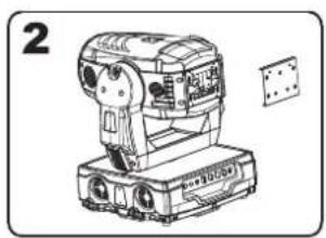
natural_image
Line drawing of a mechanical device with no visible text or symbols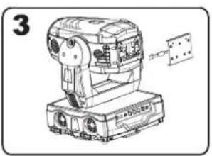
natural_image
Line drawing of a mechanical device with labeled parts (no readable text or symbols)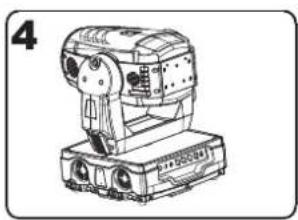
natural_image
Line drawing of a mechanical device with no visible text or symbolsnatural_image
Three hand-drawn diagrams of a food tray with circular cavities, one containing a ring and another with a small hook (no text or symbols)
ATTENTION!
flowchart
graph TD
    A["Lock"] --> B["Un-lock"]
    B --> C["Un-lock"]
    style A fill:#f9f,stroke:#333
    style C fill:#bbf,stroke:#333
Arrêtage PAN:
natural_image
Technical line drawing of a mechanical assembly with three identical components mounted on a truss structure (no text or symbols)natural_image
Technical line drawing of a mechanical device with labeled components (no readable text or symbols)
flowchart
graph LR
    A["Scene 10"] --> B["Scene 11"]
    B --> C["Scene 12"]
    C --> D["Scene 13"]
Part 2:
flowchart
graph LR
    A["Scene 8"] --> B["Scene 9"]
    B --> C["Scene 10"]
    C --> D["Scene 8"]
Part 3:
flowchart
graph LR
    A["Scene 12"] --> B["Scene 13"]
    B --> C["Scene 14"]
    C --> D["Scene 15"]
Français
Moving Head High-Power
natural_image
Line drawing of a mechanical device with no visible text or symbols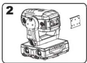
natural_image
Line drawing of a mechanical device with no visible text or symbols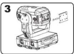
natural_image
Technical line drawing of a mechanical device with no visible text or symbols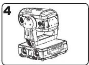
natural_image
Line drawing of a mechanical device with no visible text or symbolsnatural_image
Three hand-drawn diagrams of a food item with circular cavities, arranged in rows (no text or symbols)
Note por favor!
flowchart
graph TD
    A["Lock"] --> B["Un-lock"]
    B --> C["Un-lock"]
    C --> A
Bloqueo PAN:
natural_image
Technical line drawing of a mechanical assembly frame with three identical motors mounted on a truss structure (no text or symbols)natural_image
Technical line drawing of a mechanical device with mounting brackets and labeled parts (no readable text or symbols)(1) Soportes Omega
(2) Ágrafe
(3) Lira de anclaje
(4) Sujetador Quick-Lock
Projector 3
Starting address 53
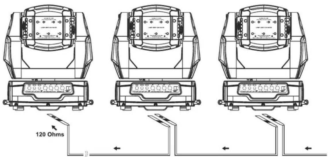
Projector 2
Starting address 27
Projector 1
Starting address 1
DMX-512 Controller

| Scene 10 | Scene 11 | Scene 12 | Scene 13 |
Part 2:
| Scene 8 | Scene 9 | Scene 10 | Scene 8 |
Part 3:
| Scene 12 | Scene 13 | Scene 14 | Scene 15 |