ZHC 950 X - Basket ZANUSSI - Free user manual and instructions
Find the device manual for free ZHC 950 X ZANUSSI in PDF.
Download the instructions for your Basket in PDF format for free! Find your manual ZHC 950 X - ZANUSSI and take your electronic device back in hand. On this page are published all the documents necessary for the use of your device. ZHC 950 X by ZANUSSI.
USER MANUAL ZHC 950 X ZANUSSI
RECOMMENDATIONS AND SUGGESTIONS The Instructions for Use apply to several versions of this appliance. Ac-
cordingly, you may find descriptions of individual features that do not ap-
ply to your specific appliance.
• The manufacturer will not be held liable for any damages resulting from
incorrect or improper installation.
• The minimum safety distance between the cooker top and the extractor
• Check that the mains voltage corresponds to that indicated on the rating
plate fixed to the inside of the hood.
• For Class I appliances, check that the domestic power supply guarantees
Connect the extractor to the exhaust flue through a pipe of minimum di-
ameter 120 mm. The route of the flue must be as short as possible.
• Do not connect the extractor hood to exhaust ducts carrying combustion
fumes (boilers, fireplaces, etc.).
• If the extractor is used in conjunction with non-electrical appliances (e.g.
gas burning appliances), a sufficient degree of aeration must be guaran-
teed in the room in order to prevent the backflow of exhaust gas. The
kitchen must have an opening communicating directly with the open air in
order to guarantee the entry of clean air.
• The extractor hood has been designed exclusively for domestic use to
eliminate kitchen smells.
• Never use the hood for purposes other than for which it has ben designed.
• Never leave high naked flames under the hood when it is in operation.
• Adjust the flame intensity to direct it onto the bottom of the pan only, mak-
ing sure that it does not engulf the sides.
• Deep fat fryers must be continuously monitored during use: overheated oil
can burst into flames.
• Do not flambè under the range hood; risk of fire
• This appliance is not intended for use by persons (including children) with
reduced physical, sensory or mental capabilities, or lack of experience
and knowledge, unless they have been given supervision or instruction
concerning use of the appliance by a person responsible for their safety.
• Children should be supervised to ensure that they do not play with the
• Switch off or unplug the appliance from the mains supply before carrying
out any maintenance work.
• Clean and/or replace the Filters after the specified time period.
• Clean the hood using a damp cloth and a neutral liquid detergent.
Ref. Q.ty Product Components
1 1 Hood Body, complete with: Controls, Light, Blower,
2 1 Telescopic Chimney comprising:
Ref. Q.ty Installation Components
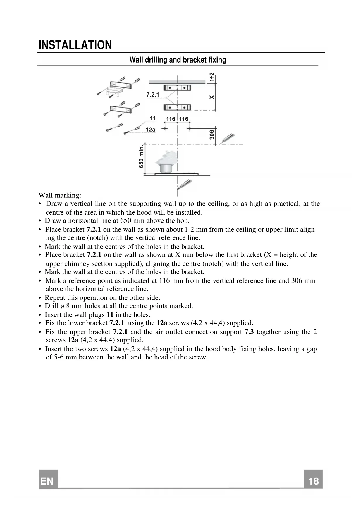
INSTALLATION Wall drilling and bracket fixing
• Draw a vertical line on the supporting wall up to the ceiling, or as high as practical, at the
centre of the area in which the hood will be installed.
• Draw a horizontal line at 650 mm above the hob.
• Place bracket 7.2.1 on the wall as shown about 1-2 mm from the ceiling or upper limit align-
ing the centre (notch) with the vertical reference line.
• Mark the wall at the centres of the holes in the bracket.
• Place bracket 7.2.1 on the wall as shown at X mm below the first bracket (X = height of the
upper chimney section supplied), aligning the centre (notch) with the vertical line.
• Mark the wall at the centres of the holes in the bracket.
• Mark a reference point as indicated at 116 mm from the vertical reference line and 306 mm
above the horizontal reference line.
• Repeat this operation on the other side.
• Drill ø 8 mm holes at all the centre points marked.
• Insert the wall plugs 11 in the holes.
screws 12a (4,2 x 44,4) supplied.
• Insert the two screws 12a (4,2 x 44,4) supplied in the hood body fixing holes, leaving a gap
of 5-6 mm between the wall and the head of the screw.EN
Mounting the hood body
• Before attaching the hood body, tighten the two screws Vr lo-
cated on the hood body mounting points.
• Hook the hood body onto the screws 12a.
• Fully tighten support screws 12a.
• Adjust screws Vr to level the hood body.
DUCTED VERSION AIR EXHAUST SYSTEM When installing the ducted version, connect the hood to the
chimney using either a flexible or rigid pipe ø 150 or 120 mm,
the choice of which is left to the installer.
• To install a ø 120 mm air exhaust connection, insert the re-
ducer flange 9 on the hood body outlet.
• Fix the pipe in position using sufficient pipe clamps (not sup-
• Insert the Connector 15 into the Support bracket 7.3 and fix it
• Insert the connection extension pieces laterally 14.1 in connec-
• Make sure that the outlet of the extension pieces 14.1 is hori-
zontally and vertically aligned with the chimney outlets.
• Connect the air outlet connection 15 to the hood body outlet
using either a flexible or rigid pipe ø 150 mm, the choice of
which is left to the installer.
• Ensure that the activated charcoal filters have been inserted.
ELECTRICAL CONNECTION
• Connect the hood to the mains through a two-pole switch hav-
ing a contact gap of at least 3 mm.
• Remove the grease filters (see paragraph Maintenance) being
sure that the connector of the feeding cable is correctly inserted
in the socket placed on the side of the fan.
• Slightly widen the two sides of the upper flue and hook them
behind the brackets 7.2.1, making sure that they are well
• Secure the sides to the brackets using the 4 screws 12c (2,9 x
• Make sure that the outlet of the extensions pieces is aligned
with the chimney outlets.
• Slightly widen the two sides of the flue and hook them be-
tween the upper flue and the wall, making sure that they are
• Fix the lower part laterally to the hood body using the 2 screws
S L Light Switches the lighting system on and off.
S Led Motor running led.
V1 Motor Switches the extractor motor on and off at low speed. Used to provide a
contin-uos and silent air change in the presence of light cooking vapours.
V2 Speed Medium speed, suitable for most operating conditions given the optimum
treated air flox/noise level ratio.
V3 Intensive Maximum speed, used for eliminating the highest cooking vapour emission,
including long periods.EN
MAINTENANCE Grease filters CLEANING METAL SELF- SUPPORTING GREASE FILTERS • The filters must be cleaned every 2 months of operation, or
more frequently for particularly heavy usage, and can be
washed in a dishwasher.
• Remove the filters one at a time by pushing them towards the
back of the group and pulling down at the same time.
• Wash the filters, taking care not to bend them. Allow them to
dry before refitting.
• When refitting the filters, make sure that the handle is visible
Activated charcoal filter (Recirculation version)
REPLACING THE ACTIVATED CHARCOAL FILTER
• The filter is not washable and cannot be regenerated, and must
be replaced approximately every 4 months of operation, or
more frequently for particularly heavy usage.
• Remove the metal grease filters
• Remove the saturated activated carbon filter by releasing the
• Fit the new filter by hooking it into its seating
40 W incandescent light.
• Remove the metal grease filters.
• Unscrew the bulbs and replace them with new ones having the
same characteristics.
• Replace the metal grease filters.FR
Anschlüss in abluftversion
Ref. Installatieonderdelen
più dettagliate sul riciclaggio di questo prodotto, contattare lufficio comunale, il servizio locale di smaltimento rifiuti o il negozio in cui è stato acquistato il prodotto.
The symbol on the product or on its packaging indicates that this product may not be treated as household waste. Instead it shall be handed over to the applicable
collection point for the recycling of electrical and electronic equipment. By ensuring this product is disposed of correctly, you will help prevent potential negative
consequences for the environment and human health, which could otherwise be caused by inappropriate waste handling of this product. For more detailed information
about recycling of this product, please contact your local city office, your household waste disposal service or the shop where you purchased the product.
Le symbole sur le produit ou son emballage indique que ce produit ne peut être traité comme déchet ménager. Il doit plutôt être remis au point de ramassage