
SMARTRACK - Air Conditioning Tripp Lite - Free user manual and instructions
Find the device manual for free SMARTRACK Tripp Lite in PDF.
| Product Type | Self-Contained Portable Air Conditioner |
| Brand | Tripp Lite |
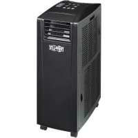
| Model | SMARTRACK (SRCOOL12K) |
| Cooling Capacity | 12,000 BTU (up to 3.4 kW) |
| Refrigerant | Eco-friendly R410A |
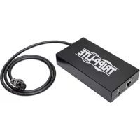
| Power Supply | Grounded AC outlet (voltage per nameplate) |
| Operation Modes | Cooling, dehumidification, fan, silent mode |
| Fan Speeds | High, medium, low, auto |
| Timer | Programmable (on/off) in hourly increments |
| Auto Restart | Yes, after power failure (with 3-minute delay) |
| Thermostat | Adjustable, digital display in °C or °F |
| Air Filters | Two washable filters (evaporator and condenser), cleaning recommended every 2 weeks |
| Condensate Drainage | Auto re-evaporation in cooling mode; manual drain possible in dehumidification mode |
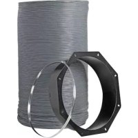
| Flexible Ducts | Exhaust duct (long) and cooling duct (short), max length 300 cm |
| Adjustable Exhaust Panel | For window or drop ceiling, adjustable width from 67.5 to 125 cm |
| Full Tank Alarm | E4 code display and auto shut-off |
| Protection | Fuse/circuit breaker, compressor 3-minute delay, shut-off on full tank |
| Maintenance | Clean filters with warm water (max 40°C) without harsh detergent; wipe body with dry cloth |
| Included Parts | Ducts (exhaust and cooling), adapters, exhaust panel, screws, drain plugs |
| Repairability | Limited 1-year warranty; technical support and returns via www.tripplite.com |
| Recommended Applications | Cooling server racks, IT equipment hot spots, small rooms |
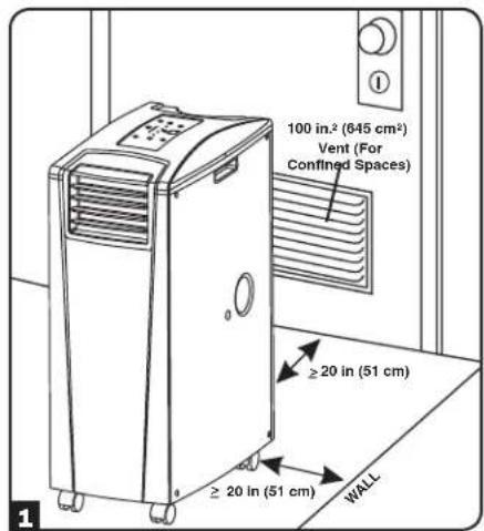
| Required Clearance | At least 51 cm (20 in) from walls at rear and sides |
Frequently Asked Questions - SMARTRACK Tripp Lite
User questions about SMARTRACK Tripp Lite
0 question about this device. Answer the ones you know or ask your own.
Ask a new question about this device
Download the instructions for your Air Conditioning in PDF format for free! Find your manual SMARTRACK - Tripp Lite and take your electronic device back in hand. On this page are published all the documents necessary for the use of your device. SMARTRACK by Tripp Lite.
USER MANUAL SMARTRACK Tripp Lite
Portable Air Conditioning Unit
SRCOOL12K (120V, 60Hz) SRXCOOL12K (230V, 50 Hz)

Introduction 2
Important Safety Instructions 2
Features 3
Installation 4
Operation 8
Maintenance 9
Troubleshooting 9
Storage & Service 10
Warranty & Warranty Registration 10
Espanol 11
Français 21
Pycckn 31


1111 W. 35th Street, Chicago, IL 60609 USA • www.triplite.com/support
Copyright © 2013 Tripp Lite.
Introduction
The self-contained Portable Air Conditioning Unit provides 12,000 BTU (up to 3.4kW ) of supplemental cooling capacity. Designed for IT environments, it's ideal for cooling overheated rack enclosures, IT equipment hot spots and network closets without access to facility air conditioning. The Portable Air Conditioning Unit can focus cool air through its flexible cooling duct or cool a small room through its louvered vent. It also filters and dehumidifies air to improve operating conditions and equipment reliability. Condensate is re-evaporated for drip-free operation, so you won't waste time emptying water collection tanks. The self-contained design does not require any plumbing or special circuits, so setup is quick and easy. Eco-friendly R410A refrigerant meets environmental standards worldwide.
Recommended Applications:
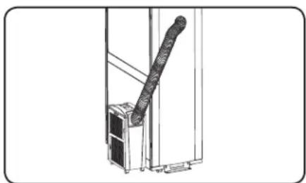
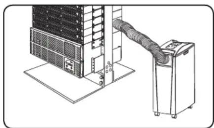
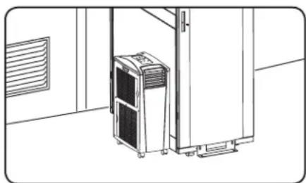
1. Cooling an overheated rack enclosure.
2. Cooling an equipment hot spot inside or outside a rack enclosure.
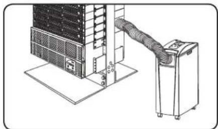
3. Cooling a small room.
Important Safety Instructions

SAVE THESE INSTRUCTIONS
This manual contains instructions and warnings that should be followed during the installation, operation and storage of this product. Failure to heed these warnings may affect your warranty.
Warnings
The individual user should determine prior to use whether this device is suitable, adequate or safe for the use intended. Since individual applications are subject to great variation, the manufacturer makes no representation or warranty as to the suitability or fitness of this device for any specific application.
- Install the unit indoors, away from extreme temperatures or humidity, direct sunlight, dust and conductive contaminants.
- Leave adequate space around the unit for ventilation, with rear and vented sides not less than 20 inches (51 cm) from walls or other obstacles.
Install the unit on a flat surface with a gradient no more than 10^
- Connect the unit directly to a grounded AC power outlet. Failure to do so may cause an electric shock or fire.
- The power supply for the unit must be rated in accordance with the unit's nameplate.
- Do not modify the plug nor use an adapter that would eliminate the ground connection.
- Do not use an extension cord to connect the unit to an AC outlet. Use only the power cord that came with the unit.
Comply with all applicable wiring and safety regulations, such as National Electrical Code (NEC) in the United States.
- Do not plug additional equipment into the outlet where the unit is plugged in. Overloading the outlet may cause an electric shock or fire.
- Do not attempt to turn the unit on or off by connecting or disconnecting the AC plug. A serious electric shock may occur. Use the ON/OFF button to turn the unit on or off.
- Turn the unit off and unplug it from the AC outlet before performing maintenance.
- Before connecting the unit to a dedicated drainage system, turn it off and unplug it. There is a risk of electric shock while the unit is plugged in.
- Maintenance should be performed by trained personnel only.
- Do not use thinners, alcohol, detergents or abrasive brushes to clean the unit's cabinet. These items may damage the cabinet.
- Do not pour water over the unit. This may cause an electric shock and damage the unit.
- Do not operate the unit without the air filter. This may cause dust accumulation that may damage the unit.
Do not attempt to operate the unit in a room with inadequate air circulation. Provide makeup air in accordance with applicable building codes.
- Do not place objects on top of the unit.
- Use of this equipment in life support applications where failure of this equipment can reasonably be expected to cause the failure of the life support equipment or to significantly affect its safety or effectiveness is not recommended. Do not use this equipment in the presence of a flammable anesthetic mixture with air, oxygen or nitrous oxide.
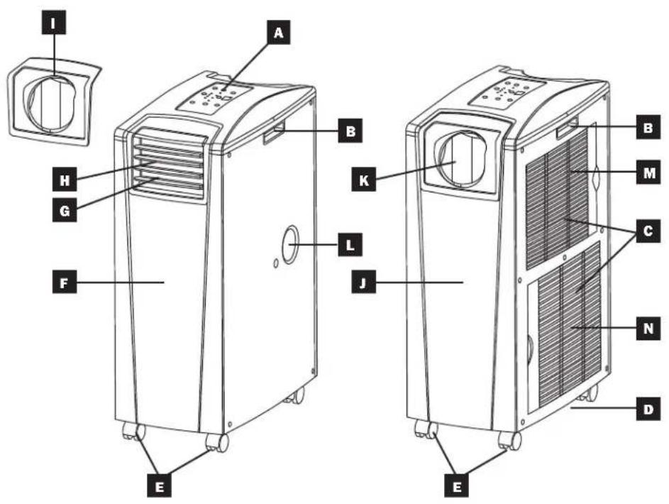
Features
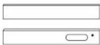
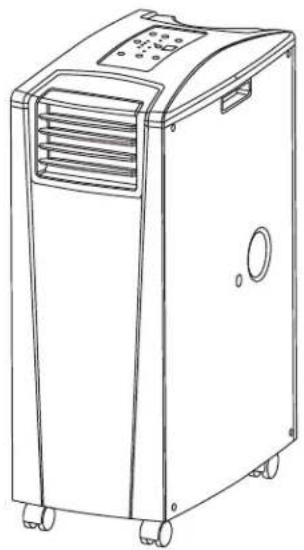
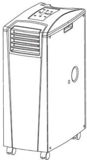
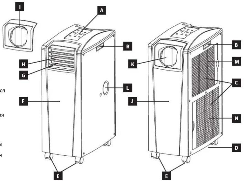
Front View
A Control Panel
B Recessed Handles
Air Filter Covers
Drainage Outlet
E Casters
F Front Panel
Cool Air Output
H Louvered Vent Insert (Pre-Installed)
Cooling Duct Adapter (Optional)
Rear Panel
K Warm Air Exhaust
Evaporator Drainage Outlet
M Evaporator Filter
N Condenser Filter
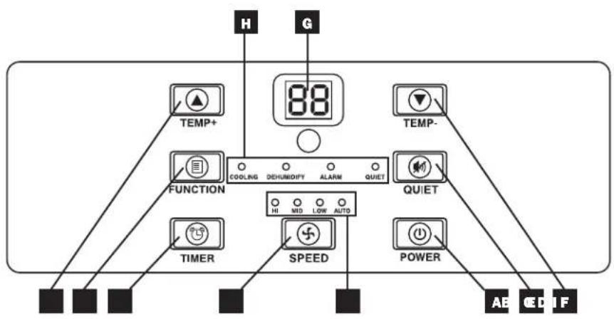
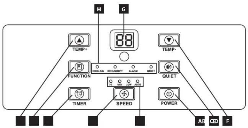
Control Panel
A "POWER" Button
B FUNCTION"Button
C "TIMER" Button
D "FAN SPEED" Button
E“QUIET”Button
F Temperature Control Buttons
Numeric Display
H Operating Mode LEDs
Fan Speed Mode LEDs
Installation
Warning: After removing the unit from the shipping container, check for damage or missing parts. (Refer to the parts list below.) If you notice a problem, visit www.triplite.com/support for service. Do not attempt to operate a damaged unit.
Accessory Parts List:
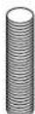
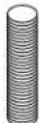
Exhaust Duct (Longer Tube)

Cooling Duct (Shorter Tube)
Exhaust Duct Adapter
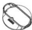
Adjustable Exhaust Panel (2 Sections)

Self-Tapping Screw
2 Duct Adapters (1 Pre-Installed)
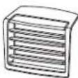
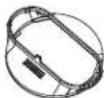
Louvered Vent Insert (Pre-Installed)
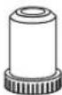
Drainage Plug (2 Pre-Installed)
Unit Placement
Place the unit on a flat, level surface near a grounded AC outlet rated in accordance with the unit nameplate (90-110% of specified voltage). Leave adequate space around the unit for ventilation, with rear and vented sides not less than 20 inches (51 cm) from walls or other obstacles. Place the unit in a location with convenient access to a drop ceiling or window to provide the straightest, shortest path available for the flexible exhaust duct. If you plan to use the flexible cooling duct to focus cool air on a specific rack enclosure or device, place the unit near the targeted rack enclosure or device to provide the straightest, shortest path available for the cooling duct.
Warning: Do not use an extension cord to connect the unit to an AC outlet. Use only the power cord that came with the unit.
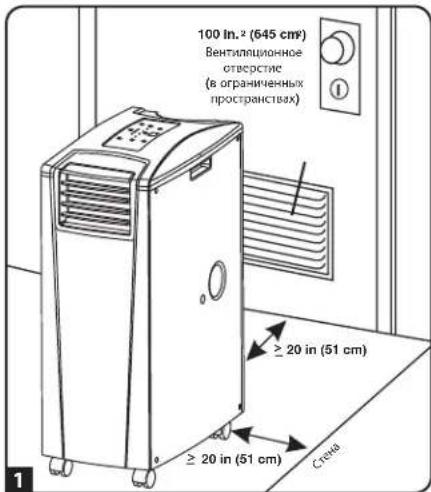
Note: If the unit will operate in a confined space (such as closet), you must supply makeup air in order to maintain airflow efficiency. A 100 in.² (645 cm²) or larger vent installed near the bottom of the door should supply adequate makeup air for a typical closet. Consult applicable building codes for more information.
Exhaust hose not shown—see Section 3.
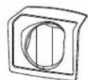
2 Cooling Duct Connection (Optional)
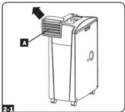
The pre-installed louvered vent insert is appropriate for room cooling applications. If you plan to cool a room, skip step 2 and proceed to step 3. If you plan to use the flexible cooling duct to focus cool air on a specific device or rack enclosure, follow the instructions below.
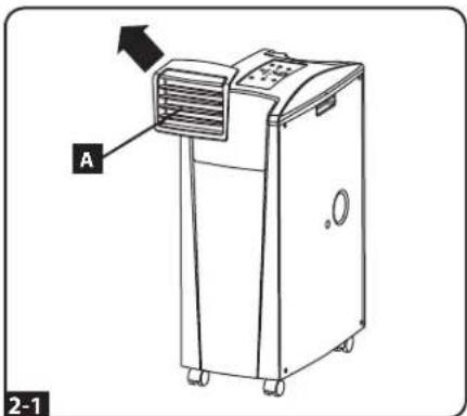
21 Remove the louvered vent insert by pulling it outward and upward.
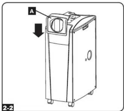
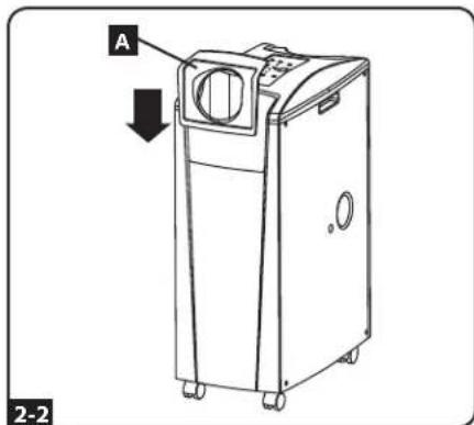
Align the cooling duct adapter in the vent opening and push it downward until it snaps into place.
Installation (continued)
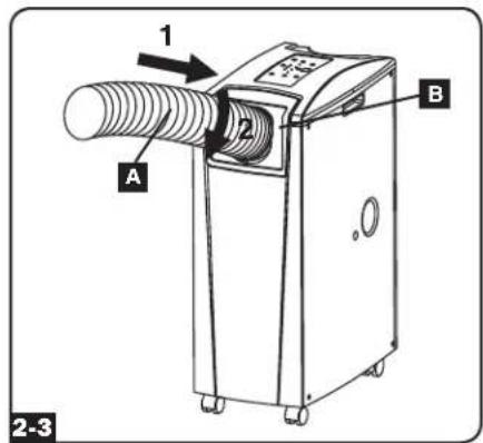
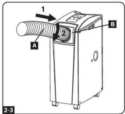
2-3 Connect the flexible cooling duct (shorter tube A) to the cooling duct adapter B. Align the duct with the circular adapter opening, push the duct downward and turn the duct clockwise until it screws into the adapter solidly.
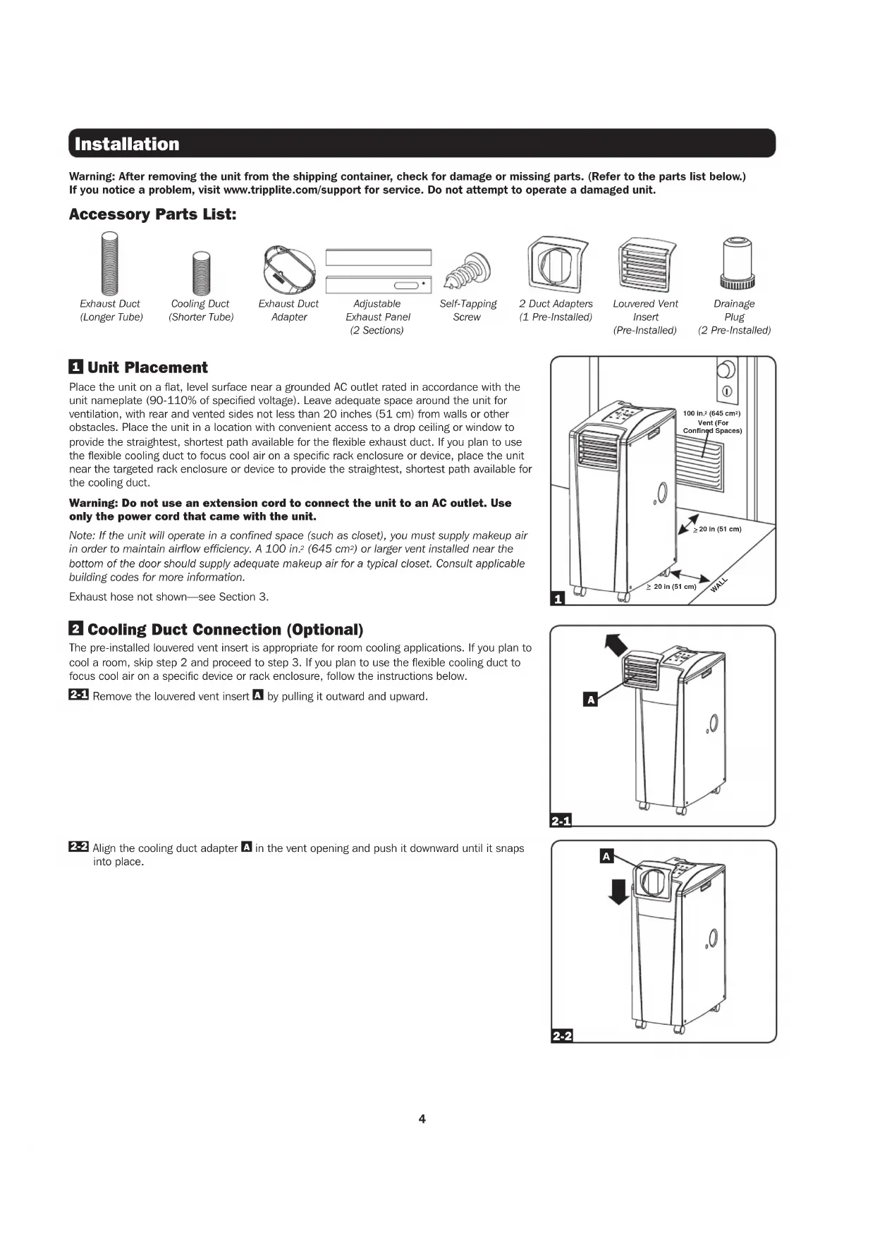
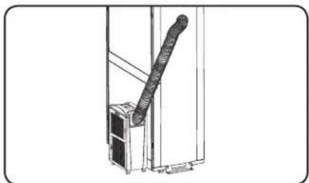
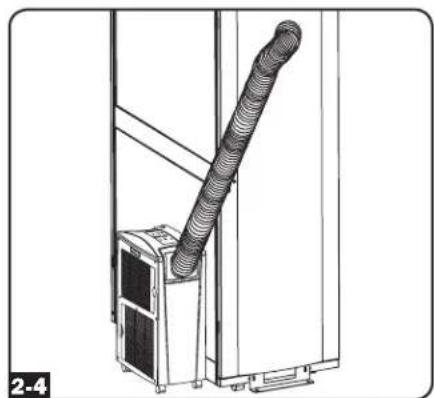
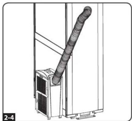
2-4 Place the other end of the cooling duct near the air intake of the target device or rack enclosure, using the straightest, shortest path available. If you plan to cool a rack enclosure, place the end of the cooling duct over a perforated area near the top of the enclosure's front door (or near the top of the bank of equipment that requires cooling). Cool air will sink and spread across the air intakes at the front of the rack enclosure.
3 Exhaust Duct Connection
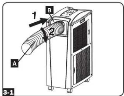
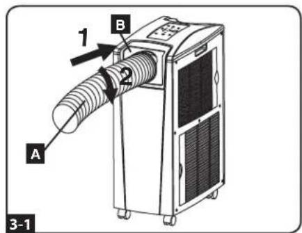
3-1 Connect the flexible exhaust duct (longer tube A) to the warm air exhaust vent on the rear panel of the unit B. Align the duct with the circular vent opening, push the duct inward and turn the duct clockwise until it screws into the exhaust vent solidly.
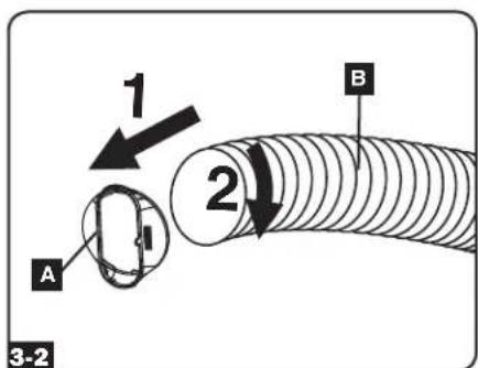
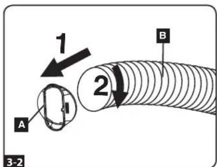
3-2 Connect the other end of the exhaust duct A to the exhaust duct adapter B. Align the duct with the circular adapter opening, push the duct inward and turn the duct clockwise until it screws into the adapter solidly.
If you plan to connect the exhaust duct to a drop ceiling, proceed to step 4. If you plan to connect the exhaust duct to a window, proceed to step 5.
Installation (continued)
4 Drop Ceiling Exhaust Connection
Warning: Some ceilings may require modified installation procedures. The user must determine the fitness of hardware and procedures before installing. The procedures described in this manual may not be appropriate for all applications.
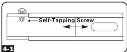
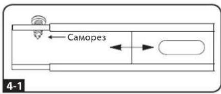
4-1 Choose a removable drop ceiling panel near the unit to provide the straightest, shortest path available for the flexible exhaust duct. Measure the width of the ceiling panel, including the portion that rests on the ceiling grid. Combine the two sections of the adjustable exhaust panel, then adjust the exhaust panel to match the width of the ceiling panel. After the exhaust panel is set to the correct width, use the included self-tapping screw to lock it in place. Note: The exhaust panel can adjust from 26.6 to 49.2 inches (67.5 to 125 cm).
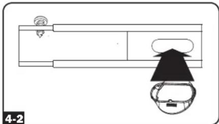
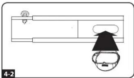
4-2 Insert the exhaust duct adapter into the oblong hole in the adjustable exhaust panel. The adapter will snap into place.
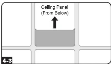
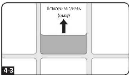
4-3 Slide the ceiling panel out of the way and place the exhaust panel inside the ceiling space. Allow the exhaust panel to rest on top of the ceiling grid. Note: There must be at least 10 inches (25.4 cm) of open space above the exhaust panel to allow adequate airflow.
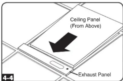
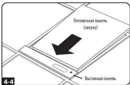
4-4 Slide the ceiling panel back into place so that it adjoins the exhaust panel and closes any gaps in the ceiling. A tight seal will permit maximum cooling efficiency. If the installation is permanent, trim the ceiling panel so it doesn't overlap the ceiling grid.
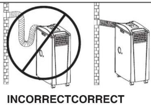
Note: The flexible exhaust duct can extend to a maximum length of 118 inches (300 cm). Provide the straightest, shortest path available. Excessive bending or stretching of the duct will reduce cooling efficiency.
After completing step 4, proceed to step 6.
5 Window Exhaust Connection
Warning: Some windows may require modified installation procedures. The user must determine the fitness of hardware and procedures before installing. The procedures described in this manual may not be appropriate for all applications.
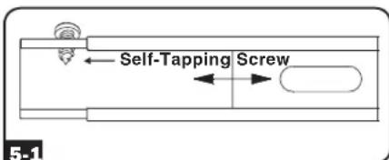
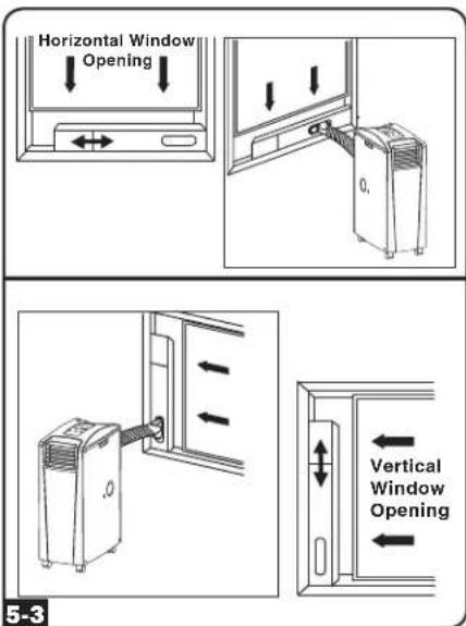
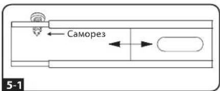
5.1 Measure the window opening. Combine the two sections of the adjustable exhaust panel, then adjust the exhaust panel to match the width of the window opening. After the exhaust panel is set to the correct width, use the included self-tapping screw to lock it in place. Note: The exhaust panel can adjust from 26.6 to 49.2 inches (67.5 to 125 cm). It is compatible with vertical and horizontal mounting.
5-2 Insert the exhaust duct adapter into the oblong hole in the adjustable exhaust panel. The adapter will snap into place.
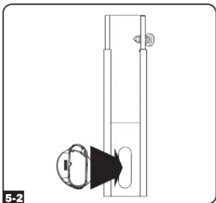
Installation (continued)
5-3 Insert the exhaust panel into the window opening, then close the window against the exhaust panel. A tight seal will permit maximum cooling efficiency. Note: There must be at least 10 inches (25.4 cm) of open space behind the exhaust panel to allow adequate airflow.
Note: The flexible exhaust duct can extend to a maximum length of 118 inches (300 cm). Provide the straightest, shortest path available. Excessive bending or stretching of the duct will reduce cooling efficiency.
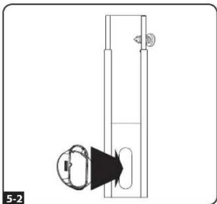
6 Drainage Plug Insertion
Warning: The unit's built-in re-evaporator will not function until you insert the drainage plug into the drainage outlet.
When the unit cools or dehumidifies, condensation forms. The unit has a built-in re-evaporator that allows it to expel condensation through the warm air exhaust stream. This feature allows the unit to operate indefinitely without requiring you to empty a water collection tank. The unit ships with both the upper and lower drainage plugs pre-installed.
Cooling Mode with Re-Evaporation
Both plugs must remain installed to enable re-evaporation of condensation.
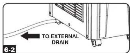
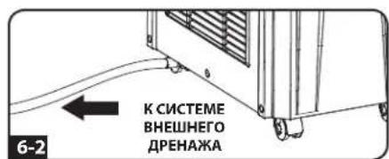
Cooling Mode without Re-Evaporation
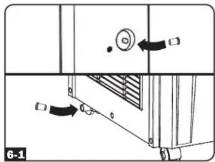
To use Cooling mode without re-evaporating condensation, remove the bottom drain plug and route user-supplied drain line to external drainage. The top drain plug must remain installed.
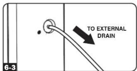
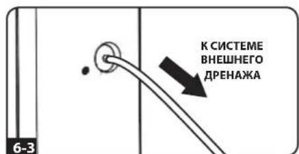
6-3 Dehumidify Mode
When using the unit in Dehumidify mode, remove the top drain plug and route user-supplied drain line to external drainage. The bottom drain must remain installed. This will maximize the amount of water removed from the air.
Note: If the drainage system becomes clogged, a small internal reservoir will collect condensation. If the drainage system is not cleared before the internal reservoir fills, the unit will shut down automatically.
Warning: Before connecting the unit to a dedicated drainage system, turn it off and unplug it. There is a risk of electric shock while the unit is plugged in.
Note: If your building's cooling system has night or weekend thermostat setbacks, has periodic shutdowns, or has limited cooling capacity, you may need to consider alternatives to the standard installation. This product is meant to be used as a supplemental cooling device, and cannot make up for significant fluctuations in building temperature or humidity.
Low Temperature Operation
The SRCOOL12K is a high performance cooler, capable of producing very cold air output. When using the SRCOOL12K in environments that are already cold (20^ / 68^ or less), Tripp Lite recommends using the Dehumidify Mode only. This will allow the unit to continue to provide the supplemental cooling while preventing any evaporator icing issues caused by the low room temperature.
Operation
Warning: Install the unit according to the instructions in the "Installation" section before attempting to operate it.
Power
Turn the unit on or off by pressing the "POWER" button.
The unit has a three-minute compressor delay in order to prevent potential circuit overloads at start up.
Automatic Restart Feature
The unit will turn on and resume operation automatically when power is restored after a power outage. The unit will use the same settings that it used immediately before the power outage occurred. Note: If the power outage is brief, the unit will run the fan alone for three minutes before resuming normal operation. The delay allows the compressor to depressurize so the unit will function properly when it enters Cool mode.
Cool Mode
Pressing the "FUNCTION" button cycles between Cool mode and Dehumidify mode. The "COOLING" LED illuminates when Cool mode is active.
Press the TEMP + and TEMP- buttons to set the temperature in Cool mode. The selected temperature is shown on the numeric display. Once set, the desired temperature will blink five times after which the display will show the current room temperature.
Press the "FAN SPEED" button to cycle between high, medium and low fan speeds. An LED illuminates to indicate the selected fan speed. When speed is set on AUTO, the unit will automatically select a fan speed based on the set and ambient temperatures. If ambient temperature is lower than the set temperature, the fan will run and the "COOLING" LED will blink to indicate that the compressor is off. When cooling resumes, the "COOLING" LED will remain illuminated.


Dehumidify Mode
Pressing the "FUNCTION" button cycles between Cool mode and Dehumidify mode.
The "DEHUMIDIFY" LED illuminates when Dehumidify mode is active. In Dehumidify mode, the fan runs at a fixed speed and temperature controls are irrelevant. For optimal performance in Dehumidify mode, close windows and doors, remove the top drain plug and route user-supplied drain line to external drainage.


Timer
The "TIMER" button allows you to schedule the unit to turn on or off automatically.
Timer On (Note: The unit must be off to activate the Timer On function. Confirm that mode, temperature and fan speed settings are correct before activating the Timer On function.) Activate the timer by pressing the "TIMER" button. Press the TEMP+ and TEMP- buttons to set the delay (in hours) before the unit will turn on. The number of hours is shown on the numeric display. The number will flash on the screen five times before returning to the current temperature.
Timer Off (Note: The unit must be on to activate the Timer Off function.) Activate the timer by pressing the "TIMER" button. Press the TEMP+ and TEMP- buttons to set the delay (in hours) before the unit will turn off. The number of hours is shown on the numeric display. The number will flash on the screen five times before returning to the current temperature.

Quiet Control Mode
The unit includes a Quiet Control mode which regulates the cooling via the timer and microprocessor to achieve quieter operation levels when noise is an issue.
To activate, press the "QUIET" button. The Quiet LED will turn on. Set the desired temperature and then set the timer to the duration of the Quiet Control mode cycle. During the course of the cycle, the microprocessor memory will adjust the preset temperature by 0.9^ (0.5^) every 30 minutes until it reaches the desired temperature. Once the temperature is reached, the unit will maintain the temperature for the duration of the set time.


Changing Degree Units
The unit can display temperature in both Celsius and Fahrenheit. The default setting for the SRCOOL12K is Fahrenheit and the SRXCOOL12K is Celsius.
To toggle between temperature modes, put the unit in standby mode. The air conditioner is in standby mode when it is plugged into live AC power, but powered off. Then, hold the "FUNCTION" key for 10 seconds until a beep sounds.

Operation (continued)
Alarm
When the water tank is full, the unit will display the message "E4" on its screen. To resume normal function, turn the unit off, remove the drainage plug and drain the excess water from the unit. Replace the plug and turn the unit on to begin cooling.
O ALARM
Maintenance
Periodic maintenance extends the unit's lifespan and permits maximum operating efficiency.
Cleaning the Air Filters
It is important to keep the air filters clean and free of dust. When the filters are dirty or clogged with dust, it decreases cooling efficiency and can threaten air quality. Tripp Lite recommends cleaning the filters at least once every two weeks.

Before cleaning the filters, turn the unit off and unplug it! There is a risk of electric shock while the unit is plugged in.
- Turn the unit off and unplug it.
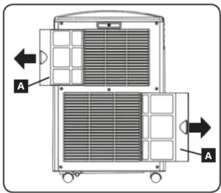
- Remove the filters A by sliding them out of the cabinet.
- Wash the filters in warm water with a neutral detergent. Do not put the filters into a dishwasher or use harsh detergents or chemicals. Allow the filters to air dry completely after washing. Note: Do not use water hotter than 104^ (40^) to clean the filters.
- Replace the filters by sliding them back into their original position.
- Plug the unit in and resume normal operation.
Cleaning the Cabinet

Before cleaning the cabinet, turn the unit off and unplug it! There is a risk of electric shock while the unit is plugged in.
- Turn the unit off and unplug it.
- Wipe the unit with a dry, non-abrasive cloth. Do not use gasoline, benzene, thinners or other harsh chemicals that may damage the surface. Do not pour water directly over the unit or into the working parts. This causes a risk of electrical shock and deterioration of electrical components and wiring insulation.
- In extreme cases, wipe the unit with a damp cloth to remove residue.
Troubleshooting
Review the possible solutions below. If the problem persists, please visit www.triplite.com/support for service.
| Problem Possible Cause Possible Solution | ||
| The unit does not function. | The unit is turned off. | Turn the unit on. (See "Operation" section.) |
| The unit is not plugged in. Plug the unit into a suitable outlet. | ||
| Main power is off. Check fuses or circuit breaker. | ||
| Cooling performance is unsatisfactory. | The air exhaust or intake is blocked. | Confirm that all ducts and intakes are clear of obstructions. |
| The temperature setting is too high. Adjust the temperature setting. | ||
| The fan speed setting is too low. Adjust the fan setting. | ||
| The air filters are dirty. Clean the air filters. | ||
| The wattage of the rack enclosure, the size of the room or the ambient temperature exceeds the cooling capacity of a single unit. | Install additional units or contact Tripp Lite for additional cooling solutions suitable for your application. | |
| The unit leaks water. | The drainage plug is not installed. | Insert the drainage plug in the drainage outlet. (See "Installation" section.) |
| The unit generates excessive noise or vibration. | The unit is on an uneven or unstable surface. | Move the unit to a level, stable surface. |
| The unit has ice or frost buildup. | The unit is operating in an environment with excess humidity. | OPTION 1: Turn off the unit, and let the unit defrost. Once defrosted, ensure the unit is operating with the fan speed set on HIGH. OPTION 2: Turn off the unit, and let the unit defrost. Once defrosted, operate the unit in DEHUMIDIFY MODE, or increase the desired temperature setpoint. |
Troubleshooting (continued)
Additional Display Error Codes
The Tripp Lite SRC00L12K has the ability to continually monitor itself. Should an error occur, the display will show one of 5 error codes below:
| Error Code Description | |
| E0 Internal Communication Error | |
| E1 Indoor Temperature Sensor Error | |
| E2 Internal Temperature Sensor Error | |
| E3 Refrigerant Error | |
| E4 Water Full | |
Code E4 can be cleared by emptying the water tank. Consult the owner's manual for details.
For Codes E0, E1, E2, and E3 follow these steps:
- Power cycle the unit by unplugging it from the source for 5 minutes.
- Plug the unit back in.
- Restart the unit.
If the code remains clear, continue to operate the unit as normal. If the code returns, please contact Tripp Lite for further instructions.
Storage and Service
Storage
Before storing the unit, confirm that the ducts and vents are secured or removed and cared for properly. Also confirm that the unit is drained of condensation.
Service
Your Tripp Lite product is covered by the warranty described in this manual. A variety of Extended Warranty and On-Site Service Programs are also available from Tripp Lite. For more information on service, visit www.triplite.com/support. Before returning your product for service, follow these steps:
- Review the installation and operation procedures in this manual to insure that the service problem does not originate from a misreading of the instructions.
- If the problem continues, do not contact or return the product to the dealer. Instead, visit www.triplite.com/support.
- If the problem requires service, visit www.triplite.com/support and click the Product Returns link. From here you can request a Returned Material Authorization (RMA) number, which is required for service. This simple on-line form will ask for your unit's model and serial numbers, along with other general purchaser information. The RMA number, along with shipping instructions will be emailed to you. Any damages (direct, indirect, special or consequential) to the product incurred during shipment to Tripp Lite or an authorized Tripp Lite service center is not covered under warranty. Products shipped to Tripp Lite or an authorized Tripp Lite service center must have transportation charges prepaid. Mark the RMA number on the outside of the package. If the product is within its warranty period, enclose a copy of your sales receipt. Return the product for service using an insured carrier to the address given to you when you request the RMA.
Warranty and Warranty Registration
Warranty
1-YEAR LIMITED WARRANTY
Sell warrants this product, if used in accordance with all applicable instructions, to be free from original defects in material and workmanship for a period of 1 year from the date of initial purchase. If the product should prove defective in material or workmanship within that period, Seller will repair or replace the product, in its sole discretion. Service under this Warranty can only be obtained by your delivering or shipping the product (with all shipping or delivery charges prepaid) to: Tripp Lite, 1111 W. 35th Street, Chicago, IL 60609 USA. Seller will pay return shipping charges.
THIS WARRANTY DOES NOT APPLY TO NORMAL WEAR OR TO DAMAGE RESULTING FROM ACCIDENT, MISUSE, ABUSE OR NEGLECT. SELLER MAKES NO EXPRESS WARRANTY OTHER THAN THE WARRANTY EXPRESSLY SET FORTH HEREIN. EXCEPT TO THE EXTENT PROHIBITED BY APPLICABLE LAW, ALL IMPLIED WARRANTY, INCLUDING ALL WARRANTY OF MERCHANTABILITY OR FITNESS, ARE LIMITED IN DURATION TO THE WARRANTY PERIOD SET FORTH ABOVE; AND THIS WARRANTY EXPRESSLY EXCUSES ALL INCIDENTAL AND CONSEQUENTIAL DAMAGES. (Some states do not allow limitations on how long an implied warranty lasts, and some states do not allow the exclusion or limitation of incidental or consequential damages, so the above limitations or exclusions may not apply to you. This Warranty gives you specific legal rights, and you may have other rights which vary from jurisdiction to jurisdiction).
WARNING: The individual user should determine prior to use whether this device is suitable, adequate or safe for the use intended. Since individual applications are subject to great variation, the manufacturer makes no representation or warranty as to the suitability or fitness of this device for any specific application.
WARRANTY REGISTRATION
Visit www.triplite.com/warranty today to register the warranty for your new Tripp Lite product. You'll be automatically entered into a drawing for a chance to win a FREE Tripp Lite product!
- No purchase necessary. Void where prohibited. Some restrictions apply. Open to U.S. residents only. See www.tripplite.com for details.
Regulatory Compliance Identification Numbers
For the purpose of regulatory compliance certifications and identification, your Tripp Lite product has been assigned a unique series number. The series number can be found on the product nameplate label, along with all required approval markings and information. When requesting compliance information for this product, always refer to the series number. The series number should not be confused with the marking name or model number of the product.

WEEE Compliance Information for Tripp Lite Customers and Recyclers (European Union)
Note: This statement applies to products marked with the WEEE logo.
Under the Waste Electrical and Electronic Equipment (WEEE) Directive and implementing regulations, when customers buy new electrical and electronic equipment from Tripp Life they are
entitled to:
- Send old equipment for recycling on a one-for-one, like-for-like basis (this varies depending on the country)
- Send the new equipment back for recycling when this ultimately becomes waste
Tripp Lite has a policy of continuous improvement. Product specifications are subject to change without notice.


1111 W. 35th Street, Chicago, IL 60609 USA • www.triplite.com/support
SRCOOL12K (120V, 60 Hz)
SRXCOOL12K (230V, 50 Hz)

Introduccion 12
1111 W. 35th Street, Chicago, IL 60609 USA • www.triplite.com/support
Copyright © 2013 Tripp Lite.
Introduccion
Operation (continued)
Alarma
1111 W. 35th Street, Chicago, IL 60609 USA www.triplite.com/support
SRCOOL12K (120 V, 60 Hz)
SRXCOOL12K (230V, 50 Hz)
Introduction 22
1111 W. 35th Street, Chicago, IL 60609 USA • www.triplite.com/support
Copyright © 2013 Tripp Lite.
Introduction
Installation (suite)
Installation (suite)
5 Window Exhaust Connection
Installation (suite)
Operation (continued)
T t t d Tripp Lle is s a
1111 W. 35th Street, Chicago, IL 60609 USA
www.triplite.com/support
PykoBoDCTBO NOIb3OBaTeJa
Ipehenochoi 6lOK KOHdNcNoHnpOBaHnA
SRCOOL12K (120 B, 60 Γι) SRXCOOL12K (230 B, 50 Γι)
BVeJeHne 32
Baxkhble npabnla TexHnK6e3oNaChoctn 32
IeTaII n 33
yctaHOBka 34
38
TexHmueeckoe 6cbnyxnbHne 39
BbIaBHeHne uYcTaPaeHne HEnCnPaBHoTei 40
XpaHeHne n 06cnyKuBaHne 40
IapaHTnHbIe 68a3aTeNbCTBa n perncTpaunra paHTn 40
English 1
Espanol 11
Français 21


1111 W. 35th Street, Chicago, IL 60609 USA • www.triplite.com/support Copyright © 2013 Tripp Lite.
BVeDHeHne
AToHOMHoe nepeHOChoe yCTPOIcTBO KOHNIOHINOBAHn BO3dyxA o6eCneuHaBt IOnONHInTebHyO xoNODonPn3BOaNTbHocB b pa3Mepe 12000BTU (do 3,4KbT). 3TO YCTPOIcTB0, PpEHa3NaueHHOE dIpaobToB V NT-cpeAx, IqealbHO IOXoDIT dIra OXaJxDEHn pepeBaouxxC KOpyncbx cToek, MeCT NLOTHORO p3MaeeHn IV-OBOpyDOBAHn n CteBbIX y3IOB, PaCNOJooEHhBx BHE 3ObI DeiCTBn CImCTeMbI CEHTpaBnHO KOHNIOHINOBAHn OBekTa. 3TOT nepeHOCH KOHNIOHep CNOCoEB npOBDnB KOHePTnpOBAHhIE NOTOKn XOLOHOrO BO3dyxA uee3 CBW n6kN kAnai OXaJxDEHn INN OXaKDaTb He6oBuHn OmeJeHne, HapabnI XoNODhB BO3dyX uee3 CBoE bByOXHOe TOpBCTNe CKaJIIO3NbIMn 3aCIOHkAMn. Kpome TorO, OH o6CeNEuBAET fNtBTPaunIO uOcyHeHn BO3dyxA, YTO CNoCo6bCTByE tYnyuWeHIO yCObn PAoBtI O6OpyOBAHn I NobSeHn Ero NaedKHOCTN. O6pa3yoUnsCA KOHeHcAT NOBTOPH NoPapReTc, YTO NCKIOUaET BO3MOXHOCTb NODKeHAN I N03BOaHET He TpAITb BpEMHa N OPOOxHEmKoCTe I Da c60pa BoDi. AToHOHMn KOHCTpyKUN He Tpe6yET NODKnUeHn K BOOIpOBoDY, KaHJIINaUIN INI CneuaNBHIM CetTAM, YTO YCKOPAE T IOpeCC hauJIbHOYCTAHOBKn. 3KoJIoNueckn UcTbI XJaDARETH R410A COOTBeTcBByET Tpe6oBaHnM MExdhyapodHBx npPiPOOOxPAHbIX CTahdaptOB.
Pekomehdyemble uei npimHeHHa:
1. OxnaKeHne nepepeBaOuixxKoPnyChbIX CToeK.
2. OxnaJaeHne MeT nIOTHO r a3MeueHn ITO6OpyOBoAHn BHyTpIn n ChapyKn KOpnyCHOI CTOnKtN.
3. OxjcknHe He6oBbOTo nomeeHna
Baxhblye yka3aHnno ToxHnke 6e30nacHOCTn

COXPAHNTE HACTOJIUE YKA3AHNA
B hactoem pykoobocbe coepkatayka3aHn n npdynpexdeHn, KOtOpbie Heo6xmo co6nOaTb B npoucece yctahOBKn, kcnnyataun xpaHnna daHHoro n3den. NrhopnpobAHne 3TNx npdynpexdeHn moKet npnbectn K notepe Baewr rapantnn.
PpeynpekdeHna
IpeednauonmncnoB0aHnnaDaHoro yctpoiCTBa nlo3oBaTeBdoJxHye6yBeiNbCBA TOM,TOOHOABJIeTcPnproDhbIM,COTBETCTBYUcIMMN 63oNaChbIMnnpdionoraemoripnpmeHHeCBsNCbohImpa3HoOp4zHMeKOHKePTbIX npimHeHHpOn3BOuTeB He Daet KAKHX-N60 3abeepnHnrapaHTN OTHocntEBo npiroDHOCTNaHHO mDeJeINra KaKOro-N60 KOHKpeTHorO npimeHeHHn Nn erOcoBTcTBnKaKM-M60 KOHKpeThbM Tpe6oHaHnM.
- DaaHoe yctpoiCTBO dOJIxHO 6bIb yCTaHOBJeHO B3akpIOM NOMEUeHN I 3aUuEeHO OT BO3dEICTBnA KcTpeMaIbHbIX TempeATy IN BlaxHoCTN, a TaKKe nonaHaHn nprrMOr oONHeuHOro CBeta, nIIIN 3NEkTpOnpOBoDHybIX 3aPra3Hntene.
Bokpyy yctpoiCTBA dOJHKHO 6bIb oecneueHo DOCTaTOHoe nPoCTpaHCTBO Ia BEHTNIAU, a ero 3aHRA CTeKHa BHTNIAUHOHbE OTBepCTNA DOJIHXbI HaxoITbcra Ha pacCTOHN He MeHee 51 cm OT cTeH NIN DpyRnx npenrTcBn.
- UCTPOINCTBO DOJIXHO 6bITyCTAHOBNEHO HA POBHO NOBEPXHOCTC yKNOHOM He 6Oone 10^
IopKIOuayTe yctpoCTBO HeNOCpeDCTBeHHO K 3a3eMNEHHO po3eTke ceTI NepMeHHORo ToKa. HecobIOJeHne 3TOrTO Tpe6OBAHn MOxET npBecTu K nopaxHeHIO 3JIeKTPueCkIM TOKOM IIN BO3ROPaHHIO.
HomHaHbHe npaMeTpbo 3neKtpoNTaHnHa DAHHOr yCTpoCTBa DOxHbI COOTBeTCTBOBaTb yKa3aHHbIM Ha eRO 3aBODcKO Ta6nUKe.
He nepeIbIaIte 3neKtpnueckyIO BuIky I He nCnoJb3yIe nepexoHnk, He noDpeXBaIoUnc 3a3emIeHna.
He nCnoJIb3yIte shyp-ydlnHInTeIb Inra noKIOueHn yCTpOcTBA K po3eTKe ceN nepemeHHoro ToKa. HcnoJIb3yIte TOnbKO uHyp nHTaHn, NOCTABJIeMbI B KOMIIKeTE C yCTPOcTBM.
C6nDaeBcHcyuHOpMbI npabnla 3neKtpomHOaKa nTexHKn 6eOnaCHOCTn, TaKe Ka HauoHaJIbHbI CBOd 3aKOHb n CTaHapTOB C7A no 3neKtpotexHke (NEC).
He nooknouaTe doonHntelhoe o6opoyoBaHne K p03eTke, B KOtOpyIO BKIOUeHO daHHoe yctpoiCTBO. Ipeperpy3ka po3eTK moKet npmbecn K nopaxehNO 3NeKtpuueckm TOKOM NII BO3rOpaHIO.
He bIaTaeB BKIOaTb NIM BIKIOaTb DaHHOe yCTPOJCTBO, BCTABNIA NIN BBINMAM 3NEKTPuecckyO BVNIK. 3TO MOXET PnNBecTN K ONACHOMY nopaKeHNO 3NEKTPuecckm TOkOM. IJI BA KIOHEn NIN BBKIOUeHn yCTPOJCTBa NCIOB3yTe KHONKY ON/OFF (BKJI/BbIKJ).
-песд поведенем Textншшского обсукьань Вьклоче устpoctBO N OTOeINHITe erO O pOstTKI npeMeHHORTo KA.
Ipeed noKIOHEmc yCTPOCTBa K CNEuaNIm3PObAHHOIpEaHKOHNCTMe erO cneyET bIKIOHTb NOTCOeINHTb OT cTeN 3NeKTpONITAHNA. YcTPOCTBO, BKIOUeHHoe B CeTb, PnEDCTABJRE TOTEuNJIbHyIO NaCHOBt NopaeHn 3NeKTpUeCKM TOKOM.
Texnueckoe o6cIyKuBaHne OJIKHO OCUeCTBJIbTcR ToJbKO CNEuaNtAmC COOTBeCTBYIOe NODROTBKOJ.
- DnOCHTKN KOPNYCa DaHHO rO yCTPOIcTBa He NOnb3yITeCB pa36abNTeJIaMn, CInpTaMI, MOIOUIMN CpeCDtBAIM NIN a6pa3NBbIMN 1eTKAMN. 3TN MaTePnaIbI MoYr NOBpeDITb KopNYC.
He nepenbaIte BDOy HaD yCTpoiCTBOM.3To MoKeT npNBecTN K npaoxhenIO 3NeKtpueeCKIM TOKOM nIN NOBpeKDeHIO yCTpoiCTBa.
He 3KcNpyaTnpyIe daHnoe yCTpoiCTBO 6e3 BO3dyuHoro fHbTa. 3TO MOKeT pNBeCTN K cKnPJIeHIO nbIIN C nOcNeJyUoiM NOBpeXdHnEM yCTpoiCTBa.
He 3Kcnpnyatpyte daHHoe yctpoieCTBO b NOMEeHm c HeIOcTaTOOH LpKpyIeue Bo3dyxa.ObecneyTe nocTyIeHne KOHNIOHOPOBAHORO BO3dyxa B COOTBETCBN C DeICTBYUOMM CTPOITbHbIMn HopMaMn I npabnnamn.
- He nomeuai Te KaKne-ln6o npedMeTbI NOBepx yctpoiCTBa.
He peKoMeHcyTe cNcNoB3ObaHae daHHO o6OpDyBaHn B CnCTeMaX X43Heo6CeNeHn, rte ero BbXoH 3CtPOr npEaNOxKtBHO MoKeT npBcTu Npe6oBm A paBoTe O6OpDyBaHn X43Heo6CeNeHn IN B nAteNtBuHm Mepe CHu3ntb er 63o3aHocHb IN Ie 30fckTbHOBctb He npCIOB3yute dAHHoe O6OpDyBaHn B pncTyCTBn BOcNlaMeHaouJe a HecTeNueCKOM Cmecn B 03DyXOM KcnloPdoOM INn 3AknCbOa3OTA.
Bo3MOXHOCTN (cBOIcTBA)
BnCnepeN
A PanahenbynpabneHn
B ytonneHHbIe pyuKn
KpbiiuKN BO3dyHbIxΦnIbTPOB
D BooOToBDoHoe OTBepCTne
E Polniki
F Ppeepnnaenb
G BbIXoXxOJHORO Bo3dyxa
H XaJIIO3MnHAB BCTaBkA (yCTaHabNtBaTeC B BbIXoHHe OTBePCTne Ha 3aBOe- n3rTOBNTene)
IpepexoHNK BO3dyXOBOa OxlaJHneHn (npno6peTaetcdoonOHntelbHo)
3aHnaHnB
K KaHAnIyBbInycka HarpeToro Bo3dyxa
BdooOtBoDnHoeOTBepCTneNCnapTeJEA
MФньтncapnteIa
N Φιπόβτ KoHndeHcAtopa
Panaelb ynpablenna
A KHONKA "POWER" ("TINTAHINE")
B Khonka“FUNCTION"("ΦYHKLIURA")
KhONKa“TIMER”(TAIMEP)
D Khonka“FAN SPEED"(CKOPOCTb BEHTNIAITOPA")
E Khonka "QUIET" ("BECUYMHAR PABOTA")
F Khonkn perynilpoBaHn Tempehpatypb
6 LnΦpOBoHnDnKATOp
CBeToaHIOHbIe HnDnKaTOpb pa6OuNX peKIMMOB
CBeToIONoHbIe HndKaTOpblCKOpOCTBpaueHnBEHTnlaTopa
YctaHOBKa
BnmaHne! Nocne n3BueeHn yctpoCTBa n3 TpaHcnpTIpOBOUHO KOHTe Hepa npoBepbTe ero Ha npedMeT haunu noBpeJdeHn mIo OTCyTCTByuux DeTalei (cm. npuebeHHb Hxke nepeyeHb Detanei). B clyae BblABeHnna KaKo-NIO 10p6IeMb o6paauTecb 3a nomoubno ao apecy: www.triplite.com/support. He nbtaTecb kcnnyatnpoBaTb yctpoCTBO npn hauynn nobpejdeHn.
IpepeHb KOMnKeKTyIoUxh:
Bbimaxho
e03dyxoo8d(dunnhaa mpy6ka)
Bo3dyx080d

oxnaxkeHua
(Kopomka mpy6Ka)
Nepexodnuk
BbIMRAKHO2O
803dyx080da
Pecynup
bbimxHnHa nHeB 2
cekuuu)

Campe3
2 nepexodnuka
603dyxo8000e
(1)U3KamopbIX
cmoaohbuaehaomc H 3a0ae-uszomaaumee
Kan03uHa8ecm8ka
ycmahaenueaemc
88bxoHoe
ompepcnne h 3000e2uoumune)
Cnuehaa
npo6ka (2 um.)
aHa8nueaio
Ha3a60e
u320omobumene
1 Pa3MeueHne yctpOcnCTBa
Pa3MeCTYe cTPOHCTBO Ha rAaKIOI IOBHOIOBEPXHOCTn pROM C 3a3EmHeHHo PO3eTKO CEIN PepeMeHHORO TOKA C HOMHbHbIM HAPrJKeHEM, COOTBETCTBYOUIM YK3a3AHOMY HA 3AB0cCKO J Ta6NtUKe (HXoDIAuMCM B dIaIa3OHE 910-110% Oy k3a3aHORO 3HaueHH). BOKpyr TcPOCTBa DOJIKNO 6bItb o6ceNeHO DOCTaTOHoe nPoCtPAHCTBO DnRE BHTNuaI, aero 3AOHDA TcEHKA NBEHTNIAUIOHNBE OTEBPCTN ODOJIKNH Ho HAOJITCB HA PACSTOBHm He MeHee 51 CM OT cTHEN IIN DpyTN INPpNTCTBN. UcTPOCTBO JOLOKHO p3MaEuaTcB BA MecTe, rJe IMeETc yIooBbI DoCTyIK NIOBcEHOMY NOTOKY INN OKHY, C cIeIbIO o6ceNeHRe BO3MOXHOCTn PpOKNaIDKn BByTRKHOFO BO3dYxOBOda NO CamOMY IN KpaTAAHMeWMy IYN. EClIN bI PAHNPyeTe MCIOJIb3OBAtb R6kN BO3dyXoBOd OXIAJDeHn IA COCEpOTOHEn NO TOKA XOJOHOBO 8O3dYaHa KaKOJIb6O KOHKpETHOI KOPnyCHOT CToKE INI ANeLEMEHTE O6OpYOBaHnA, PACONIOKITE UcTPOCTBO KOHDInIOHropOBaHn B6Im3I 3aIIANHOPAOBAHHO KOPNYCHOT CToKE INI ANeLEMEHTA O6OpYOBaHn C cJIeIbIO o6ceNeHHo BO3MOXHOCTn PpOKNaIDKn BO3dyXoBOda OXIAJKeHn NO CamOMY IN KpaTAAHMeWMy IYN.
BHMnHHe Hcnonb3yUte shyp-ydnnHntenb nIpaNIOKnIOUeHHy UcpoTcbA KpOaTeKecTe npemehHoro Toka. Mcnonb3yUte ToIbKO uHyp NITAHn, NoCTABnEMyB KOMnNEKe CycTOPcTBOM.
Bhumamue! Ecnu ycmpoucmb 6ydeom paobommb e cynbux oxepanuuehno npocpaehmea (hanpumep, b mohmaknHom ukafy), mo nndopekxunur aphiekmuho 03dyxo06meha heo6kduoMo oecneumnb noday Kycmpoucmy do6aboo2o 03dyxa. Jn o6buHNO MOHMACKHO 0kafo dcmamoohy obem do6aouho 03dyxa o6ecneuae maem behmunaOHm omepcmuem noouadbo He Mehee 645K cm uy Hxukoe kpar deepbu. Jn nonyuHn 00ee noodpoBH u hofopmaauu O3nakombmc b deucmoyuUMCmpoumelbHuMu Hopmamu npabunamu.
LJnTnOToBDoaOTpa6oTaHHoro BO3dyxHa He nokaaH (cm. pa3den 3).
2 NpOcOeHHeHne Bo3dyXoBOda oxlaJckEnn (onCNoHaJIbHo)
Kan3nHa BCTbKa, yCTaHOBneHnBa B bixOHOe OTBepCTne Ha 3aBOe-N3rTOOBtene, paccHTana H a oxnakHeHne NOMEuEHN. EcnB bI pnaHpyte OxnakDaT KaokE-n6o NOMEuEHne, nepexOnTe K wary 3, MNyra 2. EcnB bII pnaHpyte nCNOJbOBAr Tb6Kn BO3dyXOBd OxJaKeHn DncopeToOueHn NOToA XoJIIOHOrO Bo3DyHa XaKOM-n6o KOHKpETHom 3nemeHt ObopyDobAHnNN KopnyChOH CTOnKe, CndyIte npnbEeHHbIM HInke yka3aHnM.
2-1 BbHbTe KJIIO3HHyBCTaBky A N3 BbIXoHOrO OTBepCTn, NOIHyB 3a Hee no HappaBneHHIO HapyKy I BBepx.
2-2 CoBMeCTIte nepexoHNK BO3dyXOBoDA OXnJaXeHnA C BbIXoHNbIM OTBePCTmE M BCTaBbTe erO C HaxNMOM Do IeNcKa.
YctaHOBKa (npoJOnxHeHne)
2-3 POncoeHnHTe R6Kn BO3dyXOBOD OXlaJckHeNna (KOpOTKa Tpy6Ka A) K CBOemy nepexoHNky B. CoBMeCTNe BO3dyXOBOD C KpyTbIM OTBepCTmE NpexoHNka, HAdaBNTe Ha Hero BHN3 n BpaaiTe erO no YacobO BcPEnKe Do Tex nop, Ioka OH IpOuHO He BBnHTITcB NpexoHNK.
2-4 PaCNOLOXNITe npOTBONOIOKHN KOHeu BO3DyXOBoDA OXNAJKeHn B6bN3N BO3DyXo3aOpHOro OTBepCTNa OXnaJkDaemoro yCTPOIcTBa INN KOPnyChOH cTOnIK, npoBeJa ero no HAn6Oonee npAOMMy KOpOTKOMy pTN. Ecnbl PnAnHPyTe OXNAJKeHn KOPnyCHOH cTOnIK, paCNoONxHTe KOHeU BO3DyXOBoDA OXnaJKeHn HAd nepOpopOBaHHo NObEPxHOCTb BO3N3u BepxHero KpaJIpePHeN DBepCu KOpNyCa (INN y BepXHero KpaR rpypNbl yCTPOIcTB, HxJdaouxCBA OXnaJKeHn). XoONdHb BO3DyX ONCTCN TBN 1 PaCnppeJeNTC NO BO3DyXo3aOpBHm OTBepCTNa B nepeHne qactn KopnyCHOH coKN.
3 NpOcOeUNHeHne BbITXKHO BO3dYxOBOda
3-1 BCTabBe r6KnBbTaKHOB 03dyXoBOd (DnHHaTpy6KaA)B OTBepCTne DnO TBOda Otpa6oTahoro BO3yxa B pacnoJooKeHoe B 3aHHe naHeJy cTPOiCTBa. CoMecTe NO 03dyXoBOc KpyIbIM OTBepCTmE dNn OTBOda, HAdaBtHe Ha Hero BHyTp b BpaauTe ero no YacOBoi CTpenke Do Tex nop, noka OH npouHO He BBHTNTC B OTBepCTne DnOTBOda.
3-2 Ha npOTNBONOJHbKoHeu BbITaXHOBO3dyXOBoDAHa HeHeBTe erOpneXoHNK B. CoBMeCTnTe Bo3dyXOBoC KpyTbnIM OTBepCTnEM nePexoDnKa, HadaBnTE Ha Hero BVHTpb N BpaAaIte erO no YacobO CTpeNKe Do Tex Nop, noka OH npOHO He BBNTHTcB NpeXoDNHK. Ecn Bbl PnHpye npoBOKy BbITaXHOBO3dyXOBoDApeE3 NoDBecHO NtOLOK, nepeXoDnTE K Wary 4 Ecn Bbl PnHpye npoBOKy BbITaXHOBO3dyXOBoDApeE3 OKHO, nepeXoDnTE K Wary 5
YctaHOBKa (npoDOnxHeHne)
4 IpoBOJka BbITaXHOrO Bo3dyXoBOJa Chepe 1oDBeCHOI NOToJOK
BHMaHne!Ira HeKOTobxNtOtonKOB MoKeT Ntpe6oBaTcR u3MeHeHHb NopraDOK yCTaHOBKn. IOnb3oBaTeIb DoJxehy UctaHOBHTb PnroOHOCTb OChACTK INpeDnonaraEmbIX PooeDpydo Hauana YctaHOBKn. IPooueDpybl, ONcaHHbE B HactOerem pyKOBOdCTBe, MOrYT He NoxDoxoHTb dA BceX BapNaHToB pnpmeHHeN.
4-1 Bb6epnte CbemHyIO naHEnb noDBecHO rnoToKb B6n3n yctpoiCTBa c cebIoo oecneueHHa BO3MOKHOCTN npOBOkINr6KO rBtJxHOrBO 03dyXOBoA NO HAn6Oone pnpOMy N KOPOTKOMy nTn. 3mepeTe WpHny NOTOnOuHNO naHEnn, BKNoay TY ee qAc7b, KOtOpA paacONaeraTcHa peWetke notOJIa. CoeHNHTe DBe cekunni peryInpyeMoB bttJHKHO naHEnn, a 3aTeM OTperynpyeTe eo No WpHneN e NotOnOuHNO naHEnn. NocLe yctahOBKn HxHKHO WpHnbl BtJAKHO naHEnn 3aФIKCNpyte ee npn NOMU nn Camope3a, noctabMaEro B kOMnKeTe. PnpMeaHHe. WpHna BtJAKHO naHEnn perynpyetcB dana3oHe ot 67,5 do 125 cm.
4-2 BCTaBbTe NepexoHnK BtIaXHOrO BO3dyXoBODa B OBaJIbHOe OTbEpCTne peryIpyEmoB BtIaXHoi NaHEn. NepexoHnK 3aUeIKHeTcB HHyKHom NonoKeHm.
4-3 CdbnHbTe NOTONOHyIO naHEnB CTPOpy H NOMeCTNte BbITKHyIO naHEnB M MeKINOTOnOHoe npocTpaHCTBO. BbITKHa nAHeB DOJNKHa pa3MeCTNbC NOBEx PNOTOnOH peWetKn. PpIMeuaHne. Ia ObecneueHn DOCTaTOHOro BO3dyXoo6MeHa BBICota CBO6OHO npocTpaHCTBa HAD BbITKHO NaHEbIO DOJNKHa COCTaBnTb He MeHee 25,4 cm.
4-4 NpeaBnBte noToLOnHyu naHeIb o6paTHo HA CBOe MecTO TakIM O6pa3OM, YTO6bl OHa NPIMKHyna K BtA8KnHn NaHeIb n 3akpbIa Co60B BCE ueIIN B NotOKe. MaKcMaJIbHyO eΦeKTHBHOCT oxJaJHnE o6ceNeHT repMeTnuHoe yNtOHeHne.EcIn yCTaHOBKa npOImBoUdITc H aDInTeJIbHOe BpEM, NOpeXkTe noToLOnHyu naHeIb TakIM O6pa3OM, YTO6bl OHa nepeKpbIbana co60n NOTOnOChyIO peWetKy.
Ipuumeyuhe. T6kui bimxho 803dyoxo0do mokem pacmzubamc ha dnuhy He 6onee 300cm. Oecneyme e2o npoxoehue no hauboee npomomy u Kopomkomy nymu. Upezmephoe u32ubane uHamaauehaue 803dyoxo0da 6ydem chuxkamb efkekmubocmb oxaxkdner.
No 3aBepuenn wara 4, nepexoNte K wary 6.
5 BbITaKkaYepe3 OKHO
BHHaHHe!I HeKoTobix OOK MoKet Ntpe6ObaTbca N3MeHeHHb IopraDcYcTaHOBKn. NIOb3ObaTeN bOJKeH yCTaHOBHTb pnproHOctb OChAcTu n npednonaraEmbX npoeyD IO Hauana YcTAHOBKn. PpoeDpyb, ONCAHHbE B HactoHem pyKOBOdCTBe, MORY T He NOxOuNTb DnBCExCapnaTOB pnpmeHHeH.
5-1 3MepbTe OKOHbI npoem. CoeHNHte DBe cekn perynpyEmoB bItxHOH naHEna, a 3aTe mOtperyNpye ee no OINpHe OKOHOro npoeMa. NocYectAHOBKn HxKHOJ WpInHb BtXHOH naHEna 3aΦHKpyte ee npn NOMOn campe3a, NoCTABHEMORo B KomnKeTe. PImMeaHne. WpInHa BtXHHoN naHEn perynpYcTc Bnana30he ot 67,5 do 125 cm. OHa nOxDoxnT kak dA BEPTUKaHoro, TAK nDnR TOpNHOANBOHOrO MOHTaxa.
5-2 BCTaBbTe nepexodnK BYTBXHORO BO3dyXOBoDa B OBaBHOe OTBepCTne perynpyemoi BbTTKHOn naHenn. IpexodnK 3aueekHTcR B HkyhOM NIOJKeHN.
yctahOBka (npoDonxhen)
5-3 BCTabBe bByTJXHyO naHeIb B OKOHbI npoem n 3aKpOte KOHO npu yCTaHOBNEHOB BYTJXHO naHeIb. MakcImalbHyO 3fFKeTNBHOCTb OxNaxHEHn EObCEneHTepMeTuHoe YnIOtHEHne. IpnmeUHaJI. IlnoEChEnHn DOctAOTHORO BO3yXoo6MeHa rny6Hn CBO6OHN oNoCTpaHCTBa 3a BByTJHXn Hn eDIOJHcOCTABnTHe MEHee 25,4 cm.
Ipumeyaue. Fu6ku bblmkaHou 803dyxobod moem pacma2uambcHa dnuhy He 6oone 300 cm. O6ecneyme ezo npoxkdeHue no Hauobone npamomy u Kopomkomny nymu. Upe3mephoe uzubahue unu hamraubane 803dyxoboda 6ydem chuxb amb 4fkekmubocmb oxlankdure.
61 PexnM OxnaKeHnC nOBToPbHM nCapaepHnEM
ДЯ obecneueHn BO3MOXHOCTN NOBTOPHOrO uCnapeHn KOHDeHCata Obe npo6Kn DoJxHbOCTaBaTbCnHa CBOHX MECTax.
6-2 Pekim oxlaeHn 63 nobTopHO ncapenHn
IINONB0BANHpeKIMMA OxnaJeHn86e3 NOBTOPOHO NcnapeHNOKHOHeHCATA BbHBTe HNHHIOO CNIBHYIO pO6ky n CaMOCToAteJIbHO pOBoEInTE OTBOHyIO NNIHIO K CNTeMe BHEHrO IpeHaxa.IpN 3OM BEPxHNA CNIBHAR pO6ka DOJNXHA OCTaBACh HA CBOEM MecTe.
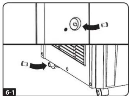
6-3 PekHM ocuHnna
PnNcNoB3OaHmYcTpoCtBaBpeXmmeOcyuEHHBaBbTeBepxHIO CnBHyIO np6knyamocTOAeHIO TBODHyIO NmHIO K CICTEME BHEuHero DpeHaKa. PnN 30mNHJrCNBHAR pNO6a DOJnxHOCabTaBCa H CBOeM MceTe.3To nO3BOJNT ydaIbTbN 3BO3dyxaMaKcIMaJIbHO BO3MOXHoe KOINueCTBO BNar.
Pumuehue. B cnyae 3acopehue dpehakno cuscmeb Ko hdeham kaknlaeaemc 8 heboIbuoi BhympenHeu EMKmo. Ecnu depehakna cuscema He ybdem npoucietao da Momeha zanonhenue BhympenHeu emkocmo, no npou3oed amomamueckoe omknloueny cympoiuemba.
BHMaHne! Npeb noKIOUeHnEM YcTPOECTBA K CNEUaIpaOBaHOJ DpeHAXHOJ CNTeMe EOR cJeYET BkIOuHTb N OTOeHNHTb OT CETN 3JEKTPoNTaHnA. YcTPOCTBO, BKIOUeHHeB Cetb, npEcTbaRt NOTeHuaJIbHyO NOACHOtB NOPaKeHn 3JEKTPnuCekm TOKOM
Ipumeyaue. Ecnu cunema behmua, ycaHOBnHna 8 bawem 3daHuu, 3anpozpaMMUPoBaHa ha chUkeHe 4fekmuBHOcmu oxlaXedHua B HooHoe epMa u bixOohb deH, fyHKUOHpyem c nepuOoUeCKUMU omKIOUeHUMU UU UMeem oepauHUYIO XoJOnDPOUsOBDumEnbHcMb, mo bI MoXeme OKa3amCpe nepe HeobxodumcbPaccmOpneH aupAHMO, npdcmaNIOuux coou anbmeHAMuy WAMHOUCMBO. dHoe u3dene npeHa3hauho dnusocnbogua haoceae BCNOZAMeBHOZO OXaXdoJeO Ycmpoucmeu He MOxem KomneHCupoBam cyuccebeHBe KonebaHure Memnpambyu UIN bJAAhncMoBo BO BCm 3duHau.
Pa60Ta npn Hn3Knx TemnepaTypax
yctpoctbo SRCOOL12K npedctabnertcoBbIcOKOpON3BOIDNTeHbIK KOHNIOHOep, cnoCobHb BdAbaTb Ha BbXoe Bo3dy, oxNaeHHbdo OeyHb HN3kXu Tmepatyp. Pnp NcPON3BOAHAUYCTPOUCTBA SRCOOL12K b NOMEueHHx C yke OxNAeHHBM 03Dxyom (mEoim Temepatpy He Bblwe 20^) KOMNAHTEMIg Lite peKomeHdyet nCpON3BOAHTbToNko peKIM Ocyehnna (Dehumidify Mode). 3to No3BONIT YcTPOJCTBy npoDOAnr bpOdoNaTbpoccc BCNOMOrateBHorO OXIAKDEHnna, h36eran ppr tOM pO6bem C o6NdeEHHEm Ecapntle, BB3bBaEMbx HN3KO Temepatpy B NOMEueHH.
3Kcnpnyataua
BnmaHne!peepaHaonmKcnnyataun daHHoro yctpoicBa npoun3BeNTe ero yctahOBky cornaCHO kka3aHnM, npnbedeHHbIM bpa3dene "YcTaHOBA". PttaHne
BkIIOaJIte N BbIKIOaJIte YcTPOINCTBO IyTEM HkaTnK HONKN "POWER".
Bo n36exaHne Bo3MOKbIX neperpy30K ueenB MOMENT yNcKa yCTpoiCTBO IMeET TpExMNHyTHyIO 3aepkky BKNUHeHn KOMPipeccopa.
Bo3MOxHOCTb abTOMaTHueCKORIO NOBTOPHORO Nycka
PnBocCTaHOBHeHNI NITAHN NOcNE ppeKaeHnIOaun 3NeKTPoHeprnn npOxCODT ABOTMaTHueCKE BKNIOUeHne I BO3OBHOBHeHne pa60tbyCtPOICTBa. Pn TOM yCTPOIcTB O ByET nCNOBb3OBaTb Te Je HAcTPOKn, KOTOpBe I cNOb3OBaUNCb IM HEnOCPeIcTBHeHNo nepeD ppeKaeHm eoau 3NeKTPoHeprnn. IpumeeHae. B Cnyae KpamKobpeMeHHOzo ppeKaeHn oNau 3NeKmpo3Hep2u, nepe 8O3OBHOBHeHem HopMaJbHou pa60mby Ucmpoucmbo Bydem B meHu eM pxM uHy mOblko bpaamb bEmmuJnop. 3ma 3aepkka daem 8O3MOxHoCm6b c6poca daenHua 6 Kompeccope c ueBIO bc6ceueHn npabUbHBO zo fynkuOuHpuOBAHua ycmpoucmba npu nepexode 8 peKUM oxJaXedHeur.
Pekm oxlaeHn
HaxaTHe KhoIKN "FUNCTION" o6eIeHuBaET UKJIuYeCKeO I3MeHeHne MeJx ypeKImaMn OXlaJaDeHn IocUeHn. Pp pa6ote yctpoIcTB a PekIme OXnaJdeHn rOpNT CBeToNDHbI INHdkatop COOLING".
IyctahOBKn Tpe6yemOM TemnepaTpybl B pexime oxlanxdeHn noJb3yTecb KOnkamn TEM+ nTEMP-.UcTaHOBHeHNO 3naeHne TemnPaTpyb OTO6paKaTcN Ha unPpOBom mHnIKaTope. HenocpeDCTBeHNoOce yCTaOBKn XeJaEMOe 3NaeHne NOITBepKJaTeC NtNKpaTHbIM MIRaHMe, nocse zero Ha INdHaKaTope OTO6paKaTcN TekuJee 3NaeHne KOMHaTHoM TemnPaTpybl.
Lcknueckoe nepekniuehme MeJy BbICOKo, cpeHne Hn3KoC kOpocTmBbAeHnBEHTNlAToPA np03BODNTcHnKaTHeM KHNKn "FAN SPEED". Bb6paHHa CkOPOCTb BpauHn BEHTNlAToPA noTBePkaTeCn BkUHcHEm COOTBcTByUeIero CBtOIOHOHO INDInKATOP. PnpYCTAHOBKe ckopctn B pexmm AUTO yCTpoINCTBO Bb6paETCKOPTb BpauHn BEHTNlAToPA ABOMAtueckn CXoJa 3Haehnno 3aAdHNo HnKfTuEeCKoN TEMepaTybl OkpyKaUHero BOzDyua. Nte TmEPaTpAp OKpyKaUHero BOzDyxa HaxOINCTn Hnke 3aAdHORo 3HAeHny, To BEHTNlAToB 6yETBpaatcbA, a CBeTOIOHbH nIHDAKATop COOLING" 6yET MIRaTb, YkA3bBaRa Ha To, YTO KomnPecCOP OTKIOuH. Pnp Bo3O6HOBLeHnpeKIMa OxJaXeHn CBeTOnIOHDn IHdNKaTOp COOLING" HenpepbIBHO ropnt.
POWER
FUNCTION
。
COOLING
TEMP+

TEMP-

O AUTO
Pekim ocyuhenia
HaxaTne KhoNk "FUNCTION" o6ecneuBaet uKlnueckoe n3MeHeHne MeJy pexMamOxnaKeHn I OcyeHH.
Pn npexpoeB pexm ocyeHna 3aropaetc CBeToOnHOh b HndkaTOp DEHUMIDIFY. B pexnme ocyeHneBHTNATOP BPAaETC nOCToHHoN CKopocTbO, a peryIATopoB tEmpepAtyHe DeTByIO. Ira obceueHnOOnMaHb noBoTaB B pexnme ocyeHna 3akpoTe OKHa N Dbepn, BbHbTe BepXHIO CNBHyIO np6kny N npoeBHe OTOBDHyIO mHIO K cStcMe BHeHsHero dpehaxa.
FUNCTION
0
DEHUMIDIFY
Tainep
KhONKa "TIMER" no3BOnJaT 3aDaBaTb BpEm aBTOMaTnueCKoRb BKJIOUeHn HIN OTKnIOUeHn yCTpoNCTBa.
Taimep BkIouenHn (Ppumeyue. Jn npuBedeHn 8 deucmbue fynKuUo "TaIeM 8kIouenHn" ycmpoucmbo doknho 6bmt bkvKnOyeno. Ipeed mem, KAK npubecmu 8deucmbue fynKuUo TaIeM ekluueHn, y6dumecb 8 npabunbnoy cymaHOBKe pekuma,ypoBn meMpnpampyu u ckopocmu epaueHn behmulnapo.) 3aynctme TaIeM HaxaTne KONKn "TIMER". UcTaHOBte Bpema 3aepKnn BkIoueHn yCPOINCTBa (B vacax) cnomouko KONOK TEMP+ n TEMP-. Ha unfpobom INndkaTope OTO6pa3ntcY cTaHOBHeHoe KOInueCTBO cacOB. UcTaHOBka daHHoro 3aueHn 6ydet noTBPexJaHa erO PAnTKpaTHbIM MIRAHmE Ha 3kpaHe, noCne rO OH BO3BpaNTcB Pekim OTo6paKeHn TEkuJeem TEMpePaTypbl.
Taimep otKIOUHn (Ppumueaue. Iy npueeohn 6 decmbue yfHKuuu "Taumep omKIOUeHn" ycmpoocmbo doJnoHc bIbMb kKnOHeo.) 3anyctne taMep haxatme KNOKN "TIMER". YCTaHOBNTe Bpem 3aepkXn OTKIOUHn yCTpoiCTBa (B lacax) C nOmoBko KNOpOK TEMP+ n TEM-. Ha cNPOBOm HINDATope OTObpa3ntcY cTAHOBNEHHO KONueCTBO vacOB. YCTAHOBKa daHHoro 3NaueHn 6ydet noDTBePexJeHaero pTNIkPaTHbIM MraHMe HA ekpahe, NocLe YeO OH BO3BpaTITcB Pekim OTObpaKeHn TEkyeI tempepatypbl.
TIMER
TEMP-
Pexm6ecwymHoi pa6oTbi
B yctpoiCTBe npdycMTpeh peKm6 bcWmHnpoAbaOtby, perynnpuyoOnn oxnaJqEnHe n C nOmoIbTo Ta mepaMnKpOroPecocca B cTaeN 6oeceNeHn 0oee TnxO paObTy bYctpoiCTBa B Tex cnyaAs KOrda ypoebH bWma ABnETCR kpnTuHbIM noka3aTeMe.
Дя npиьденя дан Horo pexmma B deiCtBne haxmite Khonky “QUIET”.пр nтOM 3aropaetc CBetodnDhbl nHdkatop Quiet. YctahOBITE xenaembl ypoBEB tEmpeaTybl, a 3aTeM yctahOBITE taMEp npdoJIKnteHbOHTN klnka 6ecWmHno pa60bl yctpoCTBa. Ha npotJxehnn daHNoro uKlnka naMTb mKnporpoceccopa KoppeKTpye 3aHdHoe 3aHueHene TempeaTybl Ha 0,5°C kaJdble 30 MNHT do MoMeHa troXnEHHa xenaemol TempeaTybl. Pocle doCTHXeHHa TOnI Te mpeaTybl yctpoCTBO NOdePekHBaeT ee Ha npotJxehnn YCTAHOBIneHHorO nepNoDA BpemeHN.
QUIET
0
QUIET
TIMER
TEMP-
BbIaBHeHn yCtpaHHe HcnpaBHOtei
O3NaKOBtEc C npBBeHbIM HnHex Bo3MOXbIM BapHaTAM peHEnr Ip6nem. B cnUyae coxpaHEnra BO3NkWeepo6nembl nocetnte ctpaHcy www.triplite.com/support dnn noJyueHn TExHueckon noDepKKn.
Visit www.triplite.com/warranty today to register the warranty for your new Tripp Lite product. You'll be automatically entered into a drawing for a chance to win a FREE Tripp Lite product!

- Portable Air Conditioning Unit
- Introduction
- Recommended Applications:
- Important Safety Instructions
- SAVE THESE INSTRUCTIONS
- Warnings
- Features
- Front View
- Control Panel
- Installation
- Accessory Parts List:
- Unit Placement
- Warning: Do not use an extension cord to connect the unit to an AC outlet. Use only the power cord that came with the unit.
- Cooling Duct Connection (Optional)
- Installation (continued)
- Exhaust Duct Connection
- Drop Ceiling Exhaust Connection
- Window Exhaust Connection
- Drainage Plug Insertion
- Cooling Mode with Re-Evaporation
- Cooling Mode without Re-Evaporation
- 6-3 Dehumidify Mode
- Warning: Before connecting the unit to a dedicated drainage system, turn it off and unplug it. There is a risk of electric shock while the unit is plugged in.
- Low Temperature Operation
- Operation
- Power
- Automatic Restart Feature
- Cool Mode
- Dehumidify Mode
- Timer
- Quiet Control Mode
- Changing Degree Units
- Operation (continued)
- Alarm
- Maintenance
- Cleaning the Air Filters
- Cleaning the Cabinet
- Troubleshooting
- Troubleshooting (continued)
- Additional Display Error Codes
- Storage and Service
- Storage
- Service
- Warranty and Warranty Registration
- Warranty
- 1-YEAR LIMITED WARRANTY
- WARRANTY REGISTRATION
- Regulatory Compliance Identification Numbers
- Introduccion
- Alarma
- Installation (suite)
- PykoBoDCTBO NOIb3OBaTeJa
- Ipehenochoi 6lOK KOHdNcNoHnpOBaHnA
- BVeDHeHne
- Baxhblye yka3aHnno ToxHnke 6e30nacHOCTn
- COXPAHNTE HACTOJIUE YKA3AHNA
- PpeynpekdeHna
- Bo3MOXHOCTN (cBOIcTBA)
- BnCnepeN
- Panaelb ynpablenna
- YctaHOBKa
- IpepeHb KOMnKeKTyIoUxh:
- Pa3MeueHne yctpOcnCTBa
- BHMnHHe Hcnonb3yUte shyp-ydnnHntenb nIpaNIOKnIOUeHHy UcpoTcbA KpOaTeKecTe npemehHoro Toka. Mcnonb3yUte ToIbKO uHyp NITAHn, NoCTABnEMyB KOMnNEKe CycTOPcTBOM.
- NpOcOeHHeHne Bo3dyXoBOda oxlaJckEnn (onCNoHaJIbHo)
- YctaHOBKa (npoJOnxHeHne)
- NpOcOeUNHeHne BbITXKHO BO3dYxOBOda
- YctaHOBKa (npoDOnxHeHne)
- IpoBOJka BbITaXHOrO Bo3dyXoBOJa Chepe 1oDBeCHOI NOToJOK
- BbITaKkaYepe3 OKHO
- yctahOBka (npoDonxhen)
- PexnM OxnaKeHnC nOBToPbHM nCapaepHnEM
- 6-2 Pekim oxlaeHn 63 nobTopHO ncapenHn
- 6-3 PekHM ocuHnna
- Pa60Ta npn Hn3Knx TemnepaTypax
- 3Kcnpnyataua
- BnmaHne!peepaHaonmKcnnyataun daHHoro yctpoicBa npoun3BeNTe ero yctahOBky cornaCHO kka3aHnM, npnbedeHHbIM bpa3dene "YcTaHOBA". PttaHne
- Bo3MOxHOCTb abTOMaTHueCKORIO NOBTOPHORO Nycka
- Pekm oxlaeHn
- Pekim ocyuhenia
- Tainep
- Pexm6ecwymHoi pa6oTbi
- BbIaBHeHn yCtpaHHe HcnpaBHOtei
Brand : Tripp Lite
Model : SMARTRACK
Category : Air Conditioning