VDPL1003CW - Effect machine HQ Power - Free user manual and instructions
Find the device manual for free VDPL1003CW HQ Power in PDF.

User questions about VDPL1003CW HQ Power
0 question about this device. Answer the ones you know or ask your own.
Ask a new question about this device
Download the instructions for your Effect machine in PDF format for free! Find your manual VDPL1003CW - HQ Power and take your electronic device back in hand. On this page are published all the documents necessary for the use of your device. VDPL1003CW by HQ Power.
USER MANUAL VDPL1003CW HQ Power
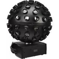
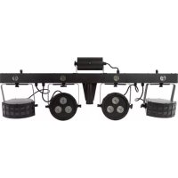
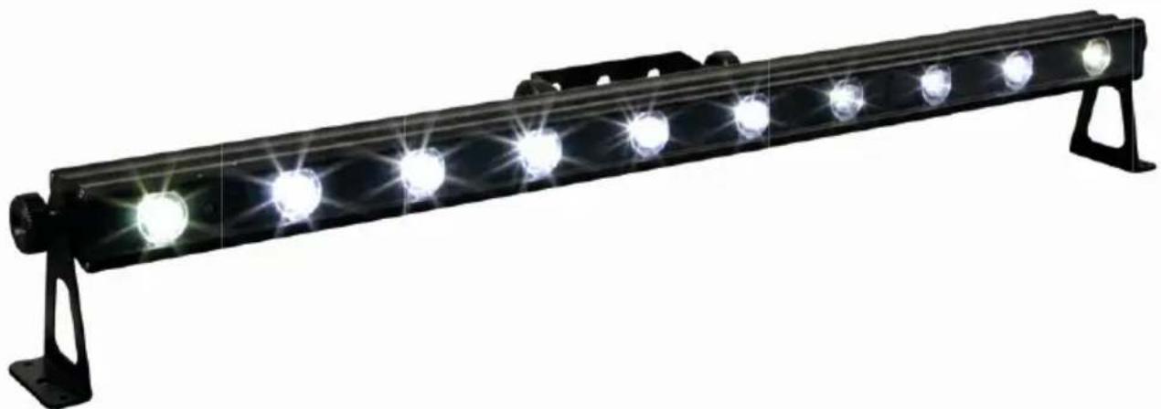
SMART LED BEAM - 10 x 3W WHITE LEDs
SMART LED PROJECTOR - 10 x 3W WITTE LEDS
PROJECTEUR SMART LED - 10 LED DE 3W
FOCO SMART LED - 10 LEDs DE 3W
SMART LED-SCHEINWERFER - 10 x 3W LEDs
natural_image
Black rectangular LED array with multiple illuminated circular lights, mounted on a metal frame (no text or symbols visible)| VDPL1003CW | cold whitekoud witblanc froidblanco fríokaltweiß |
| VDPL1003WW | warm whitewarm witblanc chaudblanco cálidowarmweiß |
USER MANUAL 3
GEBRUIKERSHANDLEIDING 9
NOTICE D'EMPLOI 15
MANUAL DEL USUARIO 21
To all residents of the European Union
Important environmental information about this product
This symbol on the device or the package indicates that disposal of the device after its lifecycle could harm the environment. Do not dispose of the unit (or batteries) as unsorted municipal waste; it should be taken to a specialized company for recycling. This device should be returned to your distributor or to a local recycling service. Respect the local environmental rules.
If in doubt, contact your local waste disposal authorities.
Thank you for choosing HQ-power! Please read the manual thoroughly before bringing this device into service. If the device was damaged in transit, do not install or use it and contact your dealer.
For more info concerning this product and the latest version of this user manual, please visit our website www.hqpower.eu.
2. Safety Instructions
 | Be very careful during the installation: touching live wires can cause lfe-threatening electroshocks. | |
 | Always disconnect mains power when device not in use or when servicing or maintenance activities are performed. Handle the power cord by the plug only. | |
 | Indoor use only. Keep this device away form rain, moisture, splashing and dripping liquids. | |
 | Keep this device away from children and unauthorized users. | |
 | Caution: device heats up during use. | |
 | Do not stare directly at the light source, as this may cause-epileptic seizure in sensitive people-temporarily loss of sight (flash blindness)-permanent (irreversible) eye damage | |
 | There are no use r-serviceable parts inside the device. Refer to an authorized dealer for service and/or spare parts. |
- This device falls under protection class I. It is therefore essential that the device be earthed. Have a qualified person carry out the electric connection.
- Make sure that the available voltage does not exceed the voltage stated in the specifications of this manual.
- Do not crimp the power cord and protect it against damage. Have an authorised dealer replace it if necessary.
- Respect a minimum distance of 0.5m between the device's light output and any illuminated surface.
- Use an appropriate safety cable to fix the device (e.g. VDLSC7 or VDLSC8).
- Inst all the VDPL10()3xW at a minimal distance of 0.5 m from flammable and explosive objects or substances.-Keep the VDPL1003xW at a minimal distance of 1 m from the lighted surface.
- Keep the air vents free at all times. Never cover the device, nor partially, nor completely.
3. General Guidelines
Refer to the Velleman® Service and Quality Warranty on the last pages of this manual.
 | Keep this device away from dust and extreme heat. Make sure the ventilation openings are clear at all times. For sufficient air circulation, leave at least 1" (±2.5 cm) in front of the openings. | |
 | Protect this device from shocks and abuse. Avoid brute force when operating the device. | |
- Familiarise yourself with the functions of the device before actually using it. Do not allow operation by unqualified people. Any damage that may occur will most probably be due to unprofessional use of the device.
- All modifications of the device are forbidden for safety reasons. Damage caused by user modifications to the device is not covered by the warranty.
VDPL1003xW
- Mechanical wear is not covered by warranty.
- Only use the device for its intended purpose. All other uses may lead to short circuits, burns, electroshocks, lamp explosion, crash, etc. Using the device in an unauthorised way will void the warranty.
- Damage caused by disregard of certain guidelines in this manual is not covered by the warranty and the dealer will not accept responsibility for any ensuing defects or problems.
• A qualified technician should install and service this device. - Do not switch the device on immediately after it has been exposed to changes in temperature. Protect the device against damage by leaving it switched off until it has reached room temperature.
- This device is designed for professional use on stage, in discos, theatres, etc. The VDPL1003xW can be used indoor (<35°C, <75%RH) with an alternating current of max. 240V AC/50Hz.
- Lighting effects are not designed for permanent operation: regular operation breaks will prolong their lives.
• Use the original packaging if the device is to be transported. - Keep this manual for future reference.
4. Features
• 12 channel in DMX mode for separate control of each LED
- master dimmer and shutter via DMX mode
• built-in programs for stand-alone and sound activated modes
- pulse effect with adjustable speed
• additional power output up to 10pcs at 230VAC
- truss or floor mounting
5. Overview
Refer to the illustrations on page 2 of this manual.
| 1 display with control buttons 4 DMX output | ||||
| A | MODE button | 5 | sound sensitivity adjustment knob | |
| B | UP button | 6 | power input/fuse holder | |
| C | DOWN button 7 GND | |||
| 2 microphone 8 power output | ||||
| 3 DMX input | ||||
6. Installation
Refer to the illustrations on page 2 of this manual.
a) Overhead mounting
- Have the device installed by a qualified person, respecting EN 60598-2-17 and all other applicable norms.
- The construction to which the device is attached should be able to support 10 times the weight of the device for one hour without deformation.
- The installation must always be secured with a secondary attachment e.g. a safety cable.
- Never stand directly below the device when it is being mounted, removed or serviced. Have a qualified technician check the device once a year and once before you bring it into service.
• Install the device in a location with few passers-by and inaccessible to unauthorised persons. - Overhead mounting requires extensive experience: calculating workload limits, determining the installation material to be used... Have the material and the device itself checked regularly. Do not attempt to install the device yourself if you lack these qualifications as improper installation may result in serious injuries.
- For truss-mounting, use an appropriate clamp (not incl.) and fit an M10 bolt through the centre of the (folded) bracket.
- Adjust the desired inclination angle via the mounting bracket and tighten the bracket screws.
b) DMX-512 connection
- When applicable, connect an XLR cable to the female 3-pin XLR output of a controller (not incl.) and the other side to the male 3-pin XLR input of the VDPL1003xW. Multiple VDPL1003xW's can be linked through serial linking. The linking cable should be a dual core, screened cable with XLR input and output connectors.
- Maximum recommended serial data link distance is 500 meters (1640 ft). Maximum recommended number of fixtures on a serial data link is 32 fixtures.
- A DMX terminator is recommended for installations where the DMX cable has to run a long distance or is in an electrically noisy environment (e.g. discos). The terminator prevents corruption of the
VDPL1003xW
digital control signal by electrical noise. The DMX terminator is simply an XLR plug with a 120Ω resistor between pins 2 and 3, which is then plugged into the XLR output socket of the last device in the chain.
c) general
- Make sure there is no flammable material within a 50cm radius of the device and there is sufficient cooling.
- Have a qualified electrician carry out the electrical connection.
- All fixtures must be powered directly off a grounded switched circuit and cannot be run off a rheostat or dimmer circuit, even if the rheostat or dimmer channel is used solely for 0% to 100% switch.
- The installation has to be approved by an expert before the device is taken into service.
7. Operation
Refer to the illustrations on page 2 of this manual.
Menu Functions
| menu | function | description | |
| stand-alone | p- | built-in programsP- 1 ~ P- 10 | select between switching and fading built-in programs(P- 10 = loop of P- 1 ~ P- 9) |
| speed5000 ~ 5 100 | select running speed of the internal program5000 = slow, 5 100 = fast | ||
| SoUd | sound mode | set he LED bar into sound activated mode | |
| Slave DMX | SLAU | slave mode | set he LED bar into slave mode |
| d--- | address | set DMX address (d001 ~ d5 12) | |
| SCH | channel mode | selección modo DMX 5 canales (+dirección) | |
| I2CH | selección modo DMX 12 canales (+dirección) |
Stand-Alone Mode
Auto Mode
- Press
until P- isplayed - Use
or to select the desired program P - 1 P - 10 ( P - 10 = loop of P - 1 P - 9 ). - Press
until 5 - isplayed - Use
or to select the desired running speed 5000 \~ 5100 (5000 = ow, s 5100 = fast).
Sound-Active Mode
This mode allows a single unit to run to the beat of the music.
- Press
until SoUD displayed. - Use the audio sensitivity knob on the back of the fixture [5] to make the fixture more or less sensitive.
Slave Mode
This mode allows a unit to follow the output of a master unit which has been set to Auto or Sound-Active mode.
- Set the master unit to auto or sound-activated mode.
- On each slave unit, press
until SLAU is displayed.
DMX Mode
This mode allows you to control the fixture by any universal DMX controller.
- All DMX-controlled devices need a digital start address so that the correct device responds to the signals. This digital start address is the channel number from which the device starts to "listen" to the DMX controller. The same starting address can be used for a whole group of devices or an individual address can be set for every device.
- When all devices have the same address, all the units will "listen" to the control signal on one
VDPL1003xW
particular channel. In other words: changing the settings of one channel will affect all devices simultaneously. If you set individual addresses, each device will "listen" to a separate channel number. Changing the settings of one channel will only affect the device in question.
Example:
- I n case of the 5-channel VDPL1003xW, you will have to set the start address of the first unit to 1 (CH1\~5), the second unit to 6 (1 + 5) (CH6\~10), the third to 11 (6 + 5) (CH11\~15), and so on.
- In case of the 12-channel VDPL 1003xW, you will have to set the start address of the first unit to 1 (CH1\~12), the second unit to 13 (1 + 12) (CH13\~24), the third to 25 (13 + 12) (CH25\~36), and so on.
- Press
until the DMX channel mode ( SCH or 12CH) is displayed.
• Useor to select the desired DMX mode ( SCH or 12CH mode) - Press
until the DMX address (d---) is shown. - Use
or to set the desired starting address (d001 \~ d512).
DMX Channel Values
5-Channel Mode
| channel | from | to | description | |||||||||
| 1 | 000 | 255 | dimer 0 ~ 100% | |||||||||
| 2 | 000 | 009 | nfunction | |||||||||
| 010 | 255 | Sobe: slow ~ fast (max. 20Hz) | ||||||||||
| 3 | 000 | 010 | nfunction | |||||||||
| 011 | 047 | Ao 1 | ||||||||||
| 048 | 071 | Ao 2 | ||||||||||
| 072 | 095 | Ao 3 | ||||||||||
| 096 | 119 | Ao 4 | ||||||||||
| 120 | 143 | Ao 5 | ||||||||||
| 144 | 167 | Ao 6 | ||||||||||
| 168 | 191 | Ao 7 | ||||||||||
| 192 | 215 | Ao 8 | ||||||||||
| 216 | 239 | Ao 9 | ||||||||||
| 240 | 249 | Ao 10 (=loop of Auto 1 ~ Auto 9) | ||||||||||
| 250 | 255 | sond controlled | ||||||||||
| 4 | 000 | 255 | Ao-speed: slow ~ fast (when channel 3 = 011~249) | |||||||||
| fr | cm | to | L1 | L2 | L3 | L4 | L5 | L6 | L7 | L8 | L9 | L10 |
| 010 | 002 | √ √ √ | √ √ | √ √ √ | √ √ | |||||||
| 013 | 005 | √ | - | - | - | - | - | - | - | - | - | |
| 016 | 008 | - | √ | - | - | - | - | - | - | - | - | |
| 019 | 011 | - | - | √ | - | - | - | - | - | - | - | |
| 022 | 014 | - | - | - | √ | - | - | - | - | - | - | |
| 025 | 017 | - | - | - | - | √ | - | - | - | - | - | |
| 028 | 020 | - | - | - | - | - | √ | - | - | - | - | |
| 021 | 023 | - | - | - | - | - | - | √ | - | - | - | |
| 024 | 026 | - | - | - | - | - | - | - | √ | - | - | |
| 027 | 029 | - | - | - | - | - | - | - | - | √ | - | |
| 030 | 032 | - | - | - | - | - | - | - | - | - | √ | |
| 033 | 035 | √ √ | - | - | - | - | - | - | - | - | ||
| 036 | 038 | √ | - | √ | - | - | - | - | - | - | - | |
| 039 | 041 | √ | - | - | √ | - | - | - | - | - | - | |
| 042 | 044 | √ | - | - | - | √ | - | - | - | - | - | |
| 045 | 047 | √ | - | - | - | - | √ | - | - | - | - | |
| 048 | 050 | √ | - | - | - | - | - | √ | - | - | - | |
| 051 | 053 | √ | - | - | - | - | - | - | √ | - | - | |
| 054 | 056 | √ | - | - | - | - | - | - | - | √ | - | |
| 057 | 059 | √ | - | - | - | - | - | - | - | - | √ | |
| 060 | 062 | - | √ √ | - | - | - | - | - | - | - | ||
| 063 | 065 | - | √ | - | √ | - | - | - | - | - | - | |
| 066 | 068 | - | √ | - | - | √ | - | - | - | - | - | |
| 069 | 071 | - | √ | - | - | - | √ | - | - | - | - | |
| 072 | 074 | - | √ | - | - | - | - | √ | - | - | - | |
VDPL1003xW
| from | to | L1 | L2 | L3 | L4 | L5 | L6 | L7 | L8 | L9 | L10 | |
| 075 | 077 | -✓ | - | - | - | - | - | ✓ | - | - | ||
| 078 | 080 | -✓ | - | - | - | - | - | - | ✓ | - | ||
| 081 | 083 | -✓ | - | - | - | - | - | - | - | ✓ | ||
| 084 | 086 | - | ✓ -✓ | - | - | - | - | - | - | |||
| 087 | 089 | - | ✓ - | - | ✓ | - | - | - | - | - | ||
| 090 | 092 | - | ✓ - | - | - | ✓ | - | - | - | - | ||
| 093 | 095 | - | ✓ - | - | - | - | ✓ | - | - | - | ||
| 096 | 098 | - | ✓ - | - | - | - | - | ✓ | - | - | ||
| 099 | 101 | - | ✓ - | - | - | - | - | - | ✓ | - | ||
| 102 | 104 | - | ✓ - | - | - | - | - | - | - | ✓ | ||
| 105 | 107 | - | - | - | ✓ ✓ | - | - | - | - | - | ||
| 108 | 110 | - | - | - | ✓ | - | ✓ | - | - | - | - | |
| 111 | 113 | - | - | - | ✓ | - | - | ✓ | - | - | - | |
| 114 | 116 | - | - | - | ✓ | - | - | - | ✓ | - | - | |
| 117 | 119 | - | - | - | ✓ | - | - | - | - | ✓ | - | |
| 120 | 122 | - | - | - | ✓ | - | - | - | - | - | ✓ | |
| 123 | 125 | - | - | - | - | ✓ ✓ | - | - | - | - | ||
| 126 | 128 | - | - | - | - | ✓ | - | ✓ | - | - | - | |
| 129 | 131 | - | - | - | - | ✓ | - | - | ✓ | - | - | |
| 132 | 134 | - | - | - | - | ✓ | - | - | - | ✓ | - | |
| 135 | 137 | - | - | - | - | ✓ | - | - | - | - | ✓ | |
| 138 | 140 | - | - | - | - | - | ✓ ✓ | - | - | - | ||
| 141 | 143 | - | - | - | - | - | ✓ | - | ✓ | - | - | |
| 144 | 146 | - | - | - | - | - | ✓ | - | - | ✓ | - | |
| 147 | 149 | - | - | - | - | - | ✓ | - | - | - | ✓ | |
| 150 | 152 | - | - | - | - | - | - | ✓ ✓ | - | - | ||
| 153 | 155 | - | - | - | - | - | - | ✓ | - | ✓ | - | |
| 156 | 158 | - | - | - | - | - | - | ✓ | - | - | ✓ | |
| 159 | 161 | - | - | - | - | - | - | - | ✓ ✓ | - | ||
| 162 | 164 | - | - | - | - | - | - | - | ✓ | - | ✓ | |
| 165 | 167 | - | - | - | - | - | - | - | - | ✓ ✓ | ||
| 168 | 170 | ✓ ✓ ✓ ✓ | - | - | - | - | - | - | ||||
| 171 | 173 | ✓ ✓ | - | - | ✓ ✓ | - | - | - | - | |||
| 174 | 176 | ✓ ✓ | - | - | - | - | ✓ ✓ | - | - | |||
| 177 | 179 | ✓ ✓ | - | - | - | - | - | - | ✓ ✓ | |||
| 180 | 182 | - | ✓ -✓ ✓ ✓ | - | - | - | - | |||||
| 183 | 185 | - | ✓ -✓ | - | - | ✓ ✓ | - | - | ||||
| 186 | 188 | - | ✓ -✓ | - | - | - | - | ✓ ✓ | ||||
| 189 | 191 | - | - | - | - | ✓ ✓ ✓ ✓ | - | - | ||||
| 192 | 194 | - | - | - | - | ✓ ✓ | - | - | ✓ ✓ | |||
| 195 | 197 | ✓ ✓ ✓ | - | - | - | - | - | - | - | |||
| 198 | 200 | -✓ ✓ ✓ | - | - | - | - | - | - | ||||
| 201 | 203 | - | ✓ -✓ ✓ | - | - | - | - | - | ||||
| 204 | 206 | - | - | - | ✓ ✓ ✓ | - | - | - | - | |||
| 207 | 209 | - | - | - | - | ✓ ✓ ✓ | - | - | - | |||
| 210 | 212 | - | - | - | - | - | ✓ ✓ ✓ | - | - | |||
| 213 | 215 | - | - | - | - | - | - | ✓ ✓ ✓ | - | |||
| 216 | 218 | - | - | - | - | - | - | - | ✓ ✓ ✓ | |||
| 219 | 221 | ✓ ✓ ✓ | - | - | - | - | ✓ ✓ ✓ | |||||
| 222 | 224 | - | ✓ -✓ | - | - | ✓ ✓ | - | - | ||||
| 225 | 227 | ✓ ✓ ✓ ✓ | ||||||||||
| 228 | 230 | ✓ ✓ | - | - | ✓ ✓ | - | - | ✓ ✓ | ||||
| 231 | 233 | ✓ | ✓ | ✓ | ✓ | ✓ | - | - | - | - | - | |
| 234 | 236 | - | - | - | - | - | ✓ | ✓ | ✓ | ✓ | ✓ | |
| 237 | 255 | ✓ | ✓ | ✓ | ✓ | ✓ | ✓ | ✓ | ✓ | ✓ | ✓ | |
VDPL1003xW
12-Channel Mode
| channel | LED | from | to | description |
| 1 all | 000 255 | dimmer 0 ~ | 100% | |
| 2 | all | 000 | 009 | no function |
| 010 255 strobe slow ~fast (max. 20Hz) | ||||
| 3 1 | 000 255 | dimmer 0 ~ | 100% | |
| 4 2 | 000 255 | dimmer 0 ~ | 100% | |
| 5 3 | 000 255 | dimmer 0 ~ | 100% | |
| 6 4 | 000 255 | dimmer 0 ~ | 100% | |
| 7 5 | 000 255 | dimmer 0 ~ | 100% | |
| 8 6 | 000 255 | dimmer 0 ~ | 100% | |
| 9 7 | 000 255 | dimmer 0 ~ | 100% | |
| 10 8 | 000 255 | dimmer 0 ~ | 100% | |
| 11 9 | 000 255 | dimmer 0 ~ | 100% | |
| 12 | 10 | 000 | 255 | dimmer 0 ~ 100% |
8. Cleaning and maintenance
- All screws should be tight and free of corrosion.
- The housing, the lenses, the mounting supports and the installation location (e.g. ceiling, suspension, trussing) should not be deformed, modified or tampered with e.g. do not drill extra holes in mounting supports, do not change the location of the connections ...
- The electric power supply cables must not show any damage. Have a qualified technician maintain the device.
• Regularly remove dust from the housing and the air vents using a slightly damp cloth. - There are no user-serviceable parts inside. Refer to an authorized dealer for service and/or spare parts.
Fuse Replacement
- Wedge the fuse holder out of its housing with a flat-head screwdriver.
- Remove the damaged fuse from its holder and replace with exact same type of fuse.
- Insert the fuse holder back in its place and reconnect power.
9. Technical specifications
| VDPL1003CW | VDPL1003WW | |
| power supply | 230VAC ~ 50Hz | |
| power consumption | 37 W | |
| LEDs | 10 x CREE® 3W cold white | 10 x CREE® 3W warm white |
| beam angle | 140° | |
| luminous flux | 1200 @ 1m | 1050 @ 1m |
| dimensions | 1060 x 58 x 148mm | |
| weight | 3.5 kg | |
Use this device with original accessories only. Velleman nv cannot be held responsible in the event of damage or injury resulted from (incorrect) use of this device. The information in this manual is subject to change without prior notice.
© COPYRIGHT NOTICE
The copyright to this manual is owned by Velleman nv. All worldwide rights reserved.
No part of this manual or may be copied, reproduced, translated or reduced to any electronic medium or otherwise without the prior written consent of the copyright holder.
GEBRUIKERSHANDLEIDING
1. Inleiding
Velleman® Service and Quality Warranty
Velleman® has over 35 years of experience in the electronics world and distributes its products in more than 85 countries.
All our products fulfil strict quality requirements and legal stipulations in the EU. In order to ensure the quality, our products regularly go through an extra quality check, both by an internal quality department and by specialized external organisations. If, all precautionary measures notwithstanding, problems should occur, please make appeal to our warranty (see guarantee conditions).
General Warranty Conditions Concerning Consumer Products (for EU):
- All consumer products are subject to a 24-month warranty on production flaws and defective material as from the original date of purchase.
- Velleman® can decide to replace an article with an equivalent article, or to refund the retail value totally or partially when the complaint is valid and a free repair or replacement of the article is impossible, or if the expenses are out of proportion.
You will be delivered a replacing article or a refund at the value of 100% of the purchase price in case of a flaw occurred in the first year after the date of purchase and delivery, or a replacing article at 50% of the purchase price or a refund at the value of 50% of the retail value in case of a flaw occurred in the second year after the date of purchase and delivery.
• Not covered by warranty:
- all direct or indirect damage caused after delivery to the article (e.g. by oxidation, shocks, falls, dust, dirt, humidity...), and by the article, as well as its contents (e.g. data loss), compensation for loss of profits;
- frequently replaced consumable goods, parts or accessories such as batteries, lamps, rubber parts, drive belts... (unlimited list);
- flaws resulting from fire, water damage, lightning, accident, natural disaster, etc. ...;
- flaws caused deliberately, negligently or resulting from improper handling, negligent maintenance, abusive use or use contrary to the manufacturer's instructions;
- damage caused by a commercial, professional or collective use of the article (the warranty validity will be reduced to six (6) months when the article is used professionally);
- damage resulting from an inappropriate packing and shipping of the article;
- all damage caused by modification, repair or alteration performed by a third party without written permission by Velleman®.
- Articles to be repaired must be delivered to your Velleman® dealer, solidly packed (preferably in the original packaging), and be completed with the original receipt of purchase and a clear flaw description.
- Hint: In order to save on cost and time, please reread the manual and check if the flaw is caused by obvious causes prior to presenting the article for repair. Note that returning a non-defective article can also involve handling costs.
- Repairs occurring after warranty expiration are subject to shipping costs.
- The above conditions are without prejudice to all commercial warranties.