
BX 710 - Drill Güde - Free user manual and instructions
Find the device manual for free BX 710 Güde in PDF.

| Product type | Percussion drill |
| Brand | Güde |
| Model | BX 710 |
| Supply voltage | 230 V ~ 50 Hz |
| Motor power | 810 W |
| No-load speed | 0-290 rpm |
| Impact rate | 0-52,200 bpm |
| Chuck capacity | 2-13 mm |
| Drilling capacity steel | 13 mm |
| Drilling capacity wood | 32 mm |
| Drilling capacity stone | 13 mm |
| Cable length | 3 m |
| Sound pressure level | 92.5 dB(A) |
| Sound power level | 103.5 dB(A) |
| Vibration | 2.5 m/s² |
| Rotation direction | Left / Right |
| Variable speed | Yes (electronic) |
| Drilling / hammer mode | Switchable |
| Auxiliary handle | Included |
| Depth stop | Included |
| Keyless chuck | Yes |
| Double insulation | Yes |
| Maintenance | Clean with a damp cloth, no solvents |
| Repairs | By qualified personnel with original parts |
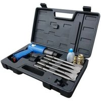
| Package contents | Drill, steel drill bits, wood drill bit, stone drill bit, keyless chuck, auxiliary handle, depth stop |
Frequently Asked Questions - BX 710 Güde
User questions about BX 710 Güde
0 question about this device. Answer the ones you know or ask your own.
Ask a new question about this device
Download the instructions for your Drill in PDF format for free! Find your manual BX 710 - Güde and take your electronic device back in hand. On this page are published all the documents necessary for the use of your device. BX 710 by Güde.
USER MANUAL BX 710 Güde
natural_image
Icon of an open book inside a black circle (no text or symbols)Deutsch D 2
Translation of original operating instructions
IMPACT DRILL
Čeština CZ 12
EC-DECLARATION OF CONFORMITY • PROHLÁŠENÍ O
SHODĚ EU • IZJAVA O SUKLADNOSTI EU • VYHLAŠENIE
O ZHODE EU • DECLARATION CE DE CONFORMITE
natural_image
Exterior view of a modern electric drill putter with black handle and grip (no visible text or symbols)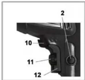
Abb. 1
 _ _ | [54cw] Please read carefully the following Operating Instructions before putting the appliance into operation | ||
| A.V. 2 Any reprints, even partial, are subject to approval. Technical changes reserved. Illustrative pictures! Translation of original operating instructions. | |||
| Any technical questions? Complaint? Do you need spare parts or operation manual? Go to our website www.guede.com and the section Service will help you quickly and without bureaucracy. Please, help us to help you. In order to identify your device in case of complaint, please indicate serial number, order number and year of manufacture. All information is available on the product label. To have all information always at hand, put them down. | |||
| Serial number: Order number: Year of manufacture: | |||
| Phone: +49 (0) 79 04 / 700-360 | Fax: +49 (0) 79 04 / 700-51999 | E-Mail: support@ts.guede.com | |
Every effort is made to improve our products continuously. Therefore, technical data and figures are subject to change
Unit
Scope of Delivery
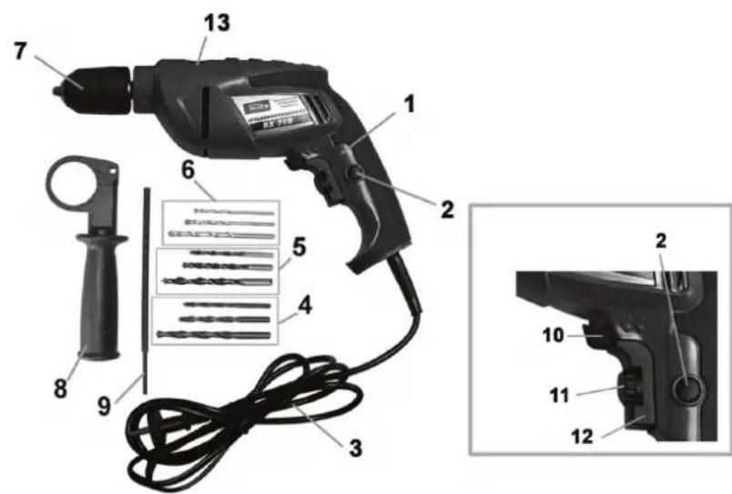
Fig. 1
- Impact drill
- Locking button
- Power cable
- Steel drills
- Wood drills
- Stone drills
- Quick clamping chuck
- Auxiliary handle
- Depth stop
- Rotational direction (right/left) switch
- Speed control
- On/Off switch
- Drilling/Impact switch
Warranty
A warranty period of 12 months applies to commercial use and 24 months apply to private use and commences on the day of purchase of the device.
Warranty applies exclusively to failures due to defective material or workmanship. An original sale slip with indication of date of sale must be presented in case of claiming for the warranty rights.
Warranty does not cover unprofessional use such as device overload, violent use, damage caused by third party or foreign materials, failure to comply with operations and assembly manual, and normal wear and tear.
General Safety Instructions
Prior to the initial use of the unit, the operating instructions should be read completely. If in doubt with regard to connection and operation of the unit, consult the manufacturer (servicing department).
FOLLOW THE INSTRUCTIONS BELOW CAREFULLY IN ORDER TO SECURE A HIGH DEGREE OF SAFETY:
CAUTION!
Use of electrical tools requires observation of the following fundamental safety measures to protect against risk of electrical shock and fire. Read all the instructions before start using the electrical tools. Keep the instructions safe.
Safe Work
- Keep your workplace tidy
Disorder may result in accidents
- Take the ambient effects into account
Never use electric tools in rainy weather. Never use the electric tools in moist and wet surroundings. Provide for good lighting. Do not use the electric tools in the proximity of flammable liquids and gases.
Get protected from electric shock. Avoid any contact of the body with grounded parts, such as pipes,
heating radiators, stoves, and refrigerators.
- Keep away from children. Do not let other persons touch the electric tools or cables. Prevent other people from access to your workbench.
- Store the electric tools at a safe place.
The tools not in use should be stored at a dry, elevated or closed place outside the reach of children.
Do not overload your electric tools. Your job will be done better and safer if within the indicated scope of output.
- Use correct electric tools.
- Do not use low power tools for demanding jobs. Do not use any electric tools for purposes, which they do not match. Use the electric tools only for purposes described in the manual.
- Wear suitable working clothes.
Do not wear lose clothing or jewellery, they could be caught with moving parts. When working outdoors, rubber gloves and antiskid boots are recommended. If your hair is long, hair protective net should be worn.
- Wear protective goggles
Wear a dustproof respirator at works generating dust.
- Do not use the cable for other purposes than it is intended for.
- Never carry the tool by cable. Do not use the cable to pull out the plug from the socket. Protect the cable from excessive temperatures, oil and sharp edges.
- Secure the work piece. Use vice or fixture to clamp the work piece. The job is thus held safer than by hand and in addition, you have got hands free to operate the tool.
- Avoid any abnormal posture. Stand safety and keep balance
Take care of your tools. Keep your tools sharp and clean so that your work is good and safe. Observe the maintenance regulations and instructions for the tool replacement. Check the tool cable regularly and if damaged, have it replaced by an authorised professional. Check extension cables on a regular basis and replace them when damaged. Keep handgrips dry, without any oil and grease
- Pull the plug out of the socket. If the electrical tool is out of use, before maintenance or replacement of accessories – blades, bits etc.
- Do not leave any wrenches in.
- Before turning on, check to see that any wrenches and adjustment tools are removed.
- Prevent unintentional start-up.
Do not carry any electric tools connected to the mains with your finger on the switching push button. Make sure that the switch is off when the tool is being plugged.
Extension cables used outdoors. When working outdoors, use only the cables authorised for the purpose and marked in an appropriate way.
- Be attentive.
- Mind what you are doing. Use common sense while working. Do not use the electric tools unless fully concentrated.
- Check the machine regularly for any signs of damage.
Before using the machine, it is unconditional to check the safety devices. Make sure that all the parts, apparently only slightly damaged, work properly. Check the working condition of all the moving parts. Primarily, pay attention to any damaged and stuck parts. Any parts should be installed correctly and meet all the conditions of perfect functioning. Any damaged protective devices and parts should be repaired or replaced by an authorised professional shop unless otherwise stated in the manual. Have any damaged switches replaced at an authorised servicing centre. Do not use the tools on which switches cannot be put on and off.
CAUTION
- Use only the accessories and attachments shown in the operation manual. Use of other spare parts and accessories may result in a risk of injury.
- This electric tool meets respective safety regulations. Repairs should be done by professional electrician only using original spare parts. Proceeding contrary to this provision, the operator might face a risk of accidents.
Emergency Action
Apply the first aid adequate to the injury and get qualified medical assistance as quickly as possible. Protect the injured person from more accidents and calm him/her down.
For the sake of eventual accident, in accordance with DIN 13164, a workplace has to be fitted with a first-aid kit. It is essential to replace any used material in the first-aid kit immediately after it has been used. If you seek help, state the following pieces of information:
-
Accident site
-
Accident type
-
Number of injured persons
-
Injury type(s)
Signs on Unit
Meaning of Symbols
Symbols shown below are used throughout this manual and/or on the unit:
Product Safety
 |  | ||||
| Product compliance with respective EU standards | Protection | insulation |
Environment Protection:
 |  |  | ||||||
| Wastes to be disposed of in a professional manner not to harm the environment. | Cardboard packaging to be collected for recycling. | Faulty and/or disposed of electrical/electronic appliances to be collected by authorised salvage places. | ||||||
Packaging:
 |  |  | ||||||
| Protect from moisture | Keep Up Fragile | |||||||
Technical data:
 |  | |||||
| Power | connection | Motor | capacity | |||
Product specific:
 |  |  | [3470] | ||
| Speed (rpm) Impacts number Left run/Right run Drilling capacity | |||||
Assigned Use
The manufacture shall not be held liable for any damage should the provision of general regulations and this instruction manual be not observed.
Disposal
Disposal instructions are illustrated in the form of pictograms on the device or packaging. Description of the pictograms is given in "Identification" chapter.
Disposal of transport packaging
Packaging protects the device against damage during transport. Packaging materials are usually selected according to their effect on environment and disposal methods and can therefore be recycled.
Returning of the packaging back to circulation saves resources and costs for packaging disposal.
Parts of the packaging (e.g. foil, styropor) may be dangerous for children. Risk of suffocation!
Keep these parts of the packaging out of reach of children and dispose as soon as possible.
Operator Requirement
The operator is required to read the operating instructions before use.
Qualification
No special qualification is required for use of the unit except for detailed direction by a professional.
Minimum Age
No special limits by age apply to this machine. Use is related to the body height and strength of the user.
Training
Use of the unit requires adequate lesson by a professional or the use of the manual only. Special training is not required.
Technical Data
| BX 710 | |
| Input power: 230 V~50 Hz | |
| Motor output power 810 W | |
| Speed 0-2900 rpm. | |
| Impact rate 0-52200 /min | |
| Quick clamping chuck 2-13 mm | |
| Drilling output steel 13 mm | stone 13 mmwood 32 mm |
| Cable length 3 m | |
| Vibrations a_w 2,5 m/s | ^2 |
| Acoustic pressure level LP_A 92,5 dB(A) | |
| Acoustic power level LW_A 103,5 dB (A) | |
| Ordering number.: 58020 |
Initial Operation Safety Instructions
- Wear eye and ear protectors.
- Before boring a hole in the wall, check the area with metal detector for electrical, water or gas lines.
- Unplug the unit before changing the drill/chuck!.
- The worked piece must be secured (vised, e.g.) to avoid injuries
- Do not let the motor stop for overload in the course of drilling/screw driving.
- Observe general safety instruction for handling electrical tools.
Operation
Switching on: Press switch (12).
Continuous use: Press on-off switch (12) and retain with locking button (2).
Switching off: Pres and release on-off switch (12).
Left/right run: to be selected with on-off switch 10).
The speed may be selected by various pressure on the switch (12) or pre-selected with the speed control (11).
Wood and Metal Drilling
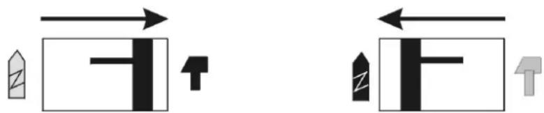
Put the mode selector (13) on „Drilling“ and the Rotational Direction Switch (10) on „Right“. Select the speed with button (11).
Stone and Concrete Drilling
Put the mode selector (13) on „Impact“ and the Rotational Direction Switch (10) on „Right“. Select the speed with button (11) and start with low speed.
Driving Screws
Put the mode selector on "Drilling" and the Rotational Direction Switch (10) on „Right" for screwing up and Left for screwing out. Select the speed with button (11) and start with low speed.
Operator Safety Instructions
- Do not use the machine until you have read the instruction manual carefully.
- Observe any safety instructions included in the manual.
• Be responsible to the others
Inspections and Maintenance
The machine does not require any special maintenance. The repairs should be done by professionals only using genuine parts. Clean the body with a wet cloth only – do not use solvents! Dry well afterwards.
Inspections and Maintenance Safety Instructions
The machine will serve as a sufficient aid only if maintained and care for appropriately. Insufficient maintenance and care may result in accidents and injuries.

Obr. 1
Obr. 1
- Príklepová vřtačka
- Aretačný gombík
- Prípojný kábel
- Vrtáky na ocel'
- Vrtáky na drevo
- Vrtáky na kameň
- Rýchloupínacie skľučovadlo
- Prídavná rukovát'
- Zarážka pre híbku vítania
- Prepínač režimov „doľava/doprava“
- Regulátor otáčok
- Spínač zapnuté/vypnuté
- Prepínač režimov „vítanie/kladivo“
Záruka
Fig. 1
Fig. 1
Slika 1
EC-DECLARATION OF CONFORMITY
We, hereby declare the conception and construction of the belowmentioned appliances correspond - at the type of construction being launched - to appropriate basic safety and hygienic requirements of EC Directives. In case of any change to the appliance not discussed with us the Declaration expires.
PROHLÁŠENÍ O SHODĚ EU
DECLARATION CE DE CONFORMITÉ
2006/42/EC, 2004/108/EC
Schlagbohrmaschine • Impact Drill • Príklepová Vrtačka • Udarna Bušilica • Príklepová Vrtačka • Perceuse A Percussion • Slagboormachine • Trapano A Percussione • Vrtalni Stroj Z Udarno Funkcijo
BX 710
Angewandte harmonisierte Normen • Applicable harmonized Standard • Použité harmonizované normy • Primijenjene harmonizirane norme • Použité harmonizované normy • Normes harmonisées Applicables • Gebruikte harmoniserende normen • Applicate norme armonizzate • Uporabljeni usklajeni standardi
EN 60745-1:2009, EN 60745-2-1:2003+A11:07+A1:09+A12:09, EN 55014-1:2006, EN 55014-2:1997/+A1:2001, EN 61000-3-2:2006, EN 61000-3-3:1995/+A1:2001/+A2:2005
Güde GmbH & Co. KG

- Warranty
- General Safety Instructions
- FOLLOW THE INSTRUCTIONS BELOW CAREFULLY IN ORDER TO SECURE A HIGH DEGREE OF SAFETY:
- CAUTION!
- Safe Work
- CAUTION
- Emergency Action
- Signs on Unit
- Meaning of Symbols
- Assigned Use
- Disposal
- Disposal of transport packaging
- Operator Requirement
- Qualification
- Minimum Age
- Training
- Technical Data
- Initial Operation Safety Instructions
- Operation
- Wood and Metal Drilling
- Stone and Concrete Drilling
- Driving Screws
- Operator Safety Instructions
- Inspections and Maintenance
- Inspections and Maintenance Safety Instructions
- Záruka
- EC-DECLARATION OF CONFORMITY
- PROHLÁŠENÍ O SHODĚ EU
- DECLARATION CE DE CONFORMITÉ
Brand : Güde
Model : BX 710
Category : Drill