
PC932AW - Flat screen mount Peerless-AV - Free user manual and instructions
Find the device manual for free PC932AW Peerless-AV in PDF.
| Product Type | Flat Screen Mount |
| Brand | Peerless-AV |
| Model | PC932AW |
| Screen Compatibility | 15 to 40 inches |
| Maximum Load Capacity (UL standard) | 80 lb (36.3 kg) |
| Compatible VESA Standards | 75 x 75 mm, 100 x 100 mm, 200 x 100 mm, 200 x 200 mm |
| Adjustable Extension | 9.8 - 13.9 in (249 - 353 mm) |
| Adjustable Tilt | +20° / -5° |
| Rotation | 360° (during installation) |
| Lateral Pivot | ±3° |
| Orientation | ±45° |
| Cable Management | Internal cable management system |
| Material | Steel |
| Finish | White |
| Mounting Type | Ceiling |
| Recommended Mounting Surface | Wood joists, solid concrete, hollow concrete block |
| Usage | Indoor only |
| Warranty | 5-year limited |
| Package Contents | Ceiling plate, outer rail, inner rail, clamping plate, swivel bracket, tilt bracket, cable conduits, hardware, anchors, hex key |
| Maintenance | Clean with a soft, dry cloth |
| Safety | Do not exceed maximum load; installation by a qualified professional recommended |
Frequently Asked Questions - PC932AW Peerless-AV
User questions about PC932AW Peerless-AV
0 question about this device. Answer the ones you know or ask your own.
Ask a new question about this device
Download the instructions for your Flat screen mount in PDF format for free! Find your manual PC932AW - Peerless-AV and take your electronic device back in hand. On this page are published all the documents necessary for the use of your device. PC932AW by Peerless-AV.
USER MANUAL PC932AW Peerless-AV
Installation and Assembly: Ceiling Mount for 15" - 40" Flat Panel Displays
| Models | Screen Size Range Max UL Load Capacity |
| PC930A, PC930A-S, PC930A-W, PC930B, PC930B-S, PC930B-W, PC930C, PC930C-S, PC930C-W | 15" to 24" 50 lb (22.7 kg) |
| PC932A, PC932A-S, PC932A-W, PC932B, PC932B-S, PC932B-W, PC932C, PC932C-S, PC932C-W | 15" to 40" 80 lb (36.3 kg) |

Features:
- VESA® 75/100/200x100/200x200 compatible
Three adjustable extension lengths: PC930A/PC932A models - 9.8" - 13.9" PC930B/PC932B models - 13.78" - 21.89" PC930C/PC932C models - 20.24" - 34.02"
Adjustable tilt of +20 / - 5^
360^ of mountable adjustment - Internal cable management
- Safety catch designed into extension channels to ensure user and equipment safety
WARNING
- Do not begin to install your Peerless product until you have read and understood the instructions and warnings contained in this Installation Sheet. If you have any questions regarding any of the instructions or warnings, for US customers please call Peerless customer care at 1-800-865-2112, for all international customers, please contact your local distributor.
- This product should only be installed by someone of good mechanical aptitude, has experience with basic building construction, and fully understands these instructions.
- Make sure that the supporting surface will safely support the combined load of the equipment and all attached hardware and components.
- Never exceed the Maximum UL Load Capacity. See page one.
- If mounting to wood ceiling studs, make sure that mounting screws are anchored into the center of the studs. Use of an "edge to edge" stud fi nder is highly recommended.
- Always use an assistant or mechanical lifting equipment to safely lift and position equipment.
- Tighten screws firmly, but do not overtighten. Overtightening can damage the items, greatly reducing their holding power.
This product is intended for indoor use only. Use of this product outdoors could lead to product failure and personal injury. - This product was designed to be installed on the following ceiling construction only;
CEILING CONSTRUCTION HARDWARE REQUIRED
Wood Stud, Joist Included
Wood Beam Included
Solid Concrete Included
Cinder Block Contact Qualified Professional
- Metal Stud Do not attach except with Peerless accessory kit for metal studs; Contact Customer Service for Peerless accessory kit for metal studs. (not evaluated by UL)
- Brick Contact Qualified Professional (not evaluated by UL)
Other or unsure? Contact Qualified Professional
Tools Needed for Assembly
- stud fi nder ("edge to edge" stud fi nder is recommended)
-
drill
level -
5/16" bit for concrete
- 5/32" bit for wood joist
- phillips screwdriver
Table of Contents
Parts List. 3, 4
Install Outer Channel to Ceiling Plate. 4
Installation to Wood Joist. 5
Installation to Concrete Ceilings 6
7
Attaching Mounting Plate to Display with VESA 75 or 100 Mounting Pattern 8
Attaching Adapter Plate to Display with VESA 200 x 100 or 200 x 200 Mounting Pattern
Installing Flat Panel Display 10
Adjusting Mount Extension 10
Adjusting Display 11
Install Cable Covers 11
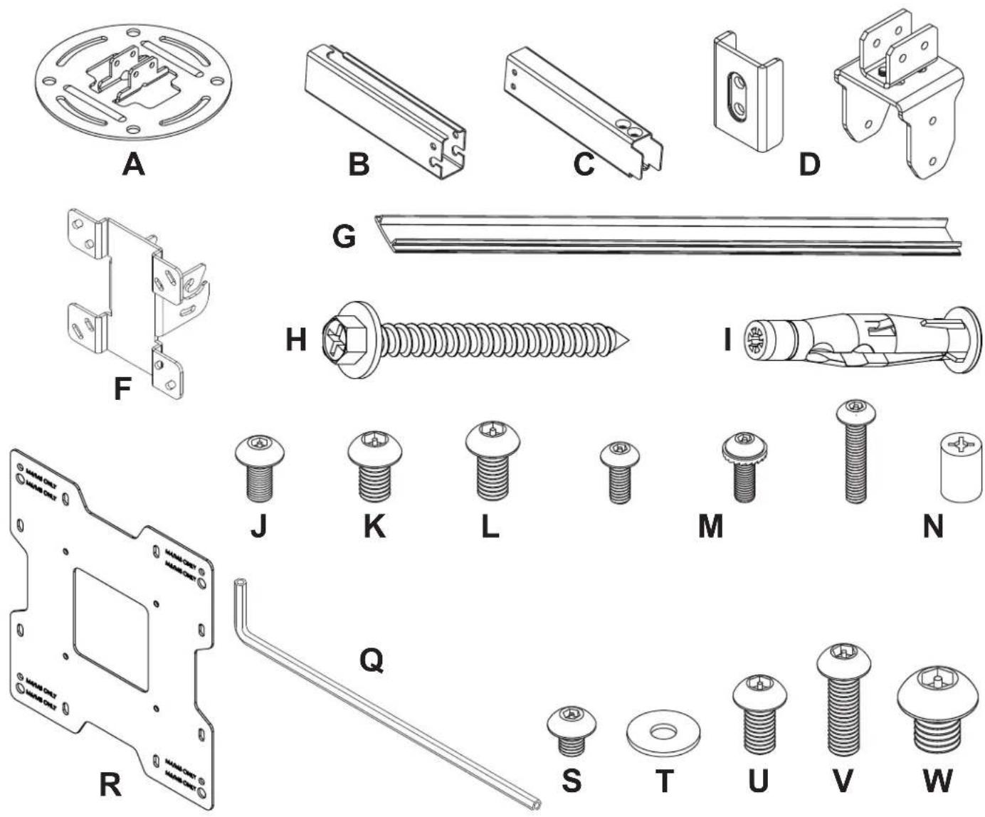
Before you begin, make sure all parts shown are included with your product.
| Parts ListDescription Qty. | PC930A,PC930B,PC930C Part # Part # Part # Part # Part # Part # | PC930A-S,PC930B-S,PC930C-S | PC930A-W,PC930B-W,PC930C-W | PC932A,PC932B,PC932C | PC932A-S,PC932B-S,PC932C-S | PC932A-W,PC932B-W,PC932C-W | |
| A ceiling plate 1 055-1773 055-4773 055-2773 055-1773 055-4773 055-2773 | |||||||
| B outer channel 1 See Chart See Chart See Chart See Chart See Chart See Chart | |||||||
| C inner channel 1 See Chart See Chart See Chart See Chart See Chart See Chart | |||||||
| D clamp plate 1 055-1771 055-4771 055-2771 055-1771 055-4771 055-2771 | |||||||
| E swivel/pivot bracket 1 055-1811 055-4811 055-2811 055-1811 055-4811 055-2811 | |||||||
| F tilt bracket 1 095-1484 095-4484 095-2484 095-1484 095-4484 095-2484 | |||||||
| G cable cover 2 See Chart See Chart See Chart See Chart See Chart See Chart | |||||||
| H #14 x 2.5 wood screw | 2 | 5S1-015-C03 | 5S1-015-C04 | 5S1-015-C04 | 5S1-015-C03 | 5S1-015-C04 | 5S1-015-C04 |
| I concrete anchor | 2 | 590-0320 | 590-0320 | 590-0320 | 590-0320 | 590-0320 | |
| J M5 x 10 mm socket pin screw | 8 | 520-1063 | 520-2063 | 520-2063 | 520-1063 | 520-2063 | |
| K M6 x 10 mm socket pin screw | 4 | 520-1066 | 520-2066 | 520-2066 | 520-1066 | 520-2066 | |
| L M6 x 12 mm socket pin screw | 2 | 520-1050 | 520-2050 | 520-2050 | 520-1050 | 520-2050 | |
| M M4 x 10 mm socket pin screw | 4 | 520-1060 | 520-2060 | 520-2060 | 520-1060 | 520-2060 | |
| N M4 x 12 mm socket pin serratedwasher head screw | 4 | 510-1079 | 510-2079 | 510-2079 | 510-1079 | 510-2079 | |
| O M4 x 20 mm socket pin screw | 4 | 520-1061 | 520-2163 | 520-2163 | 520-1061 | 520-2163 | |
| P retaining spacer | 4 | 590-5005 | 590-5005 | 590-5005 | 590-5005 | 590-5005 | |
| Q 4 mm security allen wrench | 1 | 560-9646 | 560-9646 | 560-9646 | 560-9646 | 560-9646 | |
| R adapter plate | 1 | N/A | N/A | N/A | 095-1721 | 095-4721 | 095-2721 |
| S M5 x 6 mm socket pin screw | 4 | N/A | N/A | N/A | 520-1114 | 520-2062 | 520-2062 |
| T #10 flat washer | 4 | N/A | N/A | N/A | 540-9400 | 540-9442 | 540-9442 |
| U M6 x 12 mm socket pin screw | 4 | N/A | N/A | N/A | 520-1050 | 520-2050 | 520-2050 |
| V M6 x 20 mm socket pin screw | 4 | N/A | N/A | N/A | 520-9554 | 520-2554 | 520-2554 |
| W M8 x 10 mm socket pin screw | 4 | N/A | N/A | N/A | 520-1706 | 520-2706 | 520-2706 |
Parts may appear slightly different than illustrated.
OUTER CHANNEL, INNER CHANNEL AND CABLE COVER PART NUMBER CHART
| Model# | extendable length | outer channel (B) part # | inner channel (C) part # | cable cover (G) part # |
| PC930A, PC932A | 9.8" - 13.9" | 055-1779 | 055-1778 | 055-1809-2 |
| PC930A-S, PC932A-S | 9.8" - 13.9" | 055-4779 | 055-4778 | 055-4809-2 |
| PC930A-W, PC932A-W | 9.8" - 13.9" | 055-2779 | 055-2778 | 055-2809-2 |
| PC930B, PC932B | 13.78" - 21.89" | 055-1776 | 055-1775 | 055-1809-1 |
| PC930B-S, PC932B-S | 13.78" - 21.89" | 055-4776 | 055-4775 | 055-4809-1 |
| PC930B-W, PC932B-W | 13.78" - 21.89" | 055-2776 | 055-2775 | 055-2809-1 |
| PC930C, PC932C | 20.24" - 34.02" | 055-1770 | 055-1769 | 055-1809 |
| PC930C-S, PC932C-S | 20.24" - 34.02" | 055-4770 | 055-4769 | 055-4809 |
| PC930C-W, PC932C-W | 20.24" - 34.02" | 055-2770 | 055-2769 | 055-2809 |
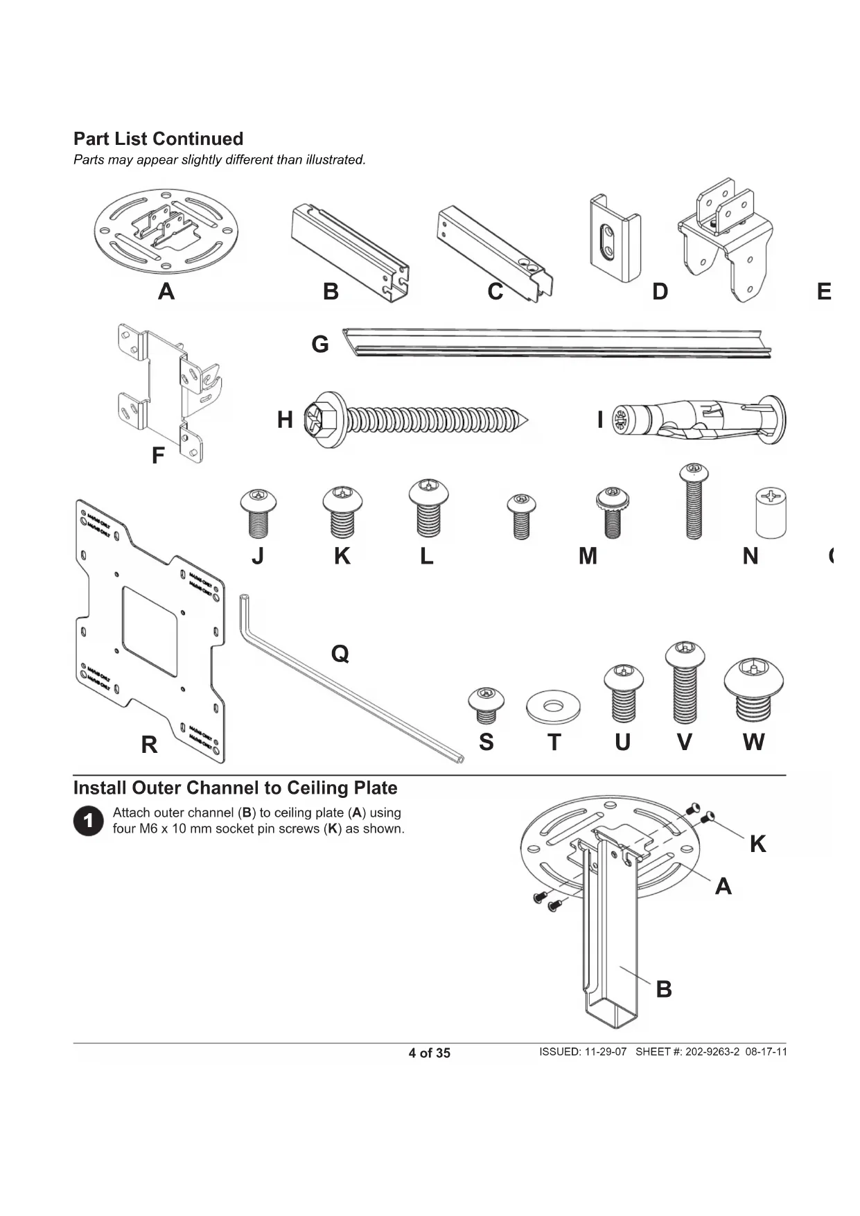
Part List Continued
Parts may appear slightly different than illustrated.
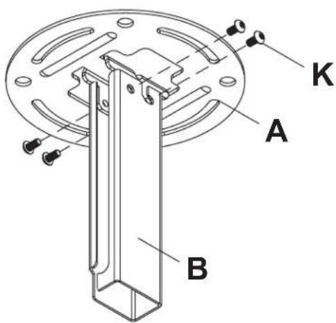
Install Outer Channel to Ceiling Plate

Attach outer channel (B) to ceiling plate (A) using four M6 x 10 mm socket pin screws (K) as shown.
Installation to Wood Joist Ceilings
WARNING
- Installer must verify that the supporting surface will safely support the combined load of the equipment and all attached hardware and components.
- Tighten wood screws so that ceiling plate is firmly attached, but do not overtighten. Overtightening can damage the screws, greatly reducing their holding power.
- Never tighten in excess of 80 in. - Ib (9 N.M.).
- Make sure that mounting screws are anchored into the center of the stud or joist. The use of an "edge to edge" stud fi nder is highly recommended.
- Hardware provided is for attachment of mount through standard thickness drywall or plaster into wood studs or joists. Installers are responsible to provide hardware for other types of mounting situations (not evaluated by UL).

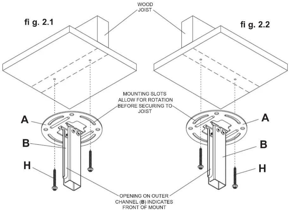
Use a stud fi nder to locate the edges of the joist. Use of an edge-to-edge stud fi nder is highly recommended. Based on its edges, draw a vertical line down the joist's center. Place ceiling plate (A) on ceiling as a template, making sure that the two mounting slots are on the stud centerline.
Note: Opening on outer channel (B) indicates front of mount. Use the correct mounting slots on the ceiling plate depending on ceiling joist orientation as shown in figure 2.1 or figure 2.2. Mounting slots on ceiling plate allow for 45^ ( ± 22.5 ) of swivel adjustment before securing to joist.
Mark the center of the two mounting holes depending on joist orientation as shown in fi gure 2.1 or fi gure 2.2. Drill two 5 / 32'' (4 mm) dia. holes 2 - 1 / 2'' (65 mm) deep. Secure ceiling plate (A) to wood joist using two #14 x 2-1/2" wood screws (H) as shown.
Skip to step 3.
Installation to Concrete Ceilings
WARNING
Concrete must be 2000 psi density minimum. Lighter density concrete may not hold concrete anchor.
- Make sure that the supporting surface will safely support the combined load of the equipment and all attached hardware and components.

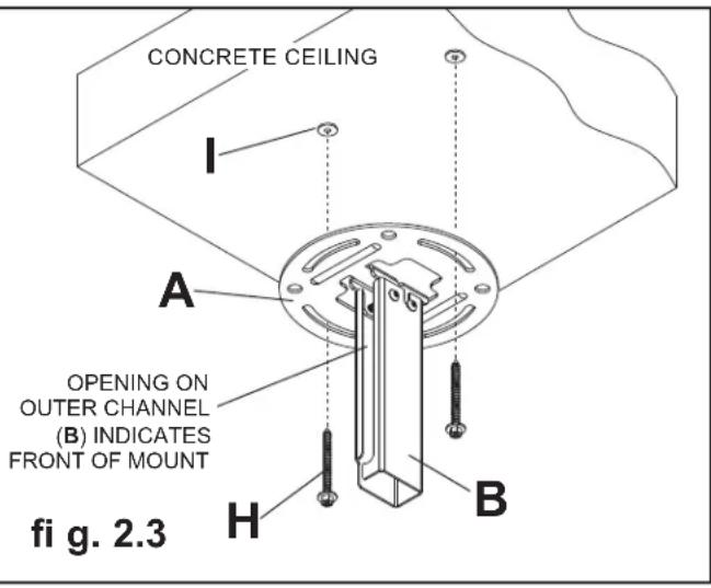
Place ceiling plate (A) on ceiling as a template and mark the center of the two mounting holes.
Note: Opening in outer channel indicates the front of the mount.
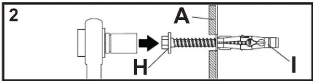
Drill two 5 / 16'' (8 mm) dia. holes to a minimum depth of 2.5'' (64 mm). Attach ceiling plate (A) using two concrete anchors (I) and two #14 x 2.5" wood screws (H) as shown in figure 2.3. Tighten wood screws (H) until ceiling plate (A) is firmly attached.
WARNING
- Tighten wood screws firmly, but do not overtighten. Overtightening can damage the screws, greatly reducing their holding power.
- Never tighten in excess of 80 in · Ib (9 N.M.)
WARNING
- Always attach concrete expansion anchors directly to load-bearing concrete.
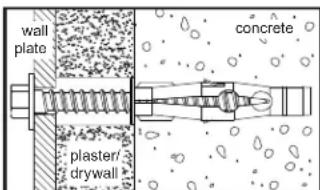
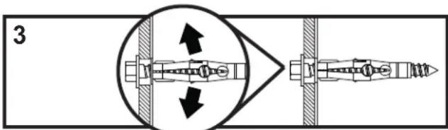
- Never attach concrete expansion anchors to concrete covered with plaster, drywall, or other fi nishing material. If mounting to concrete surfaces covered with a fi nishing surface is unavoidable (not evaluated by UL), the fi nishing surface must be counterbored as shown below. Be sure concrete anchors do not pull away from concrete when tightening screws. If plaster/drywall is thicker than 5/8'' (16 mm), custom fasteners must be supplied by installer (not evaluated by UL).

INCORRECT CORRECT
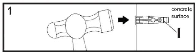
Drill holes and insert anchors (I).
Place plate (A) over anchors (I) and secure with screws (H).
Tighten all fasteners.
Installing Inner Channel and Routing Cables

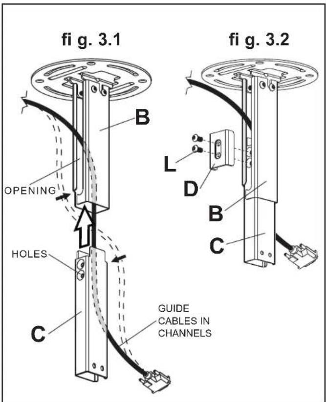
Note: Be certain holes on inner channel (C) face in the same direction of opening on outer channel (B).
Note: Cables must be removed from display before routing through channels. If cables are not removable from display, routing through channels is not an option.
Guide display cables into openings in channels then insert inner channel (C) into outer channel (B) as shown in figure 3.1.
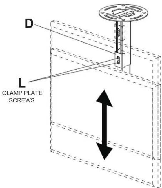
Position inner channel (C) to the desired height and secure using two M6 x 12 mm socket pin screws (L) through clamp plate (D), through opening in outer channel (B) and into inner channel (C) as shown in figure 3.2.

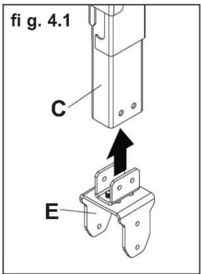
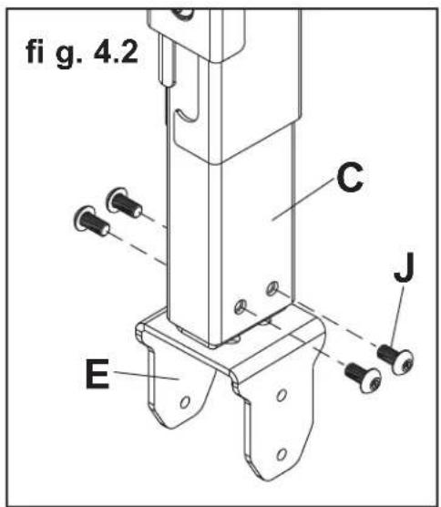
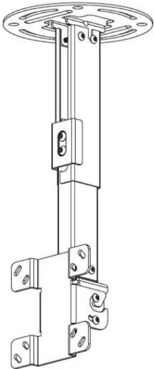
Insert swivel/pivot bracket (E) into end of inner channel (C) and secure with four M5 x 10 mm socket pin screws (J) as shown in fi gure 4.1 and fi gure 4.2.
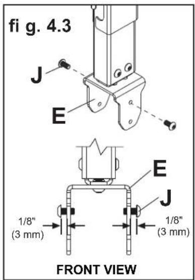
Thread two M5 x 10 mm screws (J) into top holes of swivel/pivot bracket (E), leaving 1/8'' (3 mm) exposed thread between head of screw and swivel/pivot bracket as shown in figure 4.3.
CABLES NOT SHOWN FOR CLARITY
Attaching Mounting Plate to Display with VESA 75 or 100 Mounting Pattern
Note: For VESA 200 × 100 ~mm and 200 × 200 ~mm hole patterns, see following page.
WARNING
- If screws don't get three complete turns in the display inserts or if screws bottom out and bracket is still not tightly secured, damage may occur to display or product may fail.

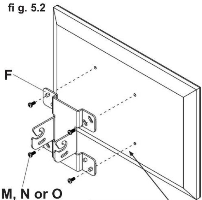
Choose hole pattern as shown in fi gure 5.1 which matches hole pattern on back of your display. Attach tilt bracket (F) to back of display using four M4 x 10 mm screws (M) or M4 x 12 mm screws (N) as shown in figure 5.2.
*NOTE: If hole pattern is in a pocket, attach tilt bracket (F) to back of display using four M4 x 20 mm screws (O) and four retaining spacers (P) as indicated in fi gure 5.2.
Skip to step 6.
fig. 5.1
FOR VESA 75 MOUNTING PATTERN:
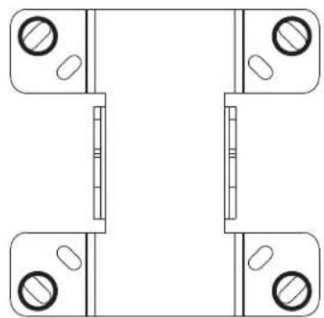
FOR VESA 100 MOUNTING PATTERN:
*For displays with a hole pattern in a pocket, spacers go between tilt bracket and display when used with M4 x 20 mm screws (O).
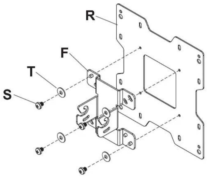
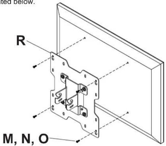
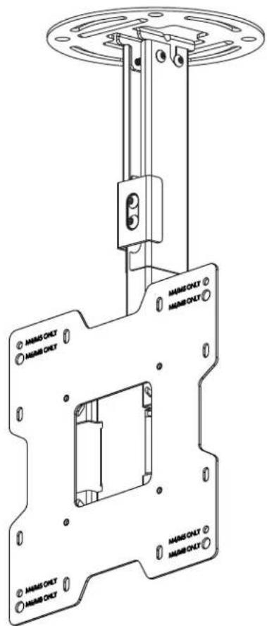
Attaching Adapter Plate to Display with VESA 200 or 200× 100 Mounting Pattern

Attach tilt bracket (F) onto adapter plate (R) using four M5 x 6 mm screws (S) and #10 washers (T) as shown.
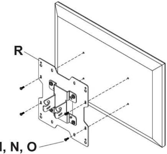
FOR VESA 200 x 100 MOUNTING PATTERN:

Choose hole pattern as shown below. Attach adapter plate (R) to back of display using four M4 screws (M, N, O) as shown below.
WARNING
- If screws don't get three complete turns in the display inserts or if screws bottom out and bracket is still not tightly secured, damage may occur to display or product may fail.
FOR VESA 200 MOUNTING PATTERN USING M4 SCREWS:
Choose hole pattern as shown below. Attach adapter plate (R) to back of display using four M4 screws (M or N) as shown below.
NOTE: If screw (M or N) gets less than three threads of engagement, attach adapter plate (R) to back of display using four M4 x 20 mm screws (O) and four spacers (P) as indicated below.
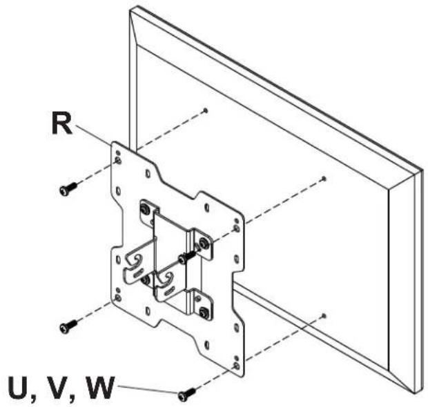
FOR VESA 200 MOUNTING PATTERN USING M6 OR M8 SCREWS:
Choose hole pattern as shown below. Attach adapter plate (R) to back of display using four M6 or M8 screws (U, V, W) as shown below.
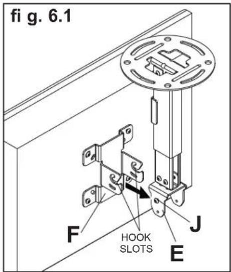
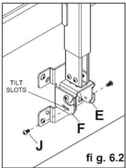
Attaching Display

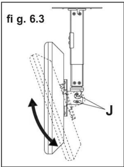
Guide hook slots of tilt bracket (F) onto M5 x 10 mm screws (J) in swivel/pivot bracket (E) as shown in figure 6.1. Thread two M5 x 10 mm screws (J) through tilt slot of tilt bracket (F) into swivel/pivot bracket (E) as shown in figure 6.2. Do not fully tighten screws to allow for tilt adjustments. Tilt slot allows for incremental tilts of 5^ . Adjust tilt of display and fully tighten all four M5 x 10 mm screws (J) as shown in figure 6.3.
WARNING
- Do not lift more weight than you can handle. Use additional man power or mechanical lifting equipment to safely handle placement of the display.
Adjusting Mount Extension

While supporting the weight of the display, loosen screws (L) on clamp plate (D) half a turn and position display to the desired height. Retighten clamp plate screws securely.
WARNING
- Clamp plate adjustment screws support weight of display when fully tightened. Weight of the display will need to be supported if clamp plate screws are loosened.
Adjusting Display

If screws indicated are fully tightened, loosen screws half a turn to allow for adjusting tilt, swivel and roll. Adjust display to the desired position and fully tighten screws.
WARNING
- Do not loosen adjustment screws to the point they become disengaged from the mount. Weight of the display should be supported in case of accidental disengagement.
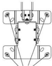
ROLL ADJUSTMENT BACK VIEW
SCREWS FOR ROLL ADJUSTMENT
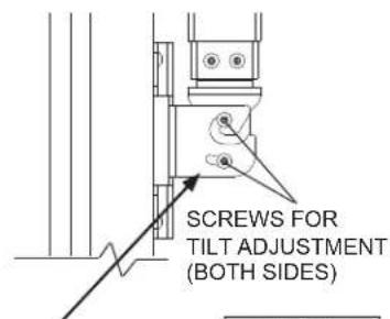
TILT ADJUSTMENT SIDE VIEW
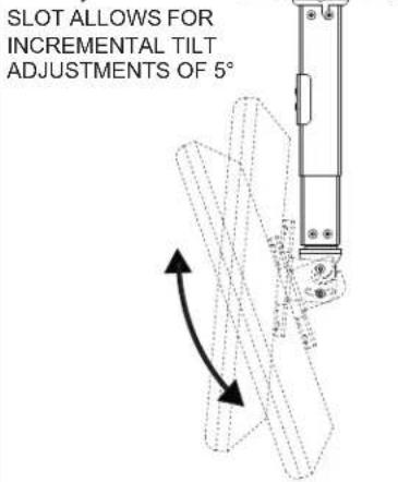
25^ (+20^ / -5^) TILT
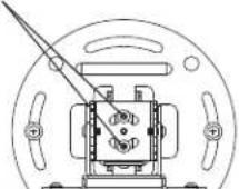
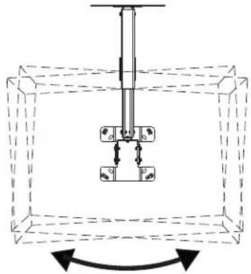
SWIVEL ADJUSTMENT BOTTOM VIEW
SCREWS FOR SWIVEL ADJUSTMENT
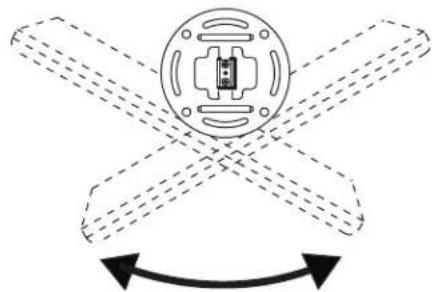
90^(± 45^) SWIVEL6 (± 3^) ROLL
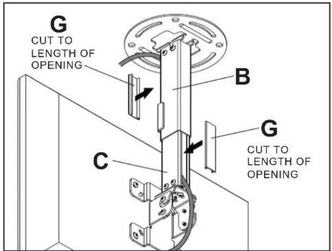
Install Cable Covers

NOTE: Be certain mount is in the desired extended position.
Attach cables to display if routed through channels.
Cut cable covers (G) to the length of inner channel (C) and outer channel (B) openings, leaving space for cables if routed through channels. Snap cable covers into openings as shown.
Cables not routed through channels will require cable ties (not included).
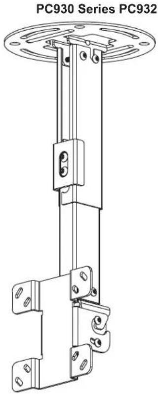
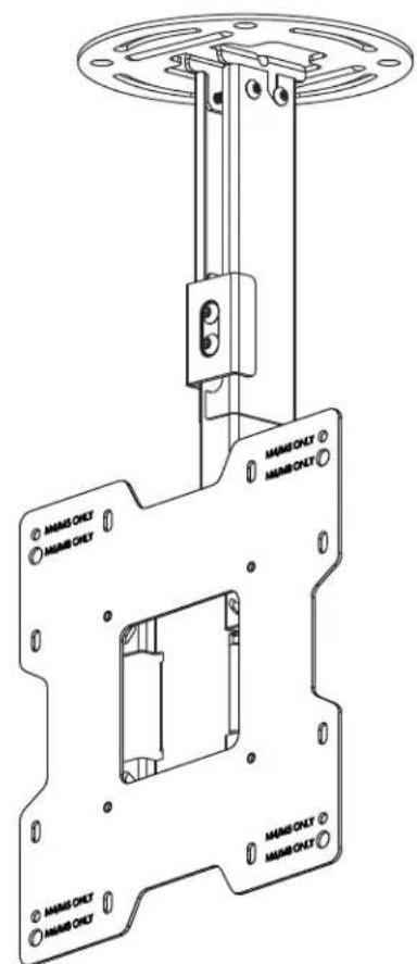
PC930 Series PC932 Series
\section*{Caracteristiques}
Peerless Industries, Inc. ("Peerless") warrants to original end-users of Peerless® products will be free from defects in material and workmanship, under normal use, for a period of five years from the date of purchase by the original end-user (but in no case longer than six years after the date of the product's manufacture). At its option, Peerless will repair or replace, or refund the purchase price of, any product which fails to conform with this warranty.
In no event shall the duration of any implied warranty of merchantability or fitness for a particular purpose be longer than the period of the applicable express warranty set forth above. Some states do not allow limitations on how long an implied warranty lasts, so the above limitation may not apply to you.
This warranty does not cover damage caused by (a) service or repairs by the customer or a person who is not authorized for such service or repairs by Peerless, (b) the failure to utilize proper packing when returning the product, (c) incorrect installation or the failure to follow Peerless' instructions or warnings when installing, using or storing the product, or (d) misuse or accident, in transit or otherwise, including in cases of third party actions and force majeure.
In no event shall Peerless be liable for incidental or consequential damages or damages arising from the theft of any product, whether or not secured by a security device which may be included with the Peerless® product. Some states do not allow the exclusion or limitation of incidental or consequential damages, so the above limitation or exclusion may not apply to you.
This warranty is in lieu of all other warranties, expressed or implied, and is the sole remedy with respect to product defects. No dealer, distributor, installer or other person is authorized to modify or extend this Limited Warranty or impose any obligation on Peerless in connection with the sale of any Peerless® product.
This warranty gives specific legal rights, and you may also have other rights which vary from state to state.
peerless-AV
www.peerlessmounts.com
© 2011 Peerless Industries, Inc.
Espanol
GARANTÍA LIMITADA DE CINCO ANOS
www.peerlessmounts.com
© 2011 Peerless Industries, Inc.
GARANTIE DE CINQ ANS
www.peerlessmounts.com
© 2011 Peerless Industries, Inc.


- Installation and Assembly: Ceiling Mount for 15" - 40" Flat Panel Displays
- Features:
- WARNING
- CEILING CONSTRUCTION HARDWARE REQUIRED
- Tools Needed for Assembly
- Table of Contents
- Part List Continued
- Install Outer Channel to Ceiling Plate
- Installation to Wood Joist Ceilings
- Installation to Concrete Ceilings
- Installing Inner Channel and Routing Cables
- Attaching Mounting Plate to Display with VESA 75 or 100 Mounting Pattern
- Attaching Adapter Plate to Display with VESA 200 or 200× 100 Mounting Pattern
- FOR VESA 200 x 100 MOUNTING PATTERN:
- WARNING
- FOR VESA 200 MOUNTING PATTERN USING M4 SCREWS:
- FOR VESA 200 MOUNTING PATTERN USING M6 OR M8 SCREWS:
- Attaching Display
- Adjusting Mount Extension
- Adjusting Display
- Install Cable Covers
- \section*{Caracteristiques}
- GARANTÍA LIMITADA DE CINCO ANOS
- GARANTIE DE CINQ ANS
Brand : Peerless-AV
Model : PC932AW
Category : Flat screen mount