
ECMU02IS - Flat screen mount Peerless-AV - Free user manual and instructions
Find the device manual for free ECMU02IS Peerless-AV in PDF.
| Product Type | Outdoor Flat Panel Mount |
| Brand | Peerless-AV |
| Model | ECMU02IS |
| Screen Compatibility | 32 to 65 inches |
| Maximum Load Capacity | 90.7 kg (200 lb) |
| Wind Resistance | 145 km/h (90 mph), Category D, maximum altitude 60 m (200 ft) |
| Usage | Outdoor only |
| Mounting | I-beam |
| Tilt Adjustment | From -5° to +15° (5 pre-set positions via IncreLok device) |
| Material | Steel |
| Safety Cable Included | Yes, 5 in. metal cable with cable clips |
| Warranty | 5 years material and workmanship defects, 1 year against corrosion |
| VESA Standards | Compatible with M6 and M8 screws (multiple lengths) |
| Required Tools | Phillips screwdriver, 3/16" hex key, level |
| Maintenance | Annual inspection and after high winds |
Frequently Asked Questions - ECMU02IS Peerless-AV
User questions about ECMU02IS Peerless-AV
0 question about this device. Answer the ones you know or ask your own.
Ask a new question about this device
Download the instructions for your Flat screen mount in PDF format for free! Find your manual ECMU02IS - Peerless-AV and take your electronic device back in hand. On this page are published all the documents necessary for the use of your device. ECMU02IS by Peerless-AV.
USER MANUAL ECMU02IS Peerless-AV
Installation and Assembly:
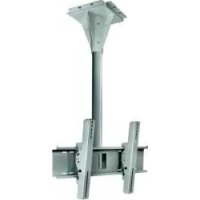
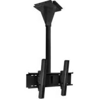
Wind Rated I-beam Tilt Mount for 32" - 65" Outdoor Flat Panel Displays
Models: ECMU-01-I, ECMU-01-I-S, ECMU-02-I, ECMU-02-I-S, ECMU-03-I, ECMU-03-I-S, ECMU-04-I, ECMU-04-I-S
natural_image
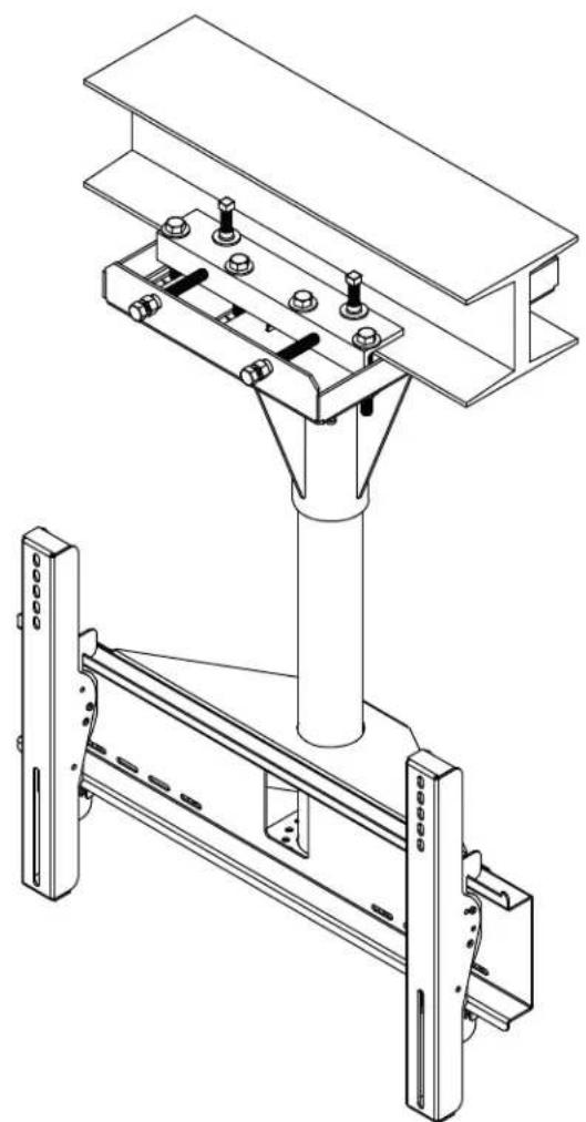
Technical line drawing of a mechanical assembly with two views: top shows a beam supported by bolts, bottom shows a structural frame with supports (no text or symbols)

Max UL Load Capacity: 200 lb (90.7 kg)
Max Wind Rating: 90 mph, elevation 200 ft, Category D
WARNING
- Do not begin to install your Peerless product until you have read and understood the instructions and warnings contained in this Installation Sheet. If you have any questions regarding any of the instructions or warnings, for US customers please call Peerless customer care at 1-800-865-2112, for all international customers, please contact your local distributor.
- Due to outdoor environmental conditions such as strong wind gusts, heavy snow, hail, rain, etc. The environmental enclosure, together with its mount, extension tube and hardware, must be inspected at least once a year, and immediately following any time winds exceed 90 mph. A qualified installer or inspector must check for signs of rust, loose fasteners, bent metal, etc. If evidence of excessive wear, deterioration or any unsafe condition is observed, this product must be taken out of service immediately. Direct all inquiries to customer care if you have any questions.
- This product should only be installed by someone of good mechanical aptitude, has experience with basic building construction, and fully understands these instructions.
- Make sure that the supporting surface will safely support the combined load of the equipment and all attached hardware and components.
- Never exceed the Maximum UL Load Capacity. See page one.
- If mounting to wood wall studs, make sure that mounting screws are anchored into the center of the studs. Use of an "edge to edge" stud fi nder is highly recommended.
• Always use an assistant or mechanical lifting equipment to safely lift and position equipment. - Tighten screws firmly, but do not overtighten. Overtightening can damage the items, greatly reducing their holding power.
• This product was designed for use with other outdoor products only.
Tools Needed for Assembly
• phillips screwdriver, 3/16" allen wrench
- level
Table of Contents
Parts List....3
Installation to I-beam 4
Installing Tilt Brackets....7
Mounting and Removing Flat Panel Screen....8
Before you begin, make sure all parts shown are included with your product.
| Parts List | ECMU-01-I | ECMU-01-I-S | |
| ECMU-02-I | ECMU-02-I-S | ||
| ECMU-03-I | ECMU-03-I-S | ||
| ECMU-04-I | ECMU-04-I-S | ||
| Description Qty. Part # Part # Model # Part # | |||
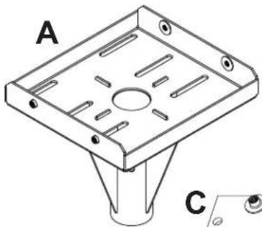
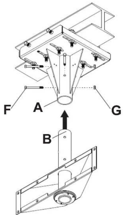
| A | ceiling plate | 1 | 061-T1283 061-7283 |
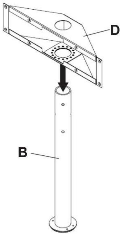
| B | support column | 1 | see chart see chart |
| C | ceiling clamp | 2 | 061-T1281 061-7281 |
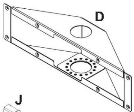
| D | adapter box | 1 | 061-T1264 061-7264 ECMU-02-I-S |
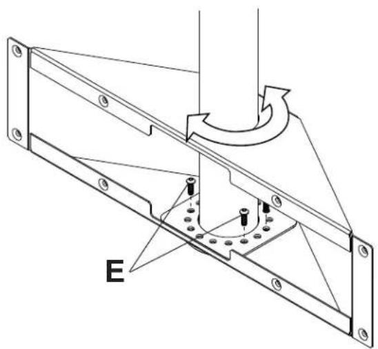
| E | 5/16"-18 x 1" socket screw | 4 | 520-5035 520-5035 |
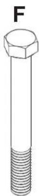
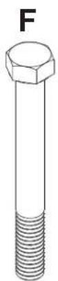
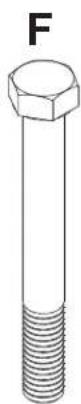
| F | 7/16" x 4" hex head bolt 3 | 520-5014 520-5014 | |
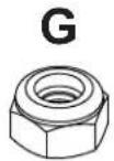
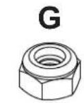
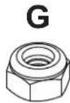
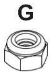
| G | 7/16" nylock nut | 3 | 530-5003 530-5003 |
| H | adapter plate | 1 | 061-T1258 061-7258 ECMU-04-I-S |
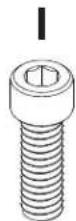
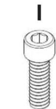
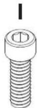
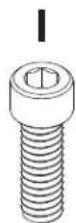
| I | 1/4-20 x .75" socket screw | 8 | 520-5034 520-5034 |
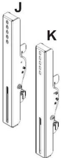
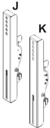
| J | left tilt bracket 1 061-T1383 061-7383 | ||
| K | right tilt bracket | 1 | 061-T1382 061-7382 |
| L | security allen wrench | 1 | 560-9646 560-9646 |
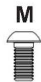
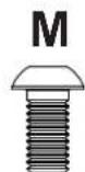
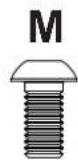
| M | M6 x 12 mm socket pin screw | 4 | 520-5023 520-5023 |
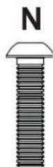
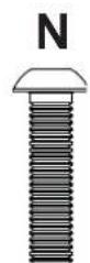
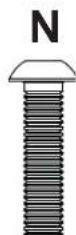
| N | M6 x 25 mm socket pin screw | 4 | 520-5024 520-5024 |
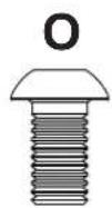
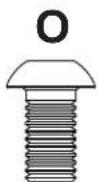
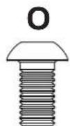
| O | M8 x 15 mm socket pin screw | 4 | 520-5026 520-5026 |
| P | M6 x 20 mm socket pin screw | 4 | 520-5025 520-5025 |
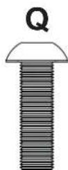
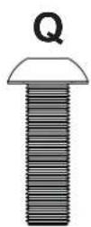
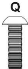
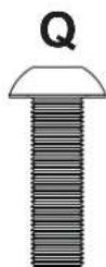
| Q | M8 x 25 mm socket pin screw | 4 | 520-5027 520-5027 |
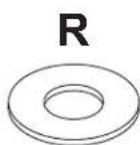
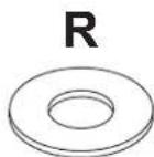
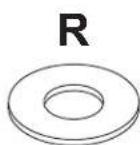
| R | washer | 4 | 540-5014 540-5014 |
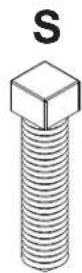
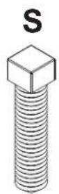
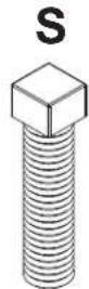
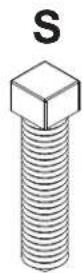
| S | 1/2-13 x 2" square head screw | 4 | 520-5036 520-5036 |
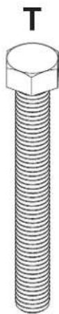
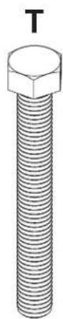
| T | 1/2-13 x 4" bolt | 12 | 520-5019 520-5019 |
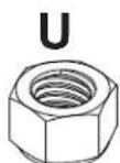
| U | 1/2-13 nylock nut | 8 | 530-5005 530-5005 |
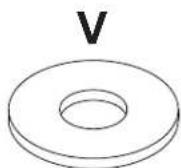
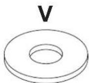
| V | 1/2" washer | 16 | 540-5010 540-5010 |
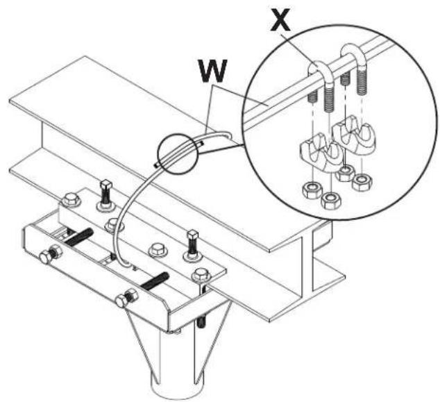
| W | 5' wire rope (not shown) | 1 | 560-0056 560-0056 |
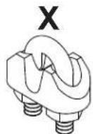
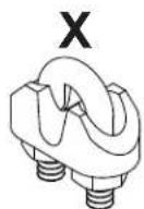
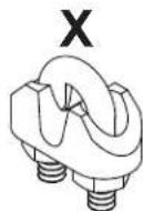
| X | cable clip | 2 | 560-0069 560-0069 |
| Y | 1/2-13 hex nut | 4 | 530-5010 530-5010 |
| Support Column (B) |
| ECMU-01-I 061-T1266 |
| ECMU-01-I-S 061-7266 |
| ECMU-02-I 061-T1267 |
| 1-7267 |
| ECMU-03-I 061-T1268 |
| ECMU-03-I-S 061-7268 |
| ECMU-04-I 061-T1269 |
| 1-7269 |
B
natural_image
Technical line drawing of a mechanical component with labeled points A and C (no text or symbols beyond labels)
Parts may appear slightly different than illustrated.
natural_image
Technical line drawing of a mechanical bracket with mounting holes and a central circular feature (no text or symbols)


natural_image
Two identical 3D illustrations of a vertical device with labeled ports (J and K), showing internal components and wiring (no text or symbols beyond labels)
natural_image
Technical line drawing of a structural beam with supports and a labeled section H (no text or symbols beyond label)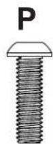


L
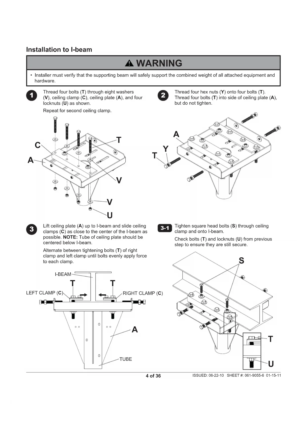
Installation to I-beam
WARNING
• Installer must verify that the supporting beam will safely support the combined weight of all attached equipment and hardware.
1
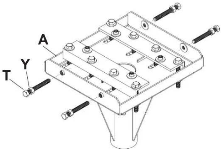
Thread four bolts (T) through eight washers (V), ceiling clamp (C), ceiling plate (A), and four locknuts (U) as shown.
Repeat for second ceiling clamp.
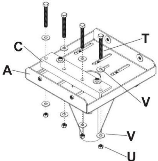
2
Thread four hex nuts (Y) onto four bolts (T). Thread four bolts (T) into side of ceiling plate (A), but do not tighten.
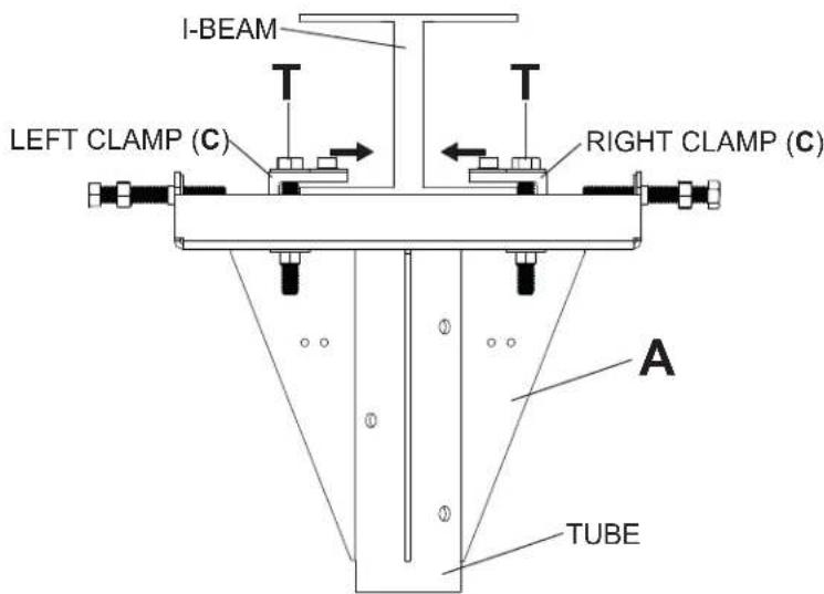
3
Lift ceiling plate (A) up to I-beam and slide ceiling clamps (C) as close to the center of the I-beam as possible. NOTE: Tube of ceiling plate should be centered below I-beam.
Alternate between tightening bolts (T) of right clamp and left clamp until bolts evenly apply force to each clamp.
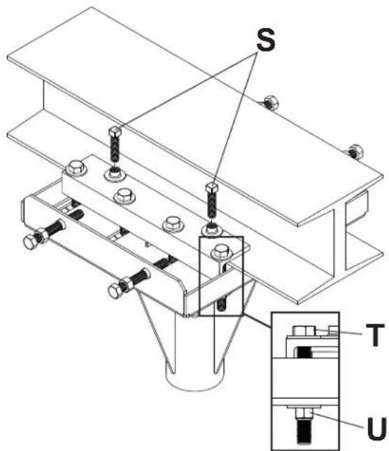
3-1
Tighten square head bolts (S) through ceiling clamp and onto l-beam.
Check bolts (T) and locknuts (U) from previous step to ensure they are still secure.
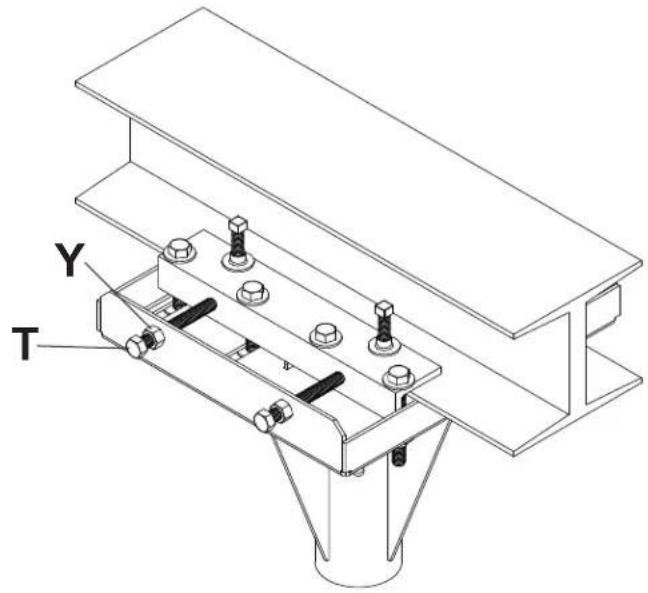
Safety Cable Installation

Tighten bolts (T) on sides of ceiling plate assembly just until they touch the ceiling clamp.
Tighten hex nuts (Y) until they touch the sides of ceiling plate assembly.

Wrap the 5' wire rope (W) tightly around the beam once as shown. Use two cable clips (X) to connect the ends together as shown below.
Once cable clips have been attached, the excess cable ends can be removed.
6
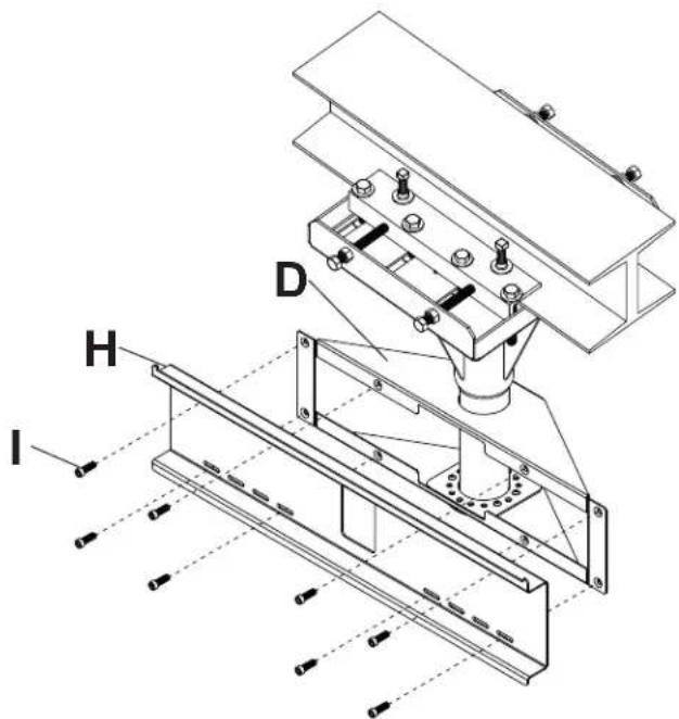
Place adapter box (D) onto support column (B) as shown.
7
Insert support column (B) into ceiling assembly (A). Align holes of support column with holes of ceiling assembly and secure using three 7/16" x 4" bolts (F) and three 7/16" nuts (G) as shown.
8
Adjust swivel to desired position as shown. Secure adapter box to support column with four 1" socket screws (E) using a 3/16" allen wrench as shown.
9
Attach adapter plate (H) to adapter box (D) with eight 3/4" screws (I) using a 3/16" allen wrench as shown.
Installing Tilt Brackets
WARNING
- Tighten screws so adapter brackets are firmly attached. Do not tighten with excessive force. Overtightening can cause stress damage to screws, greatly reducing their holding power and possibly causing screw heads to become detached. Tighten to 40 in. • Ib (4.5 N.M.) maximum torque.
- If screws don't get three complete turns in the screen inserts or if screws bottom out and bracket is still not tightly secured, damage may occur to screen or product may fail.

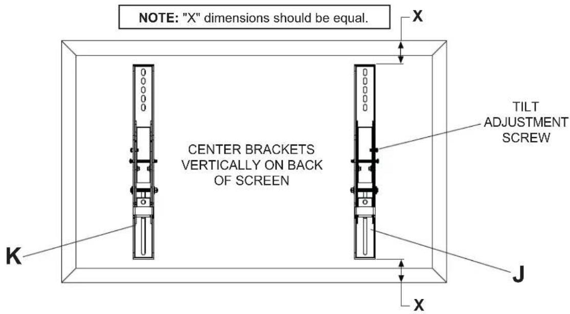
To prevent scratching the screen, set a cloth on a flat, level surface that will support the weight of the screen. Place screen face side down. If screen has knobs on the back, remove them to allow the adapter brackets to be attached. Place adapter brackets (J,K) on back of screen, align to holes, and center on back of screen as shown below. Attach the adapter brackets to the back of the screen using the appropriate combination of screws and washers and as shown in step 10-1.
NOTE: Top and bottom mounting holes on screen must be used for attaching brackets.
NOTE: Be sure to attach tilt brackets with tilt adjustment screw facing outward as shown below.
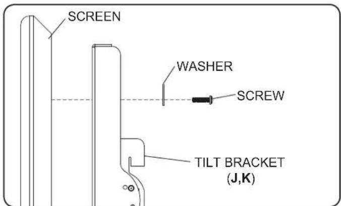
Verify that all holes are properly aligned, and then tighten screws using allen wrench (L).

Begin with the shortest length screw, hand thread through washer and tilt bracket into screen as shown. Screw must make at least three full turns into the mounting hole and fi t snug into place. Do not over tighten. If screw cannot make three full turns into the screen, select a longer length screw from the baffled fastener pack. Repeat for remaining mounting holes, level brackets and tighten screws.
Mounting and Removing Flat Panel Screen
WARNING
• Always use an assistant or mechanical lifting equipment to safely lift and position the fl at panel screen.
- Do not tighten screws with excessive force. Overtightening can cause damage to mount. Tighten screws to 40 in. • lb (4.5 N.M.) maximum torque.
- Be careful not to pinch fingers when pushing screen from the bottom.

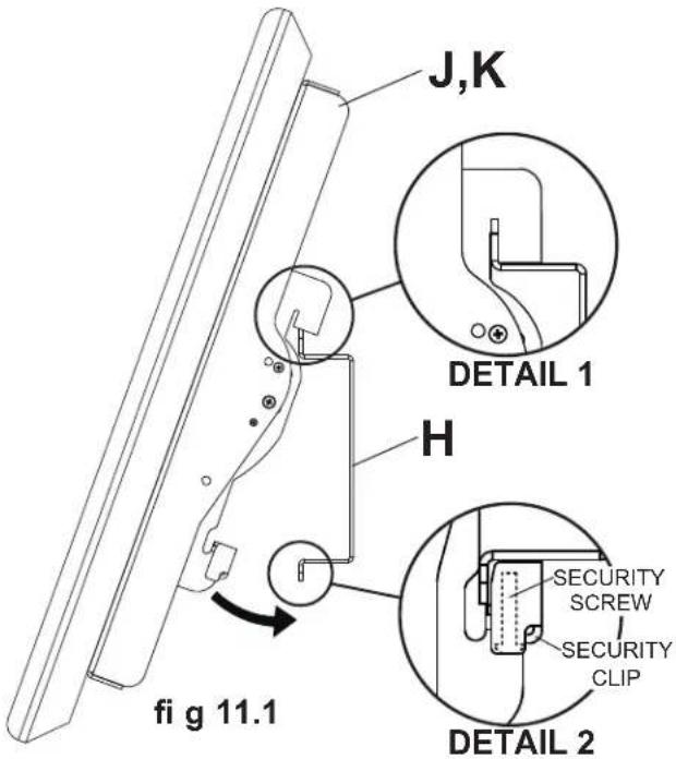
Mounting Screen: Hook tilt brackets (J,K) onto adapter plate (H) and swing screen in as shown in fi g. 11.1. NOTE: If the security clip does not clear the bottom of the adapter plate, loosen the security screw with allen wrench (L). Tilt bracket hooks must fully engage adapter plate as shown in detail 1. Tighten security screw using allen wrench (L) until security clip sits firmly against bottom of adapter plate.
NOTE: Be sure security clip is secured to bottom of adapter plate as shown in detail 2.
Removing Screen: Loosen security screw from security clip until the screen is able to swing freely, and lift screen off of mount.
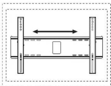
Screen Adjustment: Screen can be adjusted horizontally by loosening security screw three full turns using allen wrench (L). Adjust screen as shown in figure 11.2. Tighten security screw.
natural_image
Pure schematic diagram of a mechanical or electrical component with no text, numbers, or symbolsfig 11.2
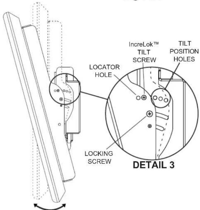
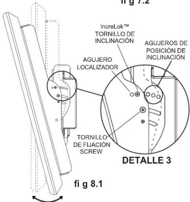
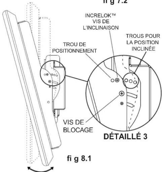
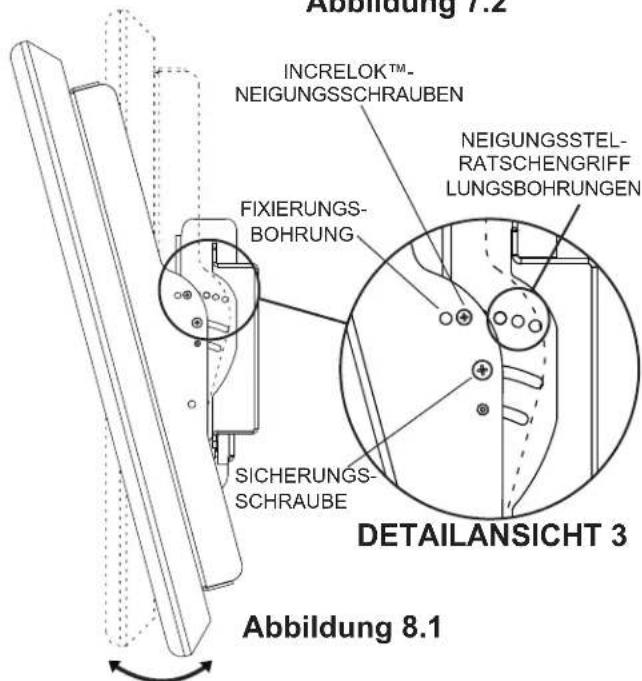
Adjusting the Tilt Angle of the Flat Panel Screen

NOTE: Choosing and setting tilt position may be easier before placing screen onto wall mount.
INCRELOK™: The screen can be locked into a pre-set tilt position of -5°, 0°, 5°, 10° or 15°. Use locator hole to find tilt position hole and tilt screen to align holes. Tighten IncreLok™ tilt screws on both tilt brackets as shown in detail 3.
Tighten locking screw to lock down tilt position.
natural_image
Technical line drawing of a mechanical assembly with two views: top shows a structural frame and column, bottom shows a metal frame with bolts and supports (no text or symbols)

natural_image
Technical line drawing of a mechanical component with labeled points A and C (no text or symbols beyond labels)
natural_image
Technical line drawing of a mechanical bracket with mounting holes and a central circular feature (no text or symbols)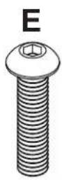

natural_image
Two identical electrical devices labeled J and K, shown side by side with wires and connectors (no text or symbols on the devices themselves)
natural_image
Technical line drawing of a structural beam with supports and a labeled section H (no text or symbols beyond label)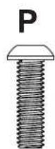
natural_image
Illustration of a hexagonal bolt with threaded shaft (no text or symbols)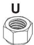

L
ADVERTENCIA

natural_image
Diagram of a mechanical or electrical component with two vertical bars and a central rectangle, no text or symbols present.fi g 7.2
natural_image
Technical line drawing of a mechanical assembly with two views: top shows a structural frame and column, bottom shows a metal frame with mounting brackets (no text or symbols)

Installation de support adaptatuers ....23
natural_image
Technical line drawing of a mechanical bracket with labeled points A and C (no text or symbols beyond labels)
natural_image
Technical line drawing of a mechanical bracket with mounting holes and a central hole, labeled D and J (no text or symbols beyond labels)
natural_image
Two identical 3D illustrations of a vertical device with labeled ports (J and K), showing internal components and wiring (no text or symbols beyond labels)
natural_image
Technical line drawing of a structural beam with supports and a labeled section H (no text or symbols beyond label)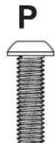


L
▲ AVERTISSEMENT

natural_image
Diagram of a mechanical or electrical component with two vertical bars and a central rectangular block, no text or symbols present.fi g 7.2
natural_image
Technical line drawing of a mechanical assembly with two views: top shows a structural frame and column, bottom shows a metal frame with bolts and supports (no text or symbols)

natural_image
Technical line drawing of a mechanical bracket with labeled points A and C (no text or symbols beyond labels)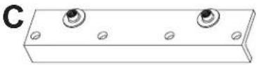
natural_image
Technical line drawing of a mechanical bracket with mounting holes and a central circular feature (no text or symbols)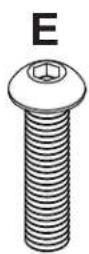

natural_image
Two identical 3D diagrams of a vertical device with labeled ports (J and K), showing internal components and wiring (no text or symbols beyond labels)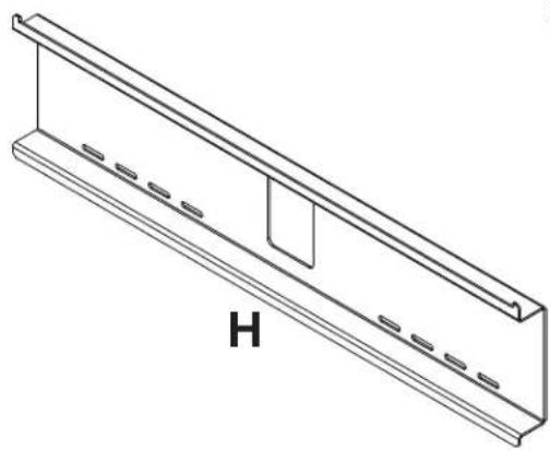
natural_image
Technical line drawing of a structural beam with supports and a labeled section H (no text or symbols beyond label)


L
⚠️ ACHTUNG


natural_image
Technical line drawing of a mechanical assembly with labeled components Y and T (no text or symbols beyond labels)
⚠️ ACHTUNG
natural_image
Diagram of a mechanical or electrical component with two vertical bars and a central rectangle, no text or symbols present.Abbildung 7.2
Peerless Industries, Inc. establishes a warranty period of one year for products manufactured or supplied by Peerless. This period commences from the date of sale of the product to the original consumer, but will in no case last for more than six years after the date of the product's manufacture. During the warranty period such products will be free from defects in material and workmanship, provided they are installed and used in compliance with the instructions established by Peerless Industries, Inc. Subject to applicable legal requirements, during the warranty period Peerless will repair or replace, or refund the purchase price of, any such product which fails to conform with this warranty.
Any other warranties prescribed by the law which may apply with respect to such products also are limited in duration to the warranty period specified in this Limited Five-Year Warranty.
This warranty does not cover damage caused by (a) service or repairs by the customer or a person who is not authorized for such service or repairs by Peerless Industries, Inc., (b) the failure to utilize proper packing when returning the product, (c) incorrect installation or the failure to follow Peerless' instructions or warnings when installing, using or storing the product, or (d) misuse or accident, in transit or otherwise, including in cases of third party actions and force majeure.
In no event shall Peerless be liable for incidental or consequential damages or damages arising from the theft of any product, whether or not secured by a security device which may be included with the product.
This Limited Five-Year Warranty is in lieu of all other warranties, expressed or implied, and is the sole remedy with respect to product defects. No retailer, dealer, distributor, installer or other person is authorized to modify or extend this warranty or impose any obligation on Peerless in connection with the sale of any product manufactured or supplied by Peerless.
This warranty gives specific legal rights, and you may also have other rights provided by the national legislation of the country in which you purchased such product.

www.peerlessmounts.com
© 2008 Peerless Industries, Inc.
LIMITED ONE-YEAR WARRANTY
Limited one-year warranty on corrosion.

www.peerlessmounts.com
© 2008 Peerless Industries, Inc.
GARANTIE DE CINQ ANS
www.peerlessmounts.com
© 2008 Peerless Industries, Inc.
GARANTIE DE UNO AÑO
www.peerlessmounts.com
© 2008 Peerless Industries, Inc.
GARANTÍA LIMITADA DE CINCO AÑOS
www.peerlessmounts.com
© 2008 Peerless Industries, Inc.
GARANTÍA LIMITADA DE UN ANNÉE
www.peerlessmounts.com
© 2008 Peerless Industries, Inc.
BESCHRÄNKTEN FÜNFJÄHRIGEN GARANTIE
www.peerlessmounts.com
© 2008 Peerless Industries, Inc.
BESCHRÄNKTEN EINJÄHRIGEN GARANTIE
www.peerlessmounts.com
© 2008 Peerless Industries, Inc.


- Installation and Assembly:
- Wind Rated I-beam Tilt Mount for 32" - 65" Outdoor Flat Panel Displays
- WARNING
- Tools Needed for Assembly
- Table of Contents
- Installation to I-beam
- Safety Cable Installation
- Installing Tilt Brackets
- Mounting and Removing Flat Panel Screen
- Adjusting the Tilt Angle of the Flat Panel Screen
- ADVERTENCIA
- ▲ AVERTISSEMENT
- ⚠️ ACHTUNG
- LIMITED ONE-YEAR WARRANTY
- GARANTIE DE CINQ ANS
- GARANTIE DE UNO AÑO
- GARANTÍA LIMITADA DE CINCO AÑOS
- GARANTÍA LIMITADA DE UN ANNÉE
- BESCHRÄNKTEN FÜNFJÄHRIGEN GARANTIE
- BESCHRÄNKTEN EINJÄHRIGEN GARANTIE
Brand : Peerless-AV
Model : ECMU02IS
Category : Flat screen mount