
SUF661 - Flat screen mount Peerless-AV - Free user manual and instructions
Find the device manual for free SUF661 Peerless-AV in PDF.


| Product Type | Wall Mount for Flat Screen |
| Brand | Peerless-AV |
| Model | SUF661 |
| Screen Compatibility | Screens from 37 to 70 inches |
| VESA Standard | Up to 600 x 400 mm |
| Maximum Supported Weight | 68 kg (150 lb) |
| Tilt | 0° (fixed) |
| Orientation | Landscape only |
| Material | Robust steel with black finish |
| Mount Dimensions | Width: 75 cm, Height: 45 cm, Depth: 5 cm |
| Mount Weight | 4.5 kg |
| Wall Fixation | Mounting on load-bearing wall (concrete or wood) |
| Built-in Bubble Level | Yes |
| Locking System | Security padlock (optional) |
| Cable Management | Integrated cable routing |
| Maintenance and Cleaning | Clean with a soft, dry cloth |
| Safety | Use only on load-bearing wall; respect load capacity |
| Spare Parts and Repairability | Parts available from manufacturer; technical support by phone |
| Warranty | 5 years |
| Package Contents | Mount, screws, installation manual, template |
Frequently Asked Questions - SUF661 Peerless-AV
User questions about SUF661 Peerless-AV
0 question about this device. Answer the ones you know or ask your own.
Ask a new question about this device
Download the instructions for your Flat screen mount in PDF format for free! Find your manual SUF661 - Peerless-AV and take your electronic device back in hand. On this page are published all the documents necessary for the use of your device. SUF661 by Peerless-AV.
USER MANUAL SUF661 Peerless-AV
Installation and Assembly:
Peerless Ultra-Thin Flat Mount for 37" - 65" (94 - 165 cm)\* Flat Panel Displays
Model: SUF661

natural_image
Technical line drawing of a mechanical component with spring-like grooves and a handle (no text or symbols)\*Display Compatibility Requirements
- The depth of this mount (0.19") may not provide sufficient space for proper ventilation on some displays. Please refer to the manufacturer's requirements for mounting your display before installation.
- The display must have a fl at mounting surface, or the mounting holes need to be on the furthest back surface of the display.
- Input/Output connection must be properly oriented to accommodate mounting 0.19" from the wall.

Max UL Load Capacity: 150 lb (68kg)
WARNING
- Do not begin to install your Peerless product until you have read and understood the instructions and warnings contained in this Installation Sheet. If you have any questions regarding any of the instructions or warnings, for US customers please call Peerless customer care at 1-800-865-2112, for all international customers, please contact your local distributor.
- This mount is designed to attach the display 0.19" from the wall. Please refer to manufacturer's installation guide recommendations for required distance from wall to avoid risk of injury or property damage.
- This product should only be installed by someone of good mechanical aptitude, has experience with basic building construction, and fully understands these instructions.
- Make sure that the supporting surface will safely support the combined load of the equipment and all attached hardware and components.
- Never exceed the Maximum UL Load Capacity. See page one.
- If mounting to wood wall studs, make sure that mounting screws are anchored into the center of the studs. Use of an "edge to edge" stud fi nder is highly recommended.
• Always use an assistant or mechanical lifting equipment to safely lift and position equipment. - Tighten screws firmly, but do not overtighten. Overtightening can damage the items, greatly reducing their holding power.
- This product is intended for indoor use only. Use of this product outdoors could lead to product failure and personal injury.
- This product was designed to be installed on the following wall construction only;
WALL CONSTRUCTION HARDWARE REQUIRED
- Wood Stud Included
• Wood Beam Included
• Solid Concrete Included
• Cinder Block Included
• Metal Stud Contact Qualified Professional (not evaluated by UL) - Brick Contact Qualified Professional (not evaluated by UL)
- Other or unsure? Contact Qualified Professional (not evaluated by UL)
Tools Needed for Assembly
- stud fi nder ("edge to edge" stud fi nder is recommended)
- drill
- 5/16" (8mm) bit for concrete and cinder block wall
- 5/32" (4mm) bit for wood stud wall
- level
Table of Contents
Parts List....3
Installation to Wood Stud Wall....4,5
Installation to Solid Concrete/Cinder Block walls 6
Installing Display Screws....7
Mounting Flat Panel Display....8
Before you begin, make sure all parts shown are included with your product.
Parts may appear slightly different than illustrated.

Installation to Double Wood Stud Wall
WARNING
• Installer must verify that the supporting surface will safely support the combined load of the equipment and all attached hardware and components.
- Tighten wood screws so that wall plate is firmly attached, but do not overtighten. Overtightening can damage the screws, greatly reducing their holding power.
- Never tighten in excess of 80 in. • Ib (9 N.M.).
- Make sure that mounting screws are anchored into the center of the stud. The use of an "edge to edge" stud finder is highly recommended.
- Hardware provided is for attachment of mount through standard thickness drywall or plaster into wood studs. Installers are responsible to provide hardware for other types of mounting situations (not evaluated by UL).

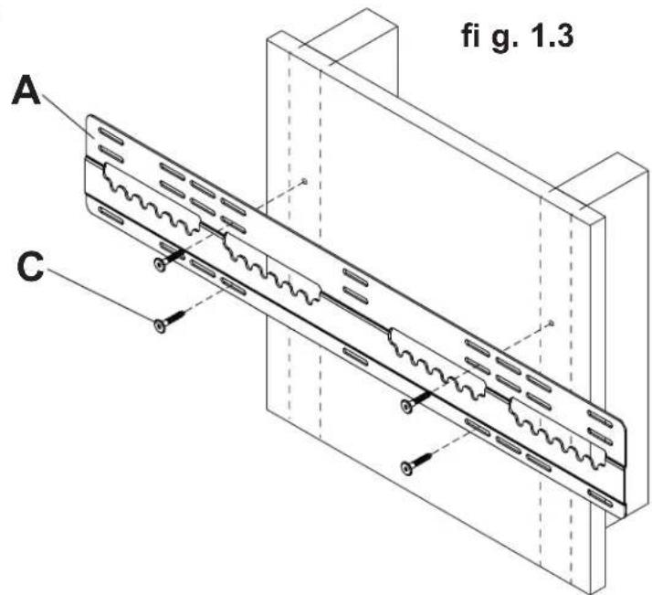
Wall plate (A) can be mounted to two studs that are 16", 20", or 24" apart. Use a stud finder to locate the edges of the studs. Use of an edge-to-edge stud fi nder is highly recommended. Based on their edges, draw a vertical line down each stud's center. Place wall plate on wall as a template. The top mounting slots should be located X" above the desired display center as shown in fi gure 1.1 and 1.2. Level plate, and mark the center of the four mounting holes. Make sure that the mounting holes are on the stud centerlines. Drill four 5/32" (4mm) dia. holes 2" (51mm) deep. Make sure that the wall plate is level and secure it using four wood screws (C) as shown in fi gure 1.3.

NOTE: When mounting wall plate (A) to two studs, do not use center mounting holes or outer mounting holes.
Installation to Triple Wood Stud Wall
WARNING
• Installer must verify that the supporting surface will safely support the combined load of the equipment and all attached hardware and components.
- Tighten wood screws so that wall plate is firmly attached, but do not overtighten. Overtightening can damage the screws, greatly reducing their holding power.
- Never tighten in excess of 80 in. • Ib (9 N.M.).
- Make sure that mounting screws are anchored into the center of the stud. The use of an "edge to edge" stud finder is highly recommended.
- Hardware provided is for attachment of mount through standard thickness drywall or plaster into wood studs. Installers are responsible to provide hardware for other types of mounting situations (not evaluated by UL).

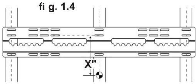
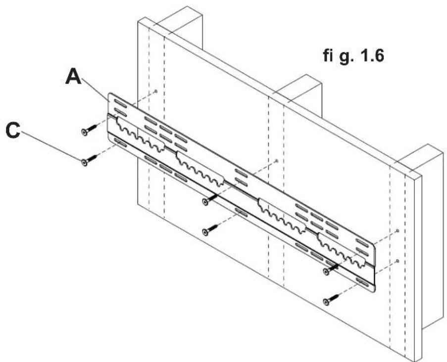
Wall plate (A) can be mounted to three studs that are 16" apart. Use a stud finder to locate the edges of the studs. Use of an edge-to-edge stud fi nder is highly recommended. Based on their edges, draw a vertical line down each stud's center. Place wall plate on wall as a template. The top mounting slots should be located X" above the desired display center as shown in fi gure 1.4 and 1.5. Level plate, and mark the center of the six mounting holes. Make sure that the mounting holes are on the stud centerlines. Drill six 5/32" (4mm) dia. holes 2" (51mm) deep. Make sure that the wall plate is level and secure it using six wood screws (C) as shown in figure 1.6.

Installation to Solid Concrete or Cinder Block
WARNING
- When installing Peerless wall mounts on cinder block, verify that you have a minimum of 1-3/8" of actual concrete thickness in the hole to be used for the concrete anchors. Do not drill into mortar joints! Be sure to mount in a solid part of the block, generally 1" minimum from the side of the block. Cinder block must meet ASTM C-90 specifications. It is suggested that a standard electric drill on slow setting is used to drill the hole instead of a hammer drill to avoid breaking out the back of the hole when entering a void or cavity.
- Two wood screws (C) must be installed into wall plate (A) in each segment as shown in detail 1, or product may fail.
- Concrete must be 2000 psi density minimum. Lighter density concrete may not hold concrete anchor.
- Installer must verify that the supporting surface will safely support the combined load of the equipment and all attached hardware and components.

Make sure that wall plate (A) is level, use it as a template to mark six mounting holes. The top mounting slots should be located X" above the desired display center as shown in figure 1.4 and 1.5 on page 5. Drill six 5/16" (8mm) dia. holes to a minimum depth of 2.5" (64mm). Insert anchors (D) in holes fl ush with wall as shown (right). Place wall plate over anchors and secure with six wood screws (C). Level, then tighten all fasteners.
WARNING
- Tighten screws so that wall plate is firmly attached, but do not overtighten. Overtightening can damage screws, greatly reducing their holding power.
- Never tighten in excess of 80 in. • Ib (9 N.M.).
- Always attach concrete anchors directly to load-bearing concrete.
- Never attach concrete anchors to concrete covered with plaster, drywall, or other fi nishing material. If mounting to concrete surfaces covered with a fi nishing surface is unavoidable (not evaluated by UL), the fi nishing surface must be counterbored as shown below. Be sure concrete anchors do not pull away from concrete when tightening screws. If plaster/drywall is thicker than 5/8", custom fasteners must be supplied by installer (not evaluated by UL).
CUTAWAY VIEW
INCORRECT CORRECT

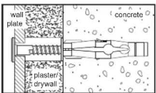

Drill holes and insert anchors (D).
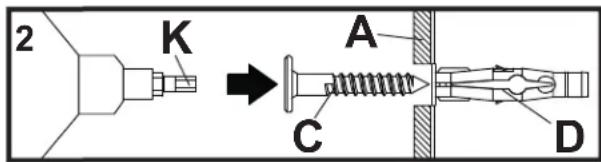
Place plate (A) over anchors (D) and secure with screws (C).

Tighten all fasteners.

DETAIL 1

natural_image
Pure schematic diagram of a mechanical or electrical component with no text, numbers, or symbolsSEGMENT 1 SEGMENT 2 SEGMENT 3
Installing Display Screws
WARNING
- Tighten screws so they are firmly attached. Do not tighten with excessive force. Overtightening can cause stress damage to screws, greatly reducing their holding power and possibly causing screw heads to become detached. Tighten to 40 in. • Ib (4.5 N.M.) maximum torque.
- If screws don't get three complete turns in the display inserts or if screws bottom out and bracket is still not tightly secured, damage may occur to display or product may fail.

To prevent scratching the display, set a cloth on a flat, level surface that will support the weight of the display. Place display face side down. If display has knobs on the back, remove them to allow the adapter brackets to be attached.
NOTE: Top and bottom holes of display must always be used.
For Flat Back Display

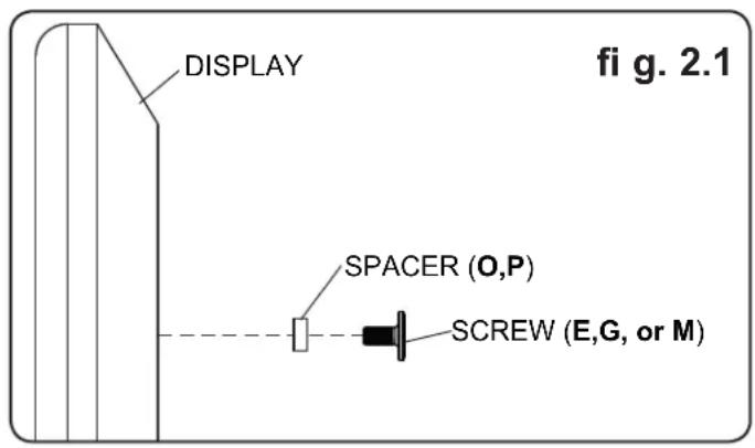
Begin with the shortest length screw (E,G, or M) and hand thread through 1/8" spacer (O,P) into display as shown in figure 2.1. Screw must make at least three full turns into the mounting hole and fit snug into place. Do not over tighten. If screw cannot make three full turns into the display, select a longer length screw (F,H, or N) from the baffled fastener pack. Repeat for remaining mounting holes and tighten screws.
Mounting Flat Panel Display
WARNING
• Always use an assistant or mechanical lifting equipment to safely lift and position the flat panel displays.

Apply cloth bumpers (Q) to bottom mounting screws as shown in figure 3.1.
Hook top mounting screws into wallplate grooves.

Secure display by inserting lock arm (B) into wall plate (A) as shown in figure 3.2.
Lock arm must reside over top of display mounting screws as shown in detail 2.


OPTIONAL: Securing Locking Arm
CAUTION
- Be careful not to pinch fingers when adjusting locking arm (B).

WOOD STUD: Adjust locking arm (B) until it aligns to wood stud and secure using one #10 x 1-1/2" security wood screw (R). If locking arm is diffi cult to adjust, spin arm to loosen joint.


CONCRETE/CINDER BLOCK: Adjust locking arm (B) to desired position, mark center of mounting hole, and drill one 1/4" (6mm) dia. hole to a minimum depth of 2". Insert alligator anchor (S) into hole and secure locking arm (B) with one #10 x 1-1/2" security wood screw (R). If locking arm is diffi cult to adjust, spin arm to loosen joint.

natural_image
Line drawing of a mechanical component with spring-like grooves and a handle, no text or symbols presentnatural_image
Technical line drawing of a bent pipe or rod with labeled component 'L' and part 'M' (no text or symbols beyond labels)
N

O

P

Q

R

S

ADVERTENCIA
natural_image
Pure mechanical diagram showing three sequential stages of a gear or cam mechanism with no text or symbolsnatural_image
Technical line drawing of a mechanical component with spring-like grooves and a handle (no text or symbols)natural_image
Pure mechanical diagram showing two parallel plates connected by a spring, with no text or symbols present.SEGMENT 1 SEGMENT 2 SEGMENT 3
▲ AVERTISSEMENT
LIMITED FIVE-YEAR WARRANTY
Peerless Industries, Inc. ("Peerless") warrants to original end-users of Peerless® products will be free from defects in material and workmanship, under normal use, for a period of five years from the date of purchase by the original end-user (but in no case longer than six years after the date of the product's manufacture). At its option, Peerless will repair or replace, or refund the purchase price of, any product which fails to conform with this warranty.
In no event shall the duration of any implied warranty of merchantability or fitness for a particular purpose be longer than the period of the applicable express warranty set forth above. Some states do not allow limitations on how long an implied warranty lasts, so the above limitation may not apply to you.
This warranty does not cover damage caused by (a) service or repairs by the customer or a person who is not authorized for such service or repairs by Peerless, (b) the failure to utilize proper packing when returning the product, (c) incorrect installation or the failure to follow Peerless' instructions or warnings when installing, using or storing the product, or (d) misuse or accident, in transit or otherwise, including in cases of third party actions and force majeure.
In no event shall Peerless be liable for incidental or consequential damages or damages arising from the theft of any product, whether or not secured by a security device which may be included with the Peerless® product. Some states do not allow the exclusion or limitation of incidental or consequential damages, so the above limitation or exclusion may not apply to you.
This warranty is in lieu of all other warranties, expressed or implied, and is the sole remedy with respect to product defects. No dealer, distributor, installer or other person is authorized to modify or extend this Limited Warranty or impose any obligation on Peerless in connection with the sale of any Peerless® product.
This warranty gives specific legal rights, and you may also have other rights which vary from state to state.
peerless-AV
www.peerlessmounts.com
© 2011 Peerless Industries, Inc.
Español
GARANTÍA LIMITADA DE CINCO AÑOS
www.peerlessmounts.com
© 2011 Peerless Industries, Inc.
GARANTIE DE CINQ ANS
www.peerlessmounts.com
© 2011 Peerless Industries, Inc.

- Installation and Assembly:
- Peerless Ultra-Thin Flat Mount for 37" - 65" (94 - 165 cm)\* Flat Panel Displays
- \*Display Compatibility Requirements
- WARNING
- WALL CONSTRUCTION HARDWARE REQUIRED
- Tools Needed for Assembly
- Table of Contents
- Installation to Double Wood Stud Wall
- Installation to Triple Wood Stud Wall
- Installation to Solid Concrete or Cinder Block
- Installing Display Screws
- For Flat Back Display
- Mounting Flat Panel Display
- OPTIONAL: Securing Locking Arm
- CAUTION
- ADVERTENCIA
- ▲ AVERTISSEMENT
- LIMITED FIVE-YEAR WARRANTY
- GARANTÍA LIMITADA DE CINCO AÑOS
- GARANTIE DE CINQ ANS
Brand : Peerless-AV
Model : SUF661
Category : Flat screen mount