
SCAS30 - Loudspeaker SONY - Free user manual and instructions
Find the device manual for free SCAS30 SONY in PDF.
| Product Type | Active speaker (amplified loudspeaker) for security systems |
| Brand | Sony |
| Model | SCA-S30 |
| Dimensions (W x H x D) | 167 x 273 x 255 mm (including frame) |
| Diameter | 150 mm |
| Weight | Approx. 2.4 kg (including frame) |
| Power Supply | 24 V AC, max. power consumption 8 W (1/8 W undistorted output), max. current 2.8 A |
| Frequency Response | 100 Hz to 15,000 Hz (5 W output) |
| Maximum Output Level | 35 W or more (24 V AC input, 1 kHz) |
| Input Impedance | 10 kΩ or more |
| Signal-to-Noise Ratio | 80 dB or more (IEC179 A-weighted, 1 kHz, 30 W) |
| Input Connectors | 1 x AUDIO IN (stereo mini jack 3-pole/2-pole), 1 x 24 V AC power input, 1 x ground terminal |
| Protection Rating | IP66 (dust-tight and splash-proof) |
| Operating Temperature | -20 to +50 °C (-4 to +122 °F) |
| Operating Humidity | 20% to 80% (non-condensing) |
| Storage Temperature | -20 to +60 °C (-4 to +140 °F) |
| Storage Humidity | 20% to 95% (non-condensing) |
| Key Features | Built-in amplifier, compact and lightweight design, wall or pole mount, angle adjustment, safety cable included |
| Maintenance and Cleaning | Wipe with a dry cloth; for stubborn stains, use a mild neutral detergent then dry; do not use alcohol, solvents, or volatile substances |
| Safety | Safety wire cable provided; installation by qualified technician; grounding mandatory; periodic inspection recommended once a year |
| Spare Parts and Repairability | Contact an authorized Sony dealer for repairs; the unit contains no user-serviceable parts |
| Supplied Accessories | Safety wire cable, M4x16 mounting screws, instruction manual, warranty booklet |
| Warranty | Sony limited warranty; refer to enclosed documents or Sony website for terms |
Frequently Asked Questions - SCAS30 SONY
User questions about SCAS30 SONY
0 question about this device. Answer the ones you know or ask your own.
Ask a new question about this device
Download the instructions for your Loudspeaker in PDF format for free! Find your manual SCAS30 - SONY and take your electronic device back in hand. On this page are published all the documents necessary for the use of your device. SCAS30 by SONY.
USER MANUAL SCAS30 SONY
Operating Instructions ____ GB
natural_image
Technical line drawing of a mechanical component with flanged ends and mounting bracket (no text or symbols)①パワーインジケーター(POWER)
通電しているときに緑色に点灯します。
natural_image
Technical diagram showing a mechanical clamp securing a cylindrical component mounted on a vertical panel (no text or symbols present)メモ
natural_image
Technical line drawing of a mechanical assembly with bolts and a cylindrical component (no text or symbols)natural_image
Technical line drawing of a mechanical component with a central shaft and mounting bracket (no text or symbols)natural_image
Technical line drawing of a mechanical assembly with a cylindrical component and mounting bracket (no text or symbols)natural_image
Technical line drawing of a mechanical assembly with no visible text or symbols
natural_image
Line drawing of a mechanical arm joint with a cable and spring (no text or symbols)natural_image
Technical diagram showing a pipe fitting attached to a mechanical bracket with cable (no text or symbols)壁に設置する場合

natural_image
Line drawing of a hand holding a device with cable, next to a vertical wall (no text or symbols)メモ
natural_image
Technical line drawing of a mechanical assembly with mounting flange and connecting rod (no text or symbols)natural_image
Technical line drawing of a mechanical clamp or bracket assembly (no text or symbols)natural_image
Technical line drawing of a mechanical device with mounting holes and a flat surface (no text or symbols)natural_image
Technical line drawing of a mechanical assembly with no visible text or symbols
natural_image
Line drawing of a mechanical lever assembly with a handle and pivot (no text or symbols)natural_image
Technical line drawing of a mechanical assembly with a vertical rod and attached bracket (no text or symbols)電源の接続
本機は、次の方法で電源を接続できます。
- AC 24 V
AC 24 V 電源への接続
Before operating the unit, please read this manual thoroughly and retain it for future reference.
WARNING
To avoid electrical shock, do not open the cabinet. Refer servicing to qualified personnel only.
Power Supply
The SCA-S30 operates on AC 24 V power. The SCA-S30 automatically detects the power. In the USA, use a Class 2 power supply which is UL Listed. In Canada, use a CSA-certified Class 2 power supply.
Important Safety Instructions
- Read these instructions.
- Keep these instructions.
- Heed all warnings.
- Follow all instructions.
- Do not use this apparatus near water.
- Clean only with dry cloth.
- Do not block any ventilation openings. Install in accordance with the manufacturer's instructions.
- Do not install near any heat sources such as radiators, heat registers, stoves, or other apparatus (including amplifiers) that produce heat.
- Do not defeat the safety purpose of the polarized or grounding-type plug. A polarized plug has two blades with one wider than the other. A grounding-type plug has two blades and a third grounding prong. The wide blade or the third prong are provided for your safety. If the provided plug does not fit into your outlet, consult an electrician for replacement of the obsolete outlet.
- Protect the power cord from being walked on or pinched particularly at plugs, convenience receptacles, and the point where they exit from the apparatus.
- Only use attachments/accessories specified by the manufacturer.
- Use only with the cart, stand, tripod, bracket, or table specified by the manufacturer, or sold with the apparatus. When a cart is used, use caution when moving the cart/apparatus combination to avoid injury from tip-over.

- Unplug this apparatus during lightning storms or when unused for long periods of time.
- Refer all servicing to qualified service personnel. Servicing is required when the apparatus has been damaged in any way, such as power-supply cord or plug is damaged, liquid has been spilled or objects have fallen into the apparatus, the apparatus has been exposed to rain or moisture, does not operate normally, or has been dropped.
For the customers in the U.S.A.
This equipment has been tested and found to comply with the limits for a Class A digital device, pursuant to Part 15 of the FCC Rules. These limits are designed to provide reasonable protection against harmful interference when the equipment is operated in a commercial environment. This equipment generates, uses, and can radiate radio frequency energy and, if not installed and used in accordance with the instruction manual, may cause harmful interference to radio communications. Operation of this equipment in a residential area is likely to cause harmful interference in which case the user will be required to correct the interference at his own expense.
You are cautioned that any changes or modifications not expressly approved in this manual could void your authority to operate this equipment.
All interface cables used to connect peripherals must be shielded in order to comply with the limits for a digital device pursuant to Subpart B of Part 15 of FCC Rules.
This device complies with Part 15 of the FCC Rules. Operation is subject to the following two conditions: (1) this device may not cause harmful interference, and (2) this device must accept any interference received, including interference that may cause undesired operation.
For the customers in Canada
CAN ICES-3 (A)/NMB-3(A)
For the customers in Europe
This product is intended for use in the following Electromagnetic Environments: E1 (residential), E2 (commercial and light industrial), E3 (urban outdoors), E4 (controlled EMC environment, ex. TV studio).
For the customers in Europe
This product has been manufactured by or on behalf of Sony Corporation, 1-7-1 Konan Minato-ku Tokyo, 108-0075 Japan. Inquiries related to product compliance based on European Union legislation shall be addressed to the authorized representative, Sony Belgium, bijkantoor van Sony Europe Limited, Da Vincilaan 7-D1, 1935 Zaventem, Belgium. For any service or guarantee matters, please refer to the addresses provided in the separate service or guarantee documents.
Package Contents ....5
Names and Functions of Parts ......6
Front 6
Rear 7
Bottom 8
Installation 9
Pole or Column Installation .....10
Wall Installation ....15
Connecting the Power Supply .....20
Precautions ......21
Major Specifications ....21
Dimensions ......23
Trademarks
The products or system names appearing in this document are trademarks or registered trademarks of their respective owners.
Further, the ® or ™ symbols are not used in the text.
Features
The SCA-S30 Active Speaker is intended to be used in combination with security cameras, and is designed with high performance and durability in mind. The speaker is also designed with the following features.
24V AC compatible internal amplifier speaker
The SCA-S30 supports 24 V AC power, allowing power supply consolidation with Sony network cameras.
Wide-area dispersion
The built-in high-output amplifier and high-efficiency speaker enable a wide area of sound dispersion.
Compact, lightweight design
The lightweight yet sturdy design allows for easy installation, and endures wind, vibration, and other external stress.
High reliability and durability
- A reliable design that can withstand vibration and a wide range of operating temperatures, and a durable weatherproof exterior allows for installation in a variety of environments.
- Compliance with the IP66 standard.
- Multiple fail-safes employed to prevent falling.
High sound quality
Circuits and speaker unit that support a wide range of frequencies enable high-quality sound output.
Simple installation
- Arm section fits existing mount brackets.
- Easy speaker angle adjustment via loosening and tightening of the adjustment bolts.
Package Contents
Check that the following items are included in the package. If any of the items are missing, contact your local Sony representative.
- Speaker unit (1)

natural_image
Technical line drawing of a cylindrical mechanical component with flange and mounting bracket (no text or symbols)- Safety wire rope (1)
- Safety wire rope mount screw (M4 × 16) (1)
- Operating Instructions (1)
• Warranty book (1)
Notes
• Additional items such as Pole Mount Adapter Brackets (such as the APM3 from Videolarm), metal banding, cable raceways, and couplings (conduit pipes) for securing speaker installations are not supplied. Customers should procure them as necessary.
• This package may contain additional hardware and/or documentation.
- Save the boxes and packing materials for future use, as they can be used when transporting or shipping the unit.
Names and Functions of Parts
Front

1 Front panel
Sound is emitted from here.
2 Cover
Covers the cable connections.
Be sure to secure it to prevent detachment.
3Frame
Used for mounting the speaker onto a wall or pole.
Use the screws supplied with the mount bracket (not supplied) to secure the speaker.
4 Adjustment bolts
Adjusts the angle of the speaker.
Tighten the bolts to lock the angle.
5 Safety wire rope holes
Run the safety wire rope through here.
Always attach the safety wire rope to prevent the unit from falling. (See page 13)
Rear

This is the LINE input connector.
Although 3-pole mini stereo is supported, stereo inputs will be output in monaural.
2 Power input connector (24 V AC)
Connect to a 24 V AC power supply unit.
3 Grounding terminal (m)
Used for grounding the unit. Always ground the unit.
4 Safety wire rope holes
Run the safety wire rope through here.
Always attach the safety wire rope to prevent the unit from falling. (See page 13)
Bottom

1 POWER indicator
Lights green when power is supplied.
② Connection port (for conduit fittings) NPT 3/4
Connect raceways and couplings (conduit fittings) here.
Installation
WARNING
- Contact a qualified technician when installing the unit on a ceiling or high location.
- When installing the unit in a high location, make sure that the location can support the weight of the unit and parts for installation, and make sure the unit is secured. Failure to do so may result in injuries.
- Always attach the supplied safety wire rope to prevent the unit from falling.
- When the unit is installed in a high location, inspect the installation once a year and check for loose fixtures. Increase the frequency of inspection depending on the installation location.
This display conforms to international dust and splash proof standard IEC60529 IP66 and so can be used in a location where a lot of dust particles or splashing water may be produced. The performance indicated by the digits after IP is shown below.
Dust proof
IP6_ Protected against dust.
Definition
Protection against ingress of dust.
Splash proof
IP_6 Protected against splashing water.
Definition
Water splashing against the enclosure from any direction shall have no harmful effect.
Caution
Upside-down installation of the speaker is not recommended, as this may reduce the waterproof properties (IP66 standard) of the speaker.
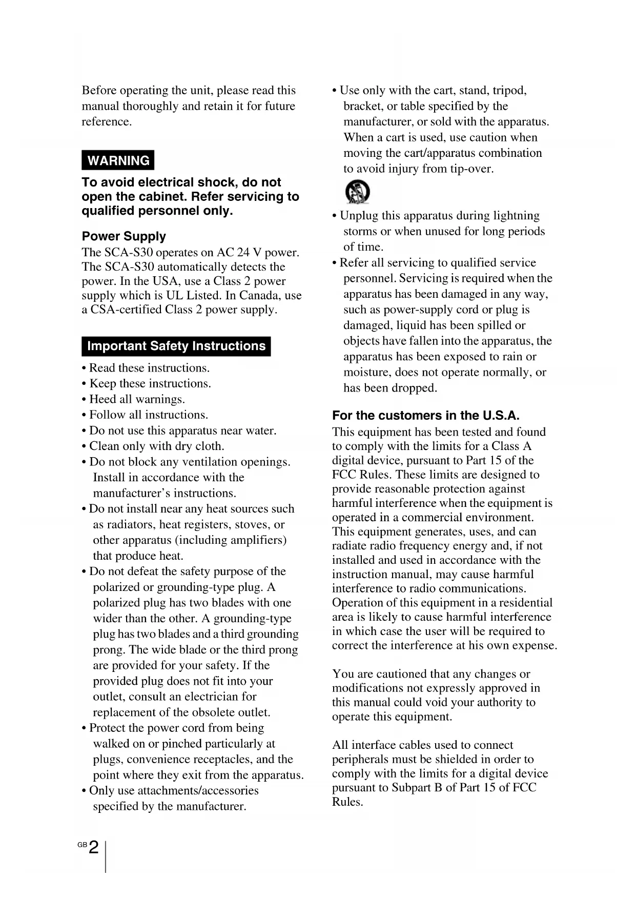
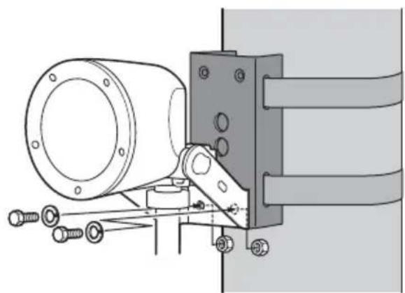
Pole or Column Installation
Use a Pole Mount Adapter Bracket to mount the unit on a pole or column.

natural_image
Technical diagram of a mechanical clamp or bracket assembly with a cylindrical component and connecting rod (no text or symbols)Note
Pole Mount Adapter Brackets, metal banding, cable raceways, couplings, nuts, audio signal cables, and power cables are not supplied. Customers should procure them as necessary.
1 Use metal banding to secure the Pole Mount Adapter Bracket onto the pole or column.

2 Remove the cover at the rear of the speaker.

Notes
• The cover screws are screwed tightly to the speaker and may be difficult to remove.
- The cover is attached to the speaker with a coiled cord.
3 Run the audio signal cable and power cables through the raceway, and attach the coupling.

4 Insert the coupling through the connection port on the speaker, and secure it with the nut supplied with the coupling.

5 Use the nuts and bolts supplied with the Pole Mount Adapter Bracket to secure the speaker to the bracket.
natural_image
Technical line drawing of a mechanical assembly with bolts and a cylindrical component (no text or symbols)6 Connect the audio signal cable and power cables to the speaker.
①Loosen the adjustment bolts on the left and right sides of the speaker as much as possible, and adjust the angle of the speaker as shown.

② Connect the audio signal cable to the AUDIO IN connector, the power cables to the power input connector (24 V AC), and the grounding wire to the grounding terminal () .
- Secure the audio signal cable onto the cable holder to prevent disconnections. - The unit should always be grounded.

7 Attach that cover to the rear of the speaker.
①Fit the cover onto the speaker.

natural_image
Technical line drawing of a mechanical component with a lever and shaft (no text or symbols)②Tighten the cover screws (3) to secure the cover.
Make sure that the cover is fitted onto the speaker snugly, without leaving any gaps.
natural_image
Technical line drawing of a mechanical assembly with a cylindrical component and a bracket (no text or symbols)8 Attach the safety wire rope.
①Run the safety wire rope through a wire rope hole on the speaker as shown. Be sure to use one of the four wire rope holes to secure the speaker.
Example Example

natural_image
Line drawing of a mechanical clamp or bracket assembly (no text or symbols)
natural_image
Line drawing of a mechanical lever assembly with no text or symbols② Use the supplied safety wire rope mount screw (M4 × 16) to secure the rope.

Caution
Use only the supplied screw to secure the safety wire rope. Using a screw other than the one supplied may not provide sufficient support.
9 Adjust the angle of the speaker.
After adjusting the angle, tighten the adjustment bolts on the left and right sides of the speaker to lock the angle.
Tighten the left and right adjustment bolts to lock.

natural_image
Technical diagram showing a pipe fitting connected to a mechanical bracket with cable (no text or symbols)Wall Installation

natural_image
Line drawing of a hand holding a device with a cable, against a plain background (no text or symbols)Note
Cable raceways, couplings, nuts, audio signal cables, and power cables are not supplied. Customers should procure them as necessary.
1 Remove the cover at the rear of the speaker.

Notes
• The cover screws are screwed tightly to the speaker and may be difficult to remove.
- The cover is attached to the speaker with a coiled cord.
2 Run the audio signal cable and power cables through the raceway, and attach the coupling.

3 Insert the coupling through the connection port on the speaker, and secure it with the nut supplied with the coupling.

4 Secure the speaker to the wall.
①Secure two mount bolts to the wall.
When installing the mount bolts, be sure to take into account the distance between the bolt hole centers on the speaker frame and the distance between the speaker cover and the wall.

②Use washers and nuts to secure the speaker.

natural_image
Technical line drawing of a mechanical assembly with mounting flange and connecting rod (no text or symbols)5 Connect the audio signal cable and power cables to the speaker.
①Loosen the adjustment bolts on the left and right sides of the speaker as much as possible, and adjust the angle of the speaker as shown.

② Connect the audio signal cable to the AUDIO IN connector, the power cables to the power input connector (24 V AC), and the grounding wire to the grounding terminal ( ).
- Secure the audio signal cable onto the cable holder to prevent disconnections.
• The unit should always be grounded.

6 Attach that cover to the rear of the speaker.
①Fit the cover onto the speaker.

natural_image
Technical line drawing of a mechanical component with a lever and pivot (no text or symbols)②Tighten the cover screws (3) to secure the cover.
Make sure that the cover is fitted onto the speaker snugly, without leaving any gaps.

natural_image
Technical line drawing of a mechanical device with mounting holes and a handle (no text or symbols)7 Attach the safety wire rope.
①Run the safety wire rope through a wire rope hole on the speaker as shown. Be sure to use one of the four wire rope holes to secure the speaker.
Example Example

natural_image
Technical line drawing of a mechanical assembly with no visible text or symbols
natural_image
Line drawing of a mechanical clamp or bracket assembly (no text or symbols)② Use the supplied safety wire rope mount screw (M4 × 16) to secure the rope.

Caution
Use only the supplied screw to secure the safety wire rope. Using a screw other than the one supplied may not provide sufficient support.
8 Adjust the angle of the speaker.
After adjusting the angle, tighten the adjustment bolts on the left and right sides of the speaker to lock the angle.
Tighten the left and right adjustment bolts to lock.

natural_image
Line drawing of a mechanical device with a vertical line and attached cable, no text or symbols presentConnecting the Power Supply
Supply power to the unit as follows.
- AC 24 V
Connecting to the 24 V AC power supply
Connect to the 24 V AC power supply via the rear power input connector.
- Use a power supply that is isolated from commercially available power. The acceptable voltage range is as follows:
21.6 V to 26.4 V
- Use a UL cable (VW-1 style 1007) for connections.
- Be sure to ground the unit at the grounding terminal () .
- The recommended cables for use in connecting the unit to the power supply are as follows.
| Cable (AWG) #2 | 24 #22 #20 #1 | 18 #16 | |||
| Maximum cable length | 7 m(23 ft.) | 11 m(36 ft.) | 17 m(56 ft.) | 28 m(92 ft.) | 44 m(144 ft.) |
Precautions
Locations for use/storage
To prolong the life of the product, avoid use or storage in the following locations.
- Locations that can become extremely hot or cold. (Operating temperature: -20^ to +50^ ( -4^ to +122^ ))
- Locations exposed for an extended time to direct sunlight, and locations near heating appliances.
- Locations with high levels of humidity or dust
- Locations subject to strong vibrations
- Locations subject to strong magnetic fields
- Locations in the vicinity of radio or TV transmitters creating a strong magnetic field
Protect from shocks and vibrations
Dropping the unit or exposing it to strong shocks may damage the unit.
Maintenance
For cleaning, lightly wipe the cabinet and panels with a dry cloth. To remove stubborn stains, lightly moisten the cloth with a mild, neutral detergent and wipe with a dry cloth afterwards. Do not use cleaning alcohol, solvents, benzine, insecticide, or any other volatile substances, because these may damage the finish and lead to discoloration.
Transport
Use the original packing material or similar packing to protect the unit from shocks.
Major Specifications
Speaker
Category Active speaker
Frequency response
100 Hz to 15,000 Hz
(at 5 W output)
Maximum output level
35 W or more
(at 24 V AC, 1 kHz input)
Input impedance
10 kΩ or more
S/N ratio 80 dB or more
(IEC179 A-weighted,
1 kHz, 30 W)
Input connectors
AUDIO IN connector
Grounding terminal (m) (1)
Operating environment
Temperature -20^ to +50^
(-4^ to +122^)
Humidity 20% to 80%
(no condensation)
Storage environment
Temperature -20 °C to +60 °C
(-4^ to +140^)
Humidity 20% to 95%
(no condensation)
Power requirements and miscellaneous
General
Power supply 24 V AC ± 10%, 50/60 Hz
Maximum current consumption
2.8 A or higher
(at maximum output)
Power consumption
8 W (max.) (24 V AC,
1/8 W of maximum
undistorted output)
Dimensions 150 mm dia. (6 in.)
167 × 273 × 255 ~mm
(6^5/8× 10^3/4× 10^1/_8in.)
(B/H/L) (including frame)
Weight Approx. 2.4 kg (5.28 lb.)
(including frame)
Supplied accessories
Safety wire rope (1)
Safety wire rope mount screw (M4 × 16) (1)
Operating Instructions (1)
Warranty book (1)
Design and specifications are subject to change without notice.
Note
Always verify that the unit is operating properly before use. SONY WILL NOT BE LIABLE FOR DAMAGES OF ANY KIND INCLUDING, BUT NOT LIMITED TO, COMPENSATION OR REIMBURSEMENT ON ACCOUNT OF THE LOSS OF PRESENT OR PROSPECTIVE PROFITS DUE TO FAILURE OF THIS UNIT, EITHER DURING THE WARRANTY PERIOD OR AFTER EXPIRATION OF THE WARRANTY, OR FOR ANY OTHER REASON WHATSOEVER.
Recommendation of Periodic Inspections
In case using this device over an extended period of time, please have it inspected periodically for safe use.
It may appear flawless, but the components may have deteriorated over time, which may cause a malfunction or accident.
For details, please consult the store of purchase or an authorized Sony dealer.
Dimensions
(These dimentions include the frame.)


Unit: mm (inches)
Dispersion large zone
natural_image
Technical line drawing of a mechanical component with flanged ends and a bracket (no text or symbols)1 Indicateur POWER
natural_image
Technical diagram showing a mechanical assembly with a cylindrical component and attached rod (no text or symbols present)Remarque
natural_image
Technical line drawing of a mechanical assembly with bolts and a cylindrical component (no text or symbols)natural_image
Pure mechanical diagram showing a lever and pivot mechanism without any text or symbolsnatural_image
Technical line drawing of a mechanical assembly with a cylindrical component and mounting bracket (no text or symbols)natural_image
Technical line drawing of a mechanical assembly with no visible text or symbols
natural_image
Line drawing of a mechanical clamp or bracket assembly (no text or symbols)natural_image
Technical diagram of a mechanical clamp or bracket assembly with a cylindrical component and connecting rod (no text or symbols)Installation au mur

natural_image
Line drawing of a hand holding a device with a cable, against a plain wall (no text or symbols)Remarque
natural_image
Technical line drawing of a mechanical assembly with no visible text or symbolsnatural_image
Technical line drawing of a mechanical component with a lever and shaft (no text or symbols)natural_image
Technical line drawing of a mechanical device with mounting holes and a flat surface (no text or symbols)natural_image
Technical line drawing of a mechanical assembly with no visible text or symbols
natural_image
Line drawing of a mechanical clamp or bracket assembly (no text or symbols)natural_image
Line drawing of a mechanical device with a lever and attached cable (no text or symbols)Alimentation 24 V CA ± 10%, 50/60 Hz
natural_image
Technical line drawing of a cylindrical mechanical component with flange and mounting bracket (no text or symbols)1 Indicador POWER
natural_image
Technical diagram showing a mechanical clamp securing a cylindrical component mounted on a vertical panel (no text or symbols present)Nota
natural_image
Technical line drawing of a mechanical assembly with bolts and a cylindrical component (no text or symbols)natural_image
Pure mechanical diagram showing a lever and pivot mechanism without any text or symbolsnatural_image
Technical line drawing of a mechanical assembly with a cylindrical component and mounting bracket (no text or symbols)natural_image
Technical line drawing of a mechanical assembly with no visible text or symbols
natural_image
Line drawing of a mechanical component with a curved handle and attached cable (no text or symbols)natural_image
Technical diagram showing a pipe fitting connected to a mechanical bracket with cable (no text or symbols)natural_image
Line drawing of a hand holding a device with a cable, next to a vertical wall (no text or symbols)Nota
natural_image
Technical line drawing of a mechanical assembly with no visible text or symbolsnatural_image
Technical line drawing of a mechanical component with a lever and shaft (no text or symbols)natural_image
Technical line drawing of a mechanical device with mounting holes and a flat surface (no text or symbols)natural_image
Line drawing of a mechanical assembly with no visible text or symbols
natural_image
Line drawing of a mechanical arm joint with a cable and bracket (no text or symbols)natural_image
Line drawing of a mechanical device with a vertical line and cable, no text or symbols present| Cable (AWG) #24 | #22 #20 #18 | #16 | |||
| Longitud máxima de cable | 7 m(23 pies) | 11 m(36 pies) | 17 m(56 pies) | 28 m(92 pies) | 44 m(144 pies) |
Precauciones
natural_image
Technical line drawing of a cylindrical mechanical component with flange and mounting bracket (no text or symbols)1 POWER-LED
natural_image
Technical diagram showing a mechanical clamp securing a wall-mounted component (no text or symbols present)Hinweis
natural_image
Technical line drawing of a mechanical assembly with bolts and a cylindrical component (no text or symbols)natural_image
Technical line drawing of a mechanical component with a lever and pivot (no text or symbols)natural_image
Technical line drawing of a mechanical assembly with a cylindrical component and mounting bracket (no text or symbols)natural_image
Technical line drawing of a mechanical assembly with no visible text or symbols
natural_image
Line drawing of a mechanical arm joint with a cable and spring (no text or symbols)natural_image
Technical diagram showing a pipe fitting connected to a mechanical bracket with cable (no text or symbols)Wandinstallation

natural_image
Line drawing of a hand holding a device with a cable, next to a vertical wall (no text or symbols)Hinweis
natural_image
Technical line drawing of a mechanical assembly with mounting flange and connecting rod (no text or symbols)natural_image
Technical line drawing of a mechanical component with a central shaft and mounting bracket (no text or symbols)natural_image
Technical line drawing of a mechanical device with mounting holes and a flat surface (no text or symbols)natural_image
Technical line drawing of a mechanical assembly with clamping elements (no text or symbols)
natural_image
Line drawing of a mechanical lever assembly with no text or symbolsnatural_image
Line drawing of a mechanical device with a lever and attached cable (no text or symbols)natural_image
Technical line drawing of a cylindrical mechanical component with flange and mounting bracket (no text or symbols)1 Indicatore POWER
natural_image
Technical diagram of a mechanical clamp or bracket assembly with a cylindrical component and connecting rod (no text or symbols)Nota
Note
natural_image
Technical line drawing of a mechanical assembly with bolts and a cylindrical component (no text or symbols)natural_image
Technical line drawing of a mechanical component with a lever and pivot point (no text or symbols)natural_image
Technical line drawing of a mechanical assembly with a cylindrical component and mounting bracket (no text or symbols)natural_image
Technical line drawing of a mechanical assembly with no visible text or symbols
natural_image
Line drawing of a mechanical clamp or bracket assembly (no text or symbols)natural_image
Technical diagram showing a mechanical assembly with a cylindrical component and attached rod (no text or symbols)natural_image
Line drawing of a hand holding a device with a cable, against a plain wall (no text or symbols)Nota
Note
natural_image
Technical line drawing of a mechanical assembly with bolts and a housing (no text or symbols)natural_image
Technical line drawing of a mechanical clamp or bracket assembly (no text or symbols)natural_image
Technical line drawing of a mechanical device with mounting holes and a curved base (no text or symbols)natural_image
Technical line drawing of a mechanical assembly with no visible text or symbols
natural_image
Line drawing of a mechanical clamp or bracket assembly (no text or symbols)natural_image
Technical line drawing of a mechanical assembly with mounting flange and wiring (no text or symbols)natural_image
Line drawing of a hand holding a computer monitor with a cable, no text or symbols presentnatural_image
Technical line drawing of a cylindrical mechanical component with flange and mounting bracket (no text or symbols)①전원 표시등
natural_image
Technical diagram showing a mechanical assembly with a cylindrical component and attached bracket (no text or symbols)참고
natural_image
Technical line drawing of a mechanical assembly with bolts and a cylindrical component (no text or symbols)natural_image
Technical line drawing of a mechanical clamp or bracket assembly (no text or symbols)natural_image
Technical line drawing of a mechanical assembly with a cylindrical component and mounting bracket (no text or symbols)8 안전 와이어 로프를 연결합니다.
natural_image
Technical line drawing of a mechanical assembly with no visible text or symbols예

natural_image
Line drawing of a mechanical lever assembly (no text or symbols)natural_image
Technical diagram showing a pipe fitting connected to a mechanical bracket with cable (no text or symbols)벽 설치

natural_image
Line drawing of a hand holding a device near a vertical wall (no text or symbols)참고
natural_image
Technical line drawing of a mechanical assembly with mounting flange and connecting rod (no text or symbols)natural_image
Technical line drawing of a mechanical clamp or bracket assembly (no text or symbols)natural_image
Technical line drawing of a mechanical device with mounting holes and a flat surface (no text or symbols)7 안전 와이어 로프를 연결합니다.
natural_image
Technical line drawing of a mechanical assembly with no visible text or symbols예

natural_image
Line drawing of a mechanical arm joint with a cable and clasp (no text or symbols)natural_image
Line drawing of a mechanical device with a lever and cable, no text or symbols present전원 공급 장치 연결
(IEC179 A 보정, 1 kHz, 30 W)
입력 커넥터
오디오 입력 커넥터
For the customers in the U.S.A.
SONY LIMITED WARRANTY - Please visit http://www.sony.com/psa/warranty for important information and complete terms and conditions of Sony's limited warranty applicable to this product.
For the customers in Canada
SONY LIMITED WARRANTY - Please visit http://www.sonybiz.ca/pro/lang/en/ca/article/resources-warranty-product-registration for important information and complete terms and conditions of Sony's limited warranty applicable to this product.
For the customers in Europe
Sony Professional Solutions Europe - Standard Warranty and Exceptions on Standard Warranty.
Please visit http://www.pro.sony.eu/warrantyfor important information and complete terms and conditions.
For the customers in Korea
SONY LIMITED WARRANTY - Please visit http://bpeng.sony.co.kr/handler/BPAS-Start for important information and complete terms and conditions of Sony's limited warranty applicable to this product.
- メモ
- 壁に設置する場合
- 電源の接続
- AC 24 V 電源への接続
- WARNING
- To avoid electrical shock, do not open the cabinet. Refer servicing to qualified personnel only.
- Power Supply
- Important Safety Instructions
- For the customers in the U.S.A.
- For the customers in Canada
- For the customers in Europe
- Trademarks
- Features
- 24V AC compatible internal amplifier speaker
- Wide-area dispersion
- Compact, lightweight design
- High reliability and durability
- High sound quality
- Simple installation
- Package Contents
- Notes
- Names and Functions of Parts
- Front
- Rear
- Bottom
- Installation
- Dust proof
- Definition
- Splash proof
- Caution
- Pole or Column Installation
- Note
- Connect the audio signal cable and power cables to the speaker.
- Attach that cover to the rear of the speaker.
- Attach the safety wire rope.
- Adjust the angle of the speaker.
- Wall Installation
- Remove the cover at the rear of the speaker.
- Run the audio signal cable and power cables through the raceway, and attach the coupling.
- Insert the coupling through the connection port on the speaker, and secure it with the nut supplied with the coupling.
- Secure the speaker to the wall.
- Connect the audio signal cable and power cables to the speaker.
- Attach that cover to the rear of the speaker.
- Attach the safety wire rope.
- Adjust the angle of the speaker.
- Connecting the Power Supply
- Connecting to the 24 V AC power supply
- Precautions
- Locations for use/storage
- Protect from shocks and vibrations
- Maintenance
- Transport
- Major Specifications
- Speaker
- Input connectors
- Operating environment
- Storage environment
- Power requirements and miscellaneous
- General
- Supplied accessories
- Recommendation of Periodic Inspections
- Dimensions
- Dispersion large zone
- Remarque
- Installation au mur
- Nota
- Precauciones
- Hinweis
- Wandinstallation
- 참고
- 벽 설치
- 전원 공급 장치 연결
- 입력 커넥터
- For the customers in Korea
Brand : SONY
Model : SCAS30
Category : Loudspeaker