
SCAM30 - Microphone SONY - Free user manual and instructions
Find the device manual for free SCAM30 SONY in PDF.

| Product type | Ceiling microphone |
| Brand | Sony |
| Model | SCA-M30 |
| Microphone type | Unidirectional electret condenser |
| Frequency response | 300 Hz to 10,000 Hz |
| Directivity | Unidirectional |
| Sensitivity | -35 dB ± 3.5 dB |
| Signal-to-noise ratio | 60 dB or more |
| Output connector | 3-pole mini plug (3.5 mm) |
| Power supply | 1.5 V to 9 V (plug-in power) |
| Power consumption | 0.5 mA or less |
| Dimensions (with bracket) | 132 mm dia. × 60 mm |
| Dimensions (without bracket) | 126 mm dia. × 55 mm |
| Weight (with bracket) | Approx. 225 g |
| Operating temperature | 0 °C to 50 °C |
| Operating humidity | 20% to 80% (no condensation) |
| Storage temperature | -20 °C to +60 °C |
| Storage humidity | 20% to 95% (no condensation) |
| Main functions | ATT switch (0 dB, -6 dB, -12 dB); rotation orientation; low-cut filter; anti-vibration construction |
| Package contents | Main microphone, bracket, mounting screws (3× B2.6×20 + 2× BV4×20), instruction manual, warranty book |
| Maintenance and cleaning | Wipe with a dry cloth; for stubborn stains, use a mild neutral detergent, then wipe with a dry cloth. Do not use alcohol, solvents, or insecticides. |
| Safety | Avoid shocks and vibrations; install away from heat sources, humidity, and strong magnetic fields; use original packaging for transport. |
| Spare parts and repairability | Mounting screws provided; for any repairs, consult an authorized Sony dealer. |
| General information | Optimized for Sony network cameras; flush or surface installation; compatible with plug-in power. |
Frequently Asked Questions - SCAM30 SONY
User questions about SCAM30 SONY
0 question about this device. Answer the ones you know or ask your own.
Ask a new question about this device
Download the instructions for your Microphone in PDF format for free! Find your manual SCAM30 - SONY and take your electronic device back in hand. On this page are published all the documents necessary for the use of your device. SCAM30 by SONY.
USER MANUAL SCAM30 SONY
Operating Instructions ____ GB
natural_image
Technical line drawing of a mechanical component with flanged ends and a central circular housing (no text or symbols)
natural_image
Technical line drawing of a circular mechanical component with mounting holes and internal features (no text or symbols)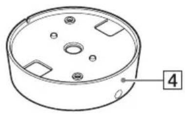
natural_image
Technical line drawing of a circular mechanical component with mounting holes and a numbered label (4) pointing to one corner.①設置スプリング
natural_image
Simple line drawing of a circular opening with concentric rings and a small circle at the center (no text or symbols)1 天井に穴を開ける。
natural_image
Diagram of a robotic device with gear and motor, showing rotational motion around a circular component (no text or symbols)②図のように設置スプリングをたたむ。
natural_image
Diagram showing a robotic arm rotating a cake with three flower-like poles, before and after rotation (no text or symbols)natural_image
Simple line drawing of a circular basin with a diagonal rod inserted into the center (no text or symbols)
は左右に 180 度回転できます。
集音する方向
集音したい方向に凸部を向ける。
natural_image
Technical line drawing showing a circular component before and after assembly, with screw fasteners inserted (no text or symbols)3 箇所の長穴を付属のネジで固定する。
natural_image
Technical line drawing of a mechanical component with concentric rings and a small circular feature (no text or symbols)natural_image
Technical line drawing of a mechanical component with a cylindrical housing and a pointer (no text or symbols)天井にワイヤー用の穴がある場合
natural_image
Mechanical gear meshing diagram showing gear shift and rotational motion (no text or labels)2 マイク本体からパネルを取りはずす。
flowchart
graph TD
    A["Motor Switch"] --> B["Switching Circuit"]
    B --> C["Battery with Cable"]
    C --> D["Electric Motor with Battery"]
natural_image
Technical diagram of a mechanical component with screws and a central hub (no text or symbols)4 マイクを天井に取り付ける。
①接続コードを天井の穴に通す。

natural_image
Technical line drawing of a mechanical component with an octagonal top and a circular base, no text or symbols present.natural_image
Technical line drawing of a mechanical component with two screws inserted, showing mounting holes and a central circular housing (no text or symbols)図のように、2か所を固定します。
natural_image
Circular mechanical component diagram with mounting holes and directional arrows (no text or symbols)5 パネルをマイクに取り付ける。
①マイク本体にパネルを合わせる。
natural_image
Technical diagram of a mechanical component with an arrow indicating assembly or insertion (no text or symbols present)flowchart
graph TD
    A["Circular Component"] --> B["Device with Pin 1"]
    B --> C["Device with Pin 2"]
    C --> D["Device with Pin 3"]
    D --> E["Device with Pin 4"]
    E --> F["Device with Pin 5"]
    F --> G["Device with Pin 6"]
    G --> H["Device with Pin 7"]
    H --> I["Device with Pin 8"]
    I --> J["Device with Pin 9"]
    J --> K["Device with Pin 10"]
メモ
マイク本体を取りはずすときは、ブラ
ケット固定ネジをはずしてから、ブラ
natural_image
Technical line drawing of a mechanical component with screw fasteners and mounting holes (no text or symbols)図のように、2か所を固定します。
natural_image
Circular mechanical component with mounting holes and directional arrows indicating rotation (no text or symbols)4 パネルをマイクに取り付ける。
* 0 dB = 1 V/Pa (1 kHz)
出力コネクター
∅ 3.5 3 極ミニプラグ
動作条件
温度 0^ 50^
湿度 20%~80%
(結露のないこと)
保存条件
温度 - 20 ℃~+ 60 ℃
湿度 20%~95%
(結露のないこと)
電源・その他
一般
For the customers in Europe
This product is intended for use in the following Electromagnetic Environments: E1 (residential), E2 (commercial and light industrial), E3 (urban outdoors), E4 (controlled EMC environment, ex. TV studio).
For the customers in the U.S.A. SONY LIMITED WARRANTY -
Please visit http://www.sony.com/psa/warranty for important information and complete terms and conditions of Sony's limited warranty applicable to this product.
For the customers in Canada SONY LIMITED WARRANTY -
Please visit http://www.sonybiz.ca/pro/lang/en/ca/article/resources-warranty for important information and complete terms and conditions of Sony's limited warranty applicable to this product.
For the customers in Europe
Sony Professional Solutions Europe - Standard Warranty and Exceptions on Standard Warranty. Please visit http://www.pro.sony.eu/warranty for important information and complete terms and conditions.
For the customers in Korea SONY LIMITED WARRANTY
Please visit http://bpeng.sony.co.kr/ handler/BPAS-Start for important information and complete terms and conditions of Sony's limited warranty applicable to this product.
Table of Contents
Features ....3
Package Contents ....4
Names and Functions of Parts .....5
Front View ....5
Rear View ......6
Installation 7
Ceiling-Recessed Installation .....7
Ceiling Projection Installation ...11
Precautions ......18
Major Specifications ....18
Trademarks
The products or system names appearing in this document are trademarks or registered trademarks of their respective owners.
Further, the ® or ™ symbols are not used in the text.
Features
The SCA-M30 Ceiling Microphone is designed with high performance and durability especially for security applications, with the following features.
Optimized for use with Sony network cameras
The SCA-M30 supports “plug-in power” (accepting dc bias voltage for the microphone through the audio cable), and provides compatible audio electrical characteristics (microphone input signal level, dynamic range and impedance).
High-fidelity design
- Supersensitive unidirectional electret condenser transducer.
- Acoustic shielding construction suppresses noise from the sides and back, while clearly picking up sounds from the front.
- Pickup direction is aimed simply by rotating the grill section.
- A low-cut filter is included to suppress low-frequency noise.
Designed to endure external vibrations
- Rubber-cushioned mounting suppresses pickup of vibration noise.
- No-hole upper case design suppresses direct noise pickup from ceiling spaces.
- Folding mounting springs suppress pickup of direct external vibrations.
Simple installation
- The microphone unit mounting springs require only a hole made with standard tools (90 mm to 100 mm ( 3^5/_8 inches to 4 inches) diameter).
- The output signal connects to the microphone input jack on a Sony Network Camera (supports 2- or 3-pin plug-in power supply).
- A bracket is provided for mounting on ceilings where a large hole (90 mm to 100 mm ( 3^5/_8 inches to 4 inches)) cannot be provided.
Selectable input sensitivity
Input level can be selected from 0 dB (H), -6 dB (M), or -12 dB (L) to match the requirements of different connected devices.
Package Contents
Check that the following items are included in this package:
- Microphone (main) unit (1) • Bracket (for ceiling installation) (1)

natural_image
Technical line drawing of a mechanical component with flanged ends and a central circular housing (no text or symbols)
natural_image
Technical line drawing of a circular mechanical component with mounting holes and internal features (no text or symbols)- Microphone mounting screws (B2.6 × 20) (3)
- Bracket mounting screws (BV4 × 20) (2)
• Operation Manual (1) - Warranty book (1)
Notes
- This package may contain additional hardware and/or documentation.
- Save the boxes and packing materials for future use.
Names and Functions of Parts
Front View
Microphone unit Bracket


natural_image
Technical line drawing of a circular mechanical component with mounting holes and a numbered label (4) pointing to one corner.1 Mounting springs
These springs hold the microphone unit in place.
To install recessed in the ceiling: Merely fold the springs and insert to secure the unit in the hole.
To remove: Pull the unit downwards.
Caution
Be careful of the springs snapping outwards when removing from the ceiling.
2 Panel
This decorative panel hides the mounting screws.
Temporarily remove the panel when mounting using the bracket or screwing directly to the ceiling.
③ Microphone direction indicator (projection)
Indicates the microphone pickup direction.
Use this marker to aim the microphone unit during mounting.
The microphone unit can still be adjusted by turning after mounting.
4 Bracket
Use when the unit cannot be mounted recessed in the ceiling.
Rear View
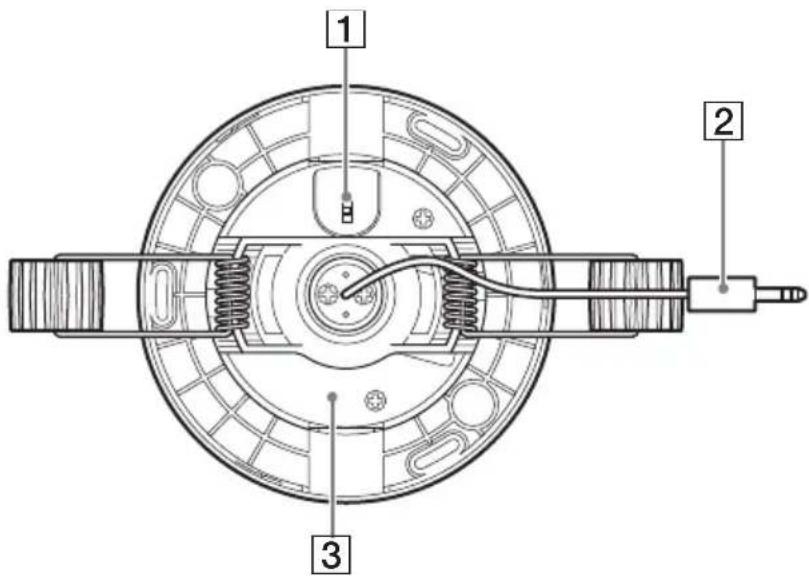
1 ATT (sensitivity setting) switch
Set this switch to select microphone input sensitivity (attenuation).
Set if needed to avoid audio clipping on the connected device, according to installation conditions.
“H” is the highest sensitivity setting.
H: 0 dB
M: approximately -6 dB
L: approximately -12 dB
“H” is the default setting.
Refer to the operation manual of the connected device for level adjustment on that device.
2 Microphone output connector/cable
Connects to a microphone input jack with “plug-in power” or equivalent bias voltage supply function.
Connect this to a device that can supply "plug-in power."
③ Microphone unit
The unit can be rotated 360 degrees.
It can be adjusted by turning after mounting.
Installation
Installation location
• Install near a corner of the room rather than at the center, to avoid other fixtures.
- The projection on the grill indicates the microphone pickup direction. Rotate the grill so that the projection points in the desired direction.
- Depending on the surroundings, sounds are picked up within about a five meter radius of the center of the pickup direction.
- For larger rooms, install multiple units.
Caution
• Install as far away as possible from air circulation systems such as air conditioners, and from other sound sources.
• Install as far away as possible from lighting fixtures.
Ceiling-Recessed Installation
Cut a hole in the ceiling, and insert the microphone.
natural_image
Simple line drawing of a circular opening with concentric rings and a central dot (no text or symbols)1 Cut a hole in the ceiling.
Mounting hole size is 90 mm to 100 mm (3 ^5 /8 inches to 4 inches) diameter.

natural_image
Pure geometric diagram of a circular ring with an arrow pointing to its center (no text or symbols)90 mm to 100 mm ( 3^5/_8 inches to 4 inches) diameter
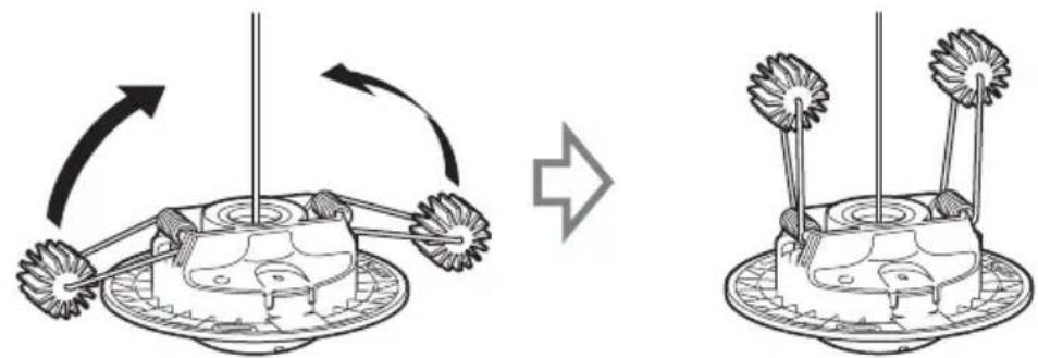
2 Insert the microphone unit into the ceiling.
①Route the cable through the hole.

natural_image
Diagram of a robotic device with rotating arm and base, showing motion flow (no text or symbols)②Fold the springs upwards as shown.

natural_image
Diagram showing a mechanical device with rotating arms and a base-mounted base, illustrating the process of rotation (no text or symbols present)③With the springs folded, push the microphone unit into the ceiling.

flowchart
graph TD
    A["Top View"] --> B["Lighting Setup"]
    B --> C["Add Top View"]
    C --> D["Add Display"]
Caution
Be careful of the springs snapping outwards when removing from the ceiling.
3 Rotate the grill to set the pickup direction.
The grill can be rotated 180 degrees in either direction.
Point the projection on the microphone unit in the desired pickup direction.
Microphone pickup direction indicator (projection)

natural_image
Simple line drawing of a circular object with concentric rings and a diagonal line extending from its center (no text or symbols)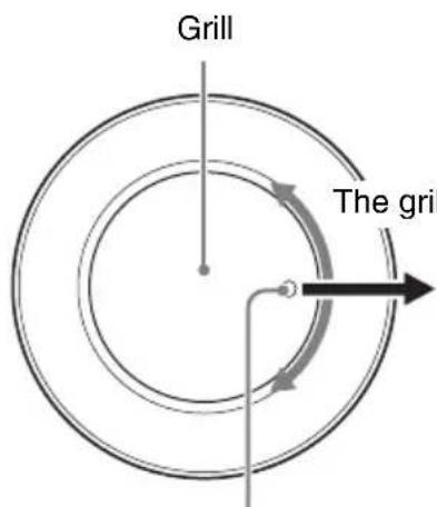
The grill can be rotated 180 degrees in either direction.
Pickup direction
Point the projection in the desired pickup direction.
4 Affix the microphone unit with screws as needed.
①Remove the panel from the microphone unit.
Push the microphone unit and, and turn the panel in the direction indicated by the arrows to remove.

②Affix the microphone unit using the supplied mounting screws (B2.6 × 20).
natural_image
Technical line drawing showing a circular component before and after assembly, with screw fasteners inserted (no text or symbols)Install the supplied screws in the three elongated holes.
③ Insert the hooks on the panel rim into the slits on the microphone unit, and turn the panel clockwise to mount.
flowchart
graph TD
    A["Original Device"] --> B{Mechanical Process}
    B --> C["Reformed Component"]
    C --> D["Final Component"]
Ceiling Projection Installation
Install using the supplied bracket.
Use one of the following installation procedures according to the mounting location.
When the ceiling has a hole for the wire (see page 12)
Install with the cable inserted through the ceiling hole.
natural_image
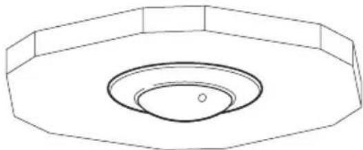
Technical line drawing of a mechanical component with concentric rings and a central hole (no text or symbols)When the ceiling has no hole for the wire (see page 16)
Install with the cable routed through the notch in the side of the bracket.

natural_image
Technical line drawing of a mechanical component with a cylindrical housing and a tool inserted (no text or symbols)When the ceiling has a hole for the wire
Attach the microphone unit to the bracket before affixing it to the ceiling.
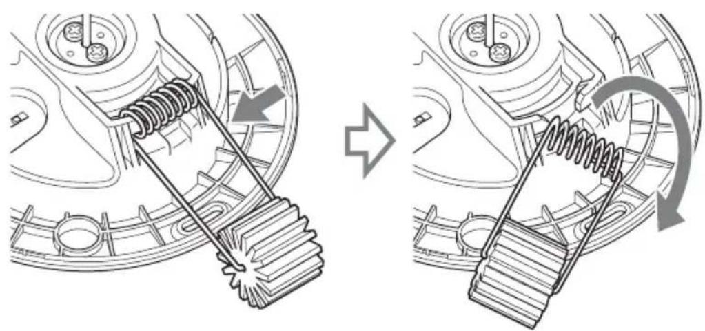
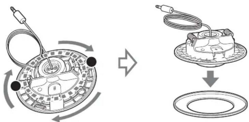
1 Remove the mounting springs from the microphone unit.
Compress the spring in the direction of the arrow below, and twist from the right side as shown to remove.
natural_image
Mechanical gear meshing diagram showing gear shift and rotational motion (no text or symbols)2 Remove the panel from the microphone unit.
Press at the points marked ● in the illustration, and turn the panel in the direction indicated by the arrows to remove.
flowchart
graph TD
    A["Left Component: Circular component with cable and connector"] --> B["Right Component: Multi-layered device with cable and connector"]
    style A fill:#f9f,stroke:#333
    style B fill:#bbf,stroke:#333
3 Insert the microphone unit into the bracket.
①Insert the cable through the hole in the bracket.

②Align the microphone unit with the bracket as shown to assemble.

Caution
Be careful to avoid pinching the cable between the bracket and the microphone unit.
③Affix the microphone unit to the bracket using the supplied screws (B2.6 × 20).

natural_image
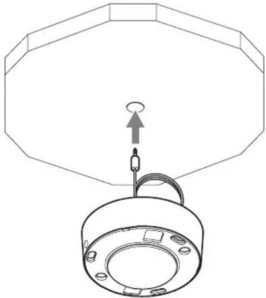
Technical line drawing of a mechanical component with screws and a handle (no text or symbols)4 Mount the assembly on the ceiling.
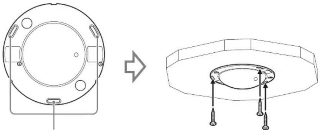
①Route the cable through the hole in the ceiling.
natural_image
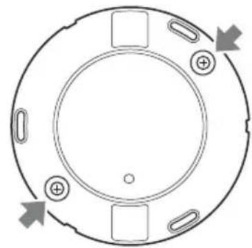
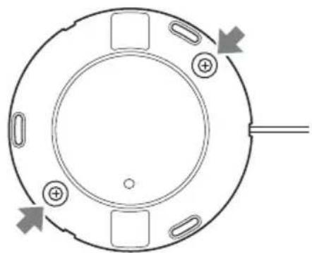
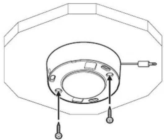
Technical line drawing of a mechanical component with an octagonal top and circular base (no text or symbols)② Affix the assembly to the ceiling using the two supplied bracket mounting screws (BV4 × 20).

natural_image
Technical line drawing of a mechanical component with screw fasteners and a central hub (no text or symbols)Insert the screws in the two places shown.

natural_image
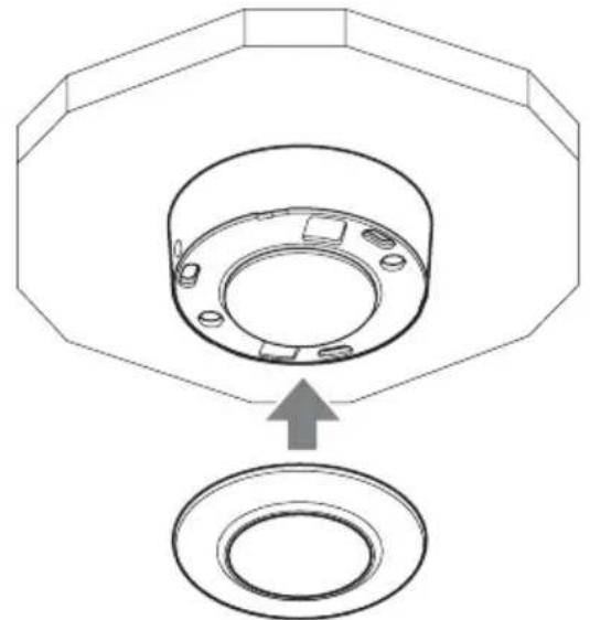
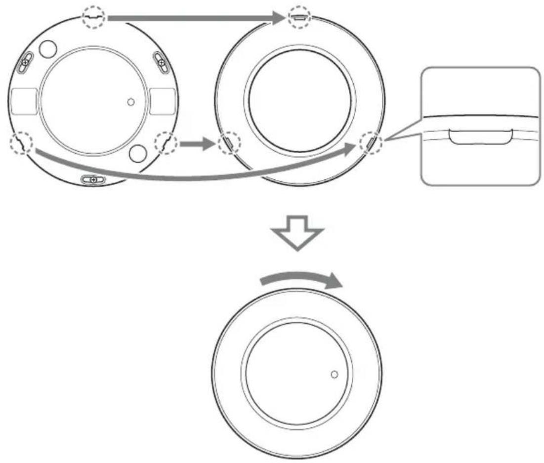
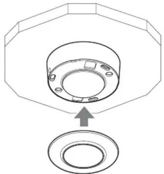
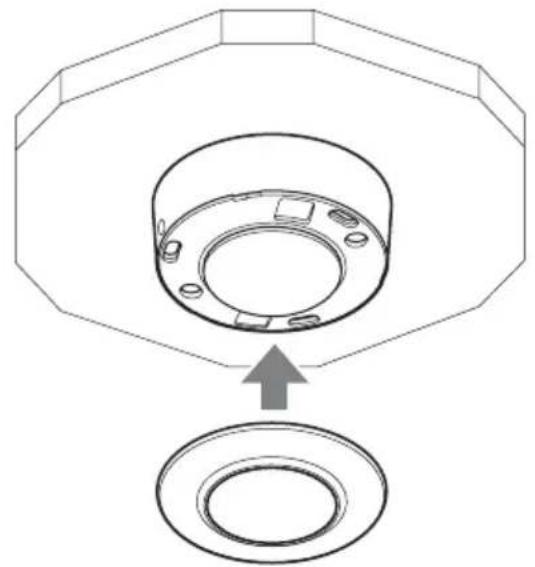
Circular mechanical component with mounting holes and directional arrows, no text or symbols present5 Install the panel over the microphone unit.
①Align the panel with the microphone unit.
natural_image
Technical diagram of a mechanical component with an arrow indicating assembly or transformation (no text or symbols present)② Insert the hooks on the rim into the slits on the microphone unit, and turn the panel clockwise to mount.

flowchart
graph TD
    A["Original Device"] --> B{Mechanical Process}
    B --> C["Reformed Component"]
    C --> D["Final Component"]
6 Rotate the grill as needed to set the microphone pickup direction.
See step 3 (page 9) of the ceiling-recessed installation procedure for details.
When the ceiling has no hole for the wire
Attach the microphone unit to the bracket before affixing it to the ceiling.
1 Remove the installation springs and panel from the microphone unit.
For details, see steps 1 and 2 of “When the ceiling has a hole for the wire” on page 12.
2 Insert the microphone unit into the bracket.
①Insert the cable through the hole in the bracket.

②Align the microphone unit with the bracket and route the cable through the notch in the bracket.
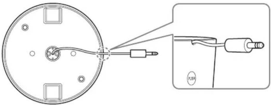
Note
When dismounting the microphone, remove the bracket mounting screws and press the areas marked PUSH on both sides of the bracket.

3 Mount the assembly on the ceiling.
Mount the assembly on the ceiling using the two supplied bracket mounting screws (BV4 × 20).
natural_image
Technical line drawing of a mechanical component with screw fasteners and mounting holes (no text or symbols)Insert the screws in the two places shown.

natural_image
Circular mechanical component with mounting holes and directional arrows indicating rotation (no text or symbols)4 Install the panel over the microphone unit.
For details, see step 5 of "When the ceiling has a hole for the wire" on page 15.
5 Rotate the grill to set the microphone pickup direction.
See step 3 (page 9) of the ceiling-recessed installation procedure for details.
Precautions
Locations for use/storage
To prolong the life of the product, avoid use or storage in the following locations.
- Locations that can become extremely hot or cold. (Operating temperature: 0^ to 50^ (32 °F to 122 °F))
- Locations exposed for an extended time to direct sunlight, and locations near heating appliances.
- Locations with high levels of humidity or dust
- Locations subject to strong vibrations
- Locations subject to strong magnetic fields
- Locations in the vicinity of radio or TV transmitters creating a strong magnetic field
Protect from shocks and vibrations
Do not drop the strong shock, because the unit can be damaged.
Maintenance
For cleaning, lightly wipe the cabinet and panels with a dry cloth. To remove stubborn stains, lightly moisten the cloth with a mild, neutral detergent and wipe with a dry cloth afterwards. Do not use cleaning alcohol, solvents, benzine, insecticide, or any other volatile substances, because these may damage the finish and lead to discoloration.
Transport
Use the original packing material or similar packing to protect the unit from shocks.
Major Specifications
Microphone
Type Electret condenser
microphone
Frequency response
300 Hz to 10,000 Hz
Directivity Un-idirectional
Sensitivity -35 dB ± 3.5 dB
S/N ratio 60 dB or more
* 0 dB = 1 V/Pa (1 kHz)
Output Connector
3.5 mm diameter
3-pole mini plug
Operating Environment
Temperature 0 °C to 50 °C
(32 °F to 122 °F)
Humidity 20% to 80%
(non-condensating)
Storage Environment
Temperature -20^ to +60^
(-4^ to +140^)
Humidity 20% to 95%
(non-condensating)
Power Requirement and Miscellaneous
General
Supply voltage 1.5 V to 9 V
(Plug-in power)
Current consumption
0.5 mA or less
Size 132 mm dia. ×60 mm
$$ (5 ^ {1} / _ {4} \text {in.} \times 2 ^ {3} / _ {8} \text {in.}) $$
(with bracket)
$$ 1 2 6 \mathrm{mm} \text { dia. } \times 5 5 \mathrm{mm} $$
$$ (5 \text { in. } \times 2 ^ {- 1} / _ {4} \text { in. }) $$
(without bracket)
Weight Approx. 225 g (7.9 oz.)
(with bracket)
$$ \text { Approx. } 1 7 0 \mathrm{g} (6. 0 \text { oz. }) $$
(without bracket)
Accessories
Bracket (1)
Microphone Mounting Screws (B2.6×20) (3)
Bracket Mounting Screws (BV4 × 20) (2)
Operating Instructions (1)
Warranty book (1)
Design and specifications are subject to change without notice.
Note
Always verify that the unit is operating properly before use. SONY WILL NOT BE LIABLE FOR DAMAGES OF ANY KIND INCLUDING, BUT NOT LIMITED TO, COMPENSATION OR REIMBURSEMENT ON ACCOUNT OF THE LOSS OF PRESENT OR PROSPECTIVE PROFITS DUE TO FAILURE OF THIS UNIT, EITHER DURING THE WARRANTY PERIOD OR AFTER EXPIRATION OF THE WARRANTY, OR FOR ANY OTHER REASON WHATSOEVER.
Recommendation of Periodic Inspections
In case using this device over an extended period of time, please have it inspected periodically for safe use.
It may appear flawless, but the components may have deteriorated over time, which may cause a malfunction or accident.
For details, please consult the store of purchase or an authorized Sony dealer.
natural_image
Technical line drawing of a mechanical component with flanged ends and a central circular housing (no text or symbols)
natural_image
Technical line drawing of a circular mechanical component with mounting holes and internal features (no text or symbols)
natural_image
Technical line drawing of a circular mechanical component with mounting holes and a numbered label (4) pointing to one corner.natural_image
Pure technical line drawing of a circular component with concentric rings and a central hole (no text or symbols)natural_image
Pure technical line drawing of a circular component with an arrow pointing to its center (no text or symbols)natural_image
Diagram of a robotic device with rotating arm and base, showing motion flow (no text or symbols)natural_image
Diagram showing a robotic arm interacting with a cake, before and after rotation (no text or symbols)natural_image
Simple line drawing of a circular basin with a diagonal rod inserted into the center (no text or symbols)Grillage

natural_image
Technical line drawing showing a circular component before and after assembly, with screw fasteners inserted (no text or symbols)natural_image
Technical line drawing of a mechanical component with concentric rings and a central hole (no text or symbols)natural_image
Technical line drawing of a mechanical component with a cylindrical body and a pointer, enclosed in an octagonal frame (no text or symbols)natural_image
Mechanical gear meshing diagram showing gear shift and rotational motion (no text or symbols)Précaution
natural_image
Technical line drawing of a mechanical component with screws and a curved housing (no text or symbols)natural_image
Technical line drawing of a mechanical component with an octagonal frame and a circular base (no text or symbols)natural_image
Technical line drawing of a mechanical component with screw fasteners and a circular housing (no text or symbols)natural_image
Circular mechanical component with mounting holes and directional arrows indicating rotation (no text or symbols)natural_image
Technical diagram of a mechanical component with an arrow indicating assembly or insertion (no text or symbols present)natural_image
Diagram showing a circular component connected to a connector with a USB cable, plus an inset view of the cable being inserted (no text or symbols present)Remarque
natural_image
Technical line drawing of a mechanical component with screw fasteners and mounting holes (no text or symbols)natural_image
Circular mechanical component with mounting holes and directional arrows indicating rotation (no text or symbols)* 0 dB = 1 V/Pa (1 kHz)
Approx. 170 g (6,0 on.)
(sans support)
Accessoires
Support (1)
natural_image
Technical line drawing of a mechanical component with flanged ends and a central circular housing (no text or symbols)
natural_image
Technical line drawing of a circular mechanical component with mounting holes and internal features (no text or symbols)natural_image
Technical line drawing of a circular mechanical component with mounting holes and a numbered label (4) pointing to one corner.1 Interruptor ATT (ajuste de sensibilidad)
natural_image
Pure technical line drawing of a circular component with concentric rings and a central hole (no text or symbols)natural_image
Simple line drawing of a circular object with an arrow pointing to its center (no text or symbols)natural_image
Diagram of a robotic device with rotating arm and base, showing motion flow (no text or symbols)natural_image
Diagram showing a mechanical device rotating around a cake with two flower-like structures, before and after rotation (no text or symbols)natural_image
Simple line drawing of a circular basin with a diagonal rod inserted into the center (no text or symbols)
natural_image
Technical line drawing showing a circular component before and after assembly, with screw fasteners inserted (no text or symbols)natural_image
Technical line drawing of a mechanical component with concentric rings and a central hole (no text or symbols)natural_image
Technical line drawing of a mechanical component with a cylindrical housing and a pointer (no text or symbols)flowchart
graph TD
    A["Motor Switch"] --> B["Switching Circuit"]
    B --> C["Battery with Sensor"]
    C --> D["Electric Motor with Cable"]
    D --> E["Battery with Sensor"]
    E --> F["Electric Motor with Cable"]
natural_image
Technical line drawing of a mechanical component with screws and a curved housing (no text or symbols)natural_image
Technical line drawing of a mechanical component with an octagonal frame and a circular base (no text or symbols)natural_image
Technical line drawing of a mechanical component with screw fasteners and a circular housing (no text or symbols)natural_image
Circular mechanical component with mounting holes and directional arrows indicating rotation (no text or symbols)natural_image
Technical diagram of a mechanical component with an arrow indicating assembly or insertion (no text or symbols present)natural_image
Technical diagram showing a circular component connected to a cable with a connector, and a close-up of a cable being inserted into a socket (no text or symbols present)Nota
natural_image
Technical line drawing of a mechanical component with screw fasteners and mounting holes (no text or symbols)natural_image
Circular mechanical component with mounting holes and directional arrows indicating rotation (no text or symbols)natural_image
Technical line drawing of a mechanical component with flanged ends and a central circular housing (no text or symbols)
natural_image
Technical line drawing of a circular mechanical component with mounting holes and a central hub (no text or symbols)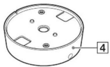
natural_image
Technical line drawing of a circular mechanical component with mounting holes and a numbered label (4) pointing to one corner.1 Montagefedern
natural_image
Simple line drawing of a circular opening with concentric rings and a small circle inside (no text or symbols)natural_image
Simple line drawing of a circular object with an arrow pointing to its center (no text or symbols)natural_image
Diagram showing a mechanical device with rotating components and a curved arrow indicating rotation (no text or symbols)natural_image
Diagram showing a robotic arm interacting with a cake, before and after rotation (no text or symbols)flowchart
graph TD
    A["Top View"] --> B["Side View"]
    B --> C["Bottom View"]
Vorsicht
natural_image
Simple line drawing of a circular object with concentric rings and a diagonal line extending from its center (no text or symbols)Gitter

natural_image
Technical line drawing showing a circular component before and after assembly, with screw fasteners inserted (no text or symbols)natural_image
Technical line drawing of a mechanical component with concentric circular features and a small hole (no text or symbols)natural_image
Technical line drawing of a mechanical component with a cylindrical housing and a pointer (no text or symbols)natural_image
Mechanical gear meshing diagram showing gear shift and rotational motion (no text or labels)flowchart
graph TD
    A["Motor with cable"] --> B["Switch"]
    B --> C["Capacitor with switch"]
    C --> D["Electric motor with cable"]
    D --> E["Load capacitor with ring"]
natural_image
Technical diagram of a mechanical component with screws and a curved housing (no text or symbols)natural_image
Technical line drawing of a mechanical component with an octagonal top and circular base, showing a cable and connector (no text or symbols)natural_image
Technical line drawing of a mechanical component with screw fasteners and a circular housing (no text or symbols)natural_image
Circular mechanical component with four mounting holes and directional arrows indicating rotation (no text or symbols)natural_image
Technical diagram of a mechanical component with an arrow indicating assembly or transformation (no text or symbols present)natural_image
Technical diagram showing a circular component connected to a connector with a cable, plus an inset view of a cable being inserted (no text or symbols present)Hinweis
natural_image
Technical line drawing of a mechanical component with screw fasteners and mounting holes (no text or symbols)natural_image
Circular mechanical component with mounting holes and directional arrows indicating rotation (no text or symbols)* 0 dB = 1 V/Pa (1 kHz)
Ausgangsanschluss
natural_image
Technical line drawing of a mechanical component with flanged ends and a central circular housing (no text or symbols)
natural_image
Technical line drawing of a circular mechanical component with mounting holes and a central hub (no text or symbols)natural_image
Technical line drawing of a circular mechanical component with mounting holes and a numbered label (4) pointing to one corner.natural_image
Simple line drawing of a circular opening with concentric rings and a small circle at the center (no text or symbols)natural_image
Simple line drawing of a circular object with an arrow pointing to its center (no text or symbols)Diametro da 90 mm a 100 mm (da 3 ^5 / _8 pollici a 4 pollici)
natural_image
Diagram of a robotic device with rotating arm and base, showing motion flow (no text or symbols)natural_image
Diagram showing a mechanical device rotating around a cake with two flower-like structures, before and after rotation (no text or symbols)natural_image
Simple line drawing of a circular basin with a diagonal rod inserted into the center (no text or symbols)
natural_image
Technical line drawing showing a circular component before and after assembly, with screw fasteners inserted (no text or symbols)natural_image
Technical line drawing of a mechanical component with concentric rings and a central hole (no text or symbols)natural_image
Technical line drawing of a mechanical component with a cylindrical body and a pointer, enclosed in an octagonal frame (no text or symbols)natural_image
Mechanical gear assembly diagram showing gear meshing before and after disassembly (no text or labels)flowchart
graph TD
    A["Motor with cable"] --> B["Switch with motor"]
    B --> C["Capacifier with battery"]
    C --> D["Load back to fan"]
natural_image
Technical line drawing of a mechanical component with screws and a curved housing (no text or symbols)natural_image
Technical line drawing of a mechanical component with an octagonal frame and a circular base (no text or symbols)natural_image
Technical line drawing of a mechanical component with screw fasteners and a circular housing (no text or symbols)natural_image
Circular mechanical component with mounting holes and directional arrows indicating rotation (no text or symbols)natural_image
Technical diagram of a mechanical component with an arrow indicating assembly or insertion (no text or symbols present)flowchart
graph TD
    A["Circular Component"] --> B["Device with Pin 1"]
    B --> C["Device with Pin 2"]
    C --> D["Device with Pin 3"]
    D --> E["Device with Pin 4"]
    E --> F["Device with Pin 5"]
    F --> G["Device with Pin 6"]
    G --> H["Device with Pin 7"]
    H --> I["Device with Pin 8"]
    I --> J["Device with Pin 9"]
    J --> K["Device with Pin 10"]
natural_image
Diagram showing a circular device connected to a cable with a switch, alongside an exploded view of its cable assembly (no text or symbols present)Nota
natural_image
Technical line drawing of a mechanical component with screw fasteners and mounting holes (no text or symbols)natural_image
Circular mechanical component with mounting holes and directional arrows indicating rotation (no text or symbols)natural_image
Technical line drawing of a mechanical component with flanged ends and a central circular housing (no text or symbols)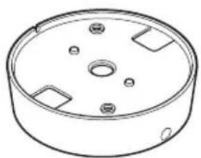
natural_image
Technical line drawing of a circular mechanical component with mounting holes and internal features (no text or symbols)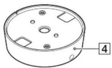
natural_image
Technical line drawing of a circular mechanical component with mounting holes and a numbered label (4) pointing to one corner.1고정 스프링
본체 고정용 스프링입니다.
1ATT(감도 설정)스위치
natural_image
Pure technical line drawing of a mechanical component with concentric circular features (no text or symbols)1 천장에 구멍을 뜻습니다.
natural_image
Pure geometric diagram of a circular ring with an arrow pointing to its center (no text or symbols)natural_image
Diagram of a robotic device with gear and motor, connected to a circular component (no text or symbols)natural_image
Diagram showing a robotic arm rotating a cake with three flower-like poles, before and after rotation (no text or symbols)flowchart
graph TD
    A["Top View"] --> B["Light Fixture with Top"]
    B --> C["Top View with Top"]
    C --> D["Final Display"]
주의
natural_image
Simple line drawing of a circular basin with a diagonal rod inserted into the center (no text or symbols)
natural_image
Technical line drawing showing a circular component before and after assembly, with screw fasteners inserted (no text or symbols)natural_image
Technical line drawing of a mechanical component with concentric rings and a central hole (no text or symbols)natural_image
Technical line drawing of a mechanical component with a cylindrical body and a pointer, enclosed in an octagonal frame (no text or symbols)천장에 배선용 구멍이 있을 때
natural_image
Mechanical assembly diagram showing gear meshing before and after disassembly (no text or symbols)2 마이크에서 패널을 분리합니다.
flowchart
graph TD
    A["Motor with cable"] --> B["Switch"]
    B --> C["Capacitor with diode"]
    C --> D["Motor with cable"]
    D --> E["Capacitor with diode"]
    E --> F["Output"]
3 마이크를 브래킷에 삽입합니다.
natural_image
Technical line drawing of a mechanical component with screws and a curved housing (no text or symbols)natural_image
Technical line drawing of a ceiling-mounted device with an octagonal frame and cable (no text or symbols)natural_image
Technical line drawing of a mechanical component with two screws inserted, showing mounting holes and a central circular housing (no text or symbols)natural_image
Circular mechanical component diagram with mounting holes and directional arrows (no text or symbols)5 마이크에 패널을 부착합니다.
①패널을 마이크와 맞춤니다.
natural_image
Technical diagram of a mechanical component with an arrow indicating assembly or insertion (no text or symbols present)flowchart
graph TD
    A["Top Circular Component"] --> B["Bottom Circular Component"]
    B --> C["Assembly Step"]
    C --> D["Final Ring with Down Arrow"]
natural_image
Technical diagram showing a circular component connected to a connector with a cable, alongside an inset close-up of a cable being inserted (no text or symbols present)참고
natural_image
Technical line drawing of a mechanical component with screws and a central hub (no text or symbols)natural_image
Circular mechanical component with mounting holes and directional arrows indicating rotation (no text or symbols)4 마이크에 패널을 부착합니다.
* 0 dB = 1 V/Pa (1 kHz)
출력 커넥터


- 天井に穴を開ける。
- 天井にワイヤー用の穴がある場合
- マイク本体からパネルを取りはずす。
- マイクを天井に取り付ける。
- パネルをマイクに取り付ける。
- メモ
- パネルをマイクに取り付ける。
- 出力コネクター
- 動作条件
- 保存条件
- 電源・その他
- 一般
- For the customers in Europe
- For the customers in the U.S.A. SONY LIMITED WARRANTY -
- For the customers in Canada SONY LIMITED WARRANTY -
- For the customers in Korea SONY LIMITED WARRANTY
- Table of Contents
- Trademarks
- Features
- Optimized for use with Sony network cameras
- High-fidelity design
- Designed to endure external vibrations
- Simple installation
- Selectable input sensitivity
- Package Contents
- Notes
- Names and Functions of Parts
- Front View
- Mounting springs
- Caution
- Panel
- ③ Microphone direction indicator (projection)
- Bracket
- Rear View
- ATT (sensitivity setting) switch
- Microphone output connector/cable
- ③ Microphone unit
- Installation
- Installation location
- Ceiling-Recessed Installation
- Cut a hole in the ceiling.
- Insert the microphone unit into the ceiling.
- Rotate the grill to set the pickup direction.
- Affix the microphone unit with screws as needed.
- Ceiling Projection Installation
- When the ceiling has a hole for the wire (see page 12)
- When the ceiling has no hole for the wire (see page 16)
- When the ceiling has a hole for the wire
- Remove the mounting springs from the microphone unit.
- Remove the panel from the microphone unit.
- Insert the microphone unit into the bracket.
- Mount the assembly on the ceiling.
- Install the panel over the microphone unit.
- Rotate the grill as needed to set the microphone pickup direction.
- When the ceiling has no hole for the wire
- Remove the installation springs and panel from the microphone unit.
- Insert the microphone unit into the bracket.
- Note
- Mount the assembly on the ceiling.
- Install the panel over the microphone unit.
- Rotate the grill to set the microphone pickup direction.
- Precautions
- Locations for use/storage
- Protect from shocks and vibrations
- Maintenance
- Transport
- Major Specifications
- Microphone
- Output Connector
- Operating Environment
- Storage Environment
- Power Requirement and Miscellaneous
- General
- Accessories
- Recommendation of Periodic Inspections
- Précaution
- Remarque
- Accessoires
- Nota
- Montagefedern
- Vorsicht
- Hinweis
- Ausgangsanschluss
- 1ATT(감도 설정)스위치
- 주의
- 천장에 배선용 구멍이 있을 때
- 참고
- 출력 커넥터
Brand : SONY
Model : SCAM30
Category : Microphone