Orelia Design2 900 - Basket ROBLIN - Free user manual and instructions
Find the device manual for free Orelia Design2 900 ROBLIN in PDF.

User questions about Orelia Design2 900 ROBLIN
0 question about this device. Answer the ones you know or ask your own.
Ask a new question about this device
Download the instructions for your Basket in PDF format for free! Find your manual Orelia Design2 900 - ROBLIN and take your electronic device back in hand. On this page are published all the documents necessary for the use of your device. Orelia Design2 900 by ROBLIN.
USER MANUAL Orelia Design2 900 ROBLIN
Instructions for use and installation
Cooker Hood
DE
natural_image
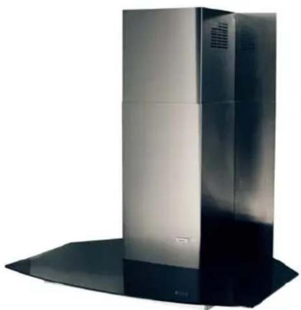
Exterior view of a modern stainless steel HVAC unit with ventilation grilles (no text or symbols visible)Orelia Design
natural_image
Exterior view of a stainless steel kitchen range hood with ventilation grilles and a black base (no text or symbols visible)Odalia
F SOMMAIRE
RACCORDEMENT ÉLECTRIQUE
CONSEILS D'INSTALLATIONS
POSE DE L'APPAREIL
FONCTIONNEMENT
CONSEILS D'UTILISATIONS
ENTRETIEN
GARANTIE ET SERVICE APRÈS-VENTE
REMARQUES
GB CONTENTS
ELECTRICAL WIRING
INSTALLATION ADVICE
FITTING THE APPLIANCE
OPERATION
USEFUL HINTS
MAINTENANCE
GUARANTEE AND AFTER-SALES-SERVICES
REMARKS
D INHALT
NETZANsCHLUSS
MONTAGEHILFEN
MONTAGE DES GERÄTES
BETRIEB DES GERÄTES
NUTZUNG
Thank you for buying a FRANKE product which has been manufactured to the highest quality standards to meet your requirements.
We recommend you carefully read this booklet in which you will find instructions for installation, hints for use and maintenance.
The Instructions for Use apply to several versions of this appliance. Accordingly, you may find descriptions of individual features that do not apply to your specific appliance.
1 ELECTRICAL
- This cooker hood is fitted with a 3-core mains cable with a standard 10/16A earthed plug.
- Alternatively the hood can be connected to the mains supply via a double-pole switch having 3mm minimum contact gap on each pole.
- Before connecting to the mains supply ensure that the mains voltage corresponds to the voltage on the rating plate inside the cooker hood.
- Technical Specification: Voltage 220-240 V, single phase \~ 50 Hz / 220 V - 60Hz.
2 INSTALLATION ADVICE
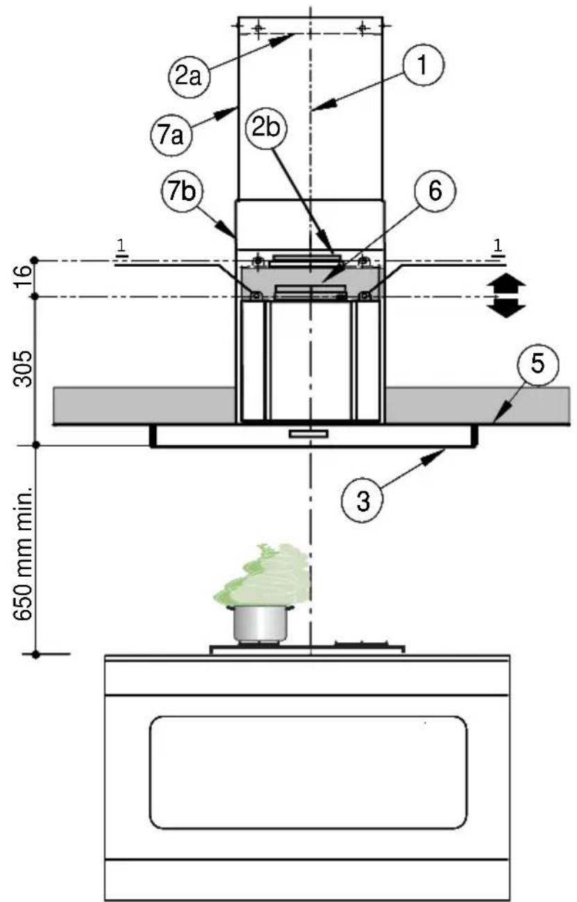
- Ensure the cooker hood is fitted in compliance with the recommended fixing heights.
- To ensure the safe operation of this cooker hood, we recommend that the hood should not be fitted below 65cm (for electric) or (70cm for gas) the measurements taken from the surface of the cooking appliance to the underside of the cooker hood.
- It is a possible fire risk if the hood is not sited as recommended.
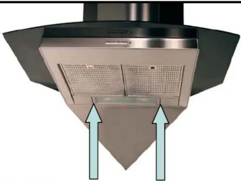
- To ensure the best results, the cooking fumes should be able to rise naturally towards the inlet grilles on the underside of the cooker hood and the cooker hood should be positioned away from doors and windows, which will create turbulence.
- Ducting
- If the room where the hood is to be used contains a fuel-burning appliance such as a central heating boiler then its flue must be of the room sealed or balanced flue type.
- If other types of flue or appliances are fitted ensure that there is an adequate supply of fresh air to the room. Ensure the kitchen is fitted with an airbrick, which should have a cross-sectional measurement equivalent to the diameter of the ducting being fitted, if not larger.
- The ducting system for this cooker hood must not be connected to any existing ventilation system, which is being used for any other purposes or to a mechanically controlled ventilation ducting.
- The ducting used must be made from fire retardant materials and the correct diameter must be used, as incorrect sized ducting will affect the performance of this cooker hood.
- When the cooker hood is used in conjunction with other appliances supplied with energy other than electricity, the negative pressure in the room must not exceed 0.04 mbar to prevent the fumes from combustion being drawn back into the room.
- The appliance is for domestic use only and should not be operated by children or people who are infirm without supervision.
- This appliance must be positioned so that the wall socket is accessible.
- This appliance is not intended for use by persons (including children) with reduced physical, sensory or mental capabilities, or lack of experience and knowledge, unless they have been given supervision or instruction concerning use of the appliance by a person responsible for their safety.
Children should be supervised to ensure that they do not play with the appliance.
3 FITTING
Any permanent electrical installation must comply with the latest regulations concerning this type of installation and a qualified electrician must carry out the work. Non-compliance could cause serious accidents or injury and would deem the manufacturers guarantee null and void.
IMPORTANT - The wires in this mains lead are coloured in accordance with the following code :
green / yellow : earth blue : neutral brown : live
As the colours of the wires in the mains lead of this appliance may not correspond with the coloured markings identifying the terminals in your plug, proceed as follows.
- The wire which is coloured green and yellow must be connected to the terminal in the plug which is marked with the letter E or by the earth symbol 12 or coloured green or green and yellow.
- The wire which is coloured blue must be connected to the terminal which is marked with the letter N or coloured black.
- The wire which is coloured brown must be connected to the terminal which is marked with the letter L or coloured red.
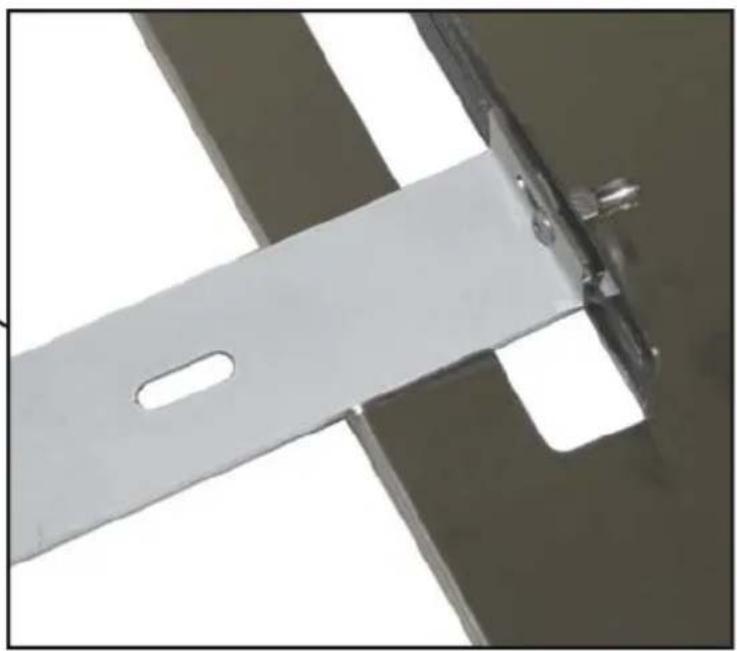
ATTENTION: Do not forget to use adequate plugs to the support brackets. Enquire after the manufacturers. Do an embedding if necessary. The manufacturer accepts no responsibility in case of a faulty hanging due to the drilling and the setting up of plugs.
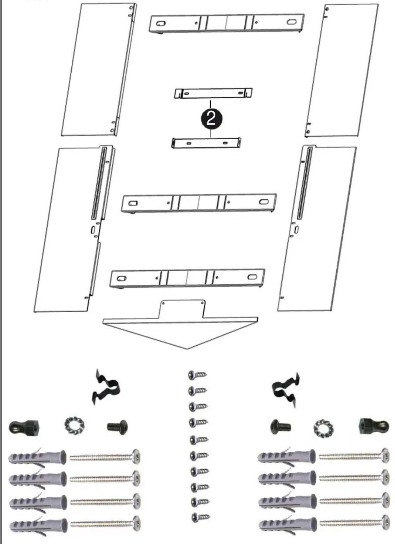
1) To carry out all the numbered operations from 1 to 16 as described starting from page 46.
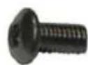
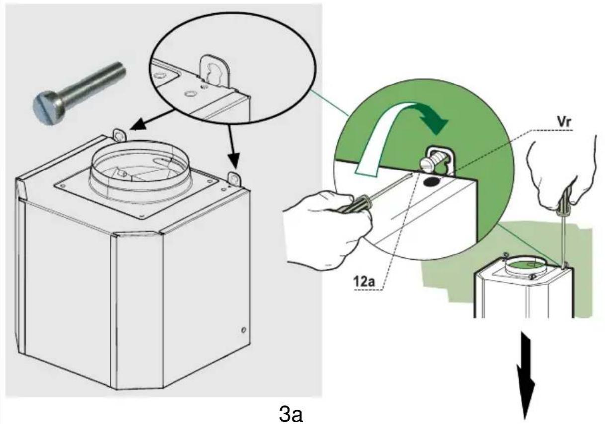
2) Fixing the canopy: Before starting to fix the canopy it will be necessary to adjust the support brackets by turning the adjustment screws Vr in a clockwise direction until their reach their limit (Fig.3a & b). Small adjustments can be made using the hood adjustment screws. The hood should have a maximum excursion of 16 mm. Hook the canopy onto the two size 4.2 x 44.4 screws 1 fitted as described above (point 12). Level the hood by turning the adjustment screws and then locking the screws 1.
3) Ducting:
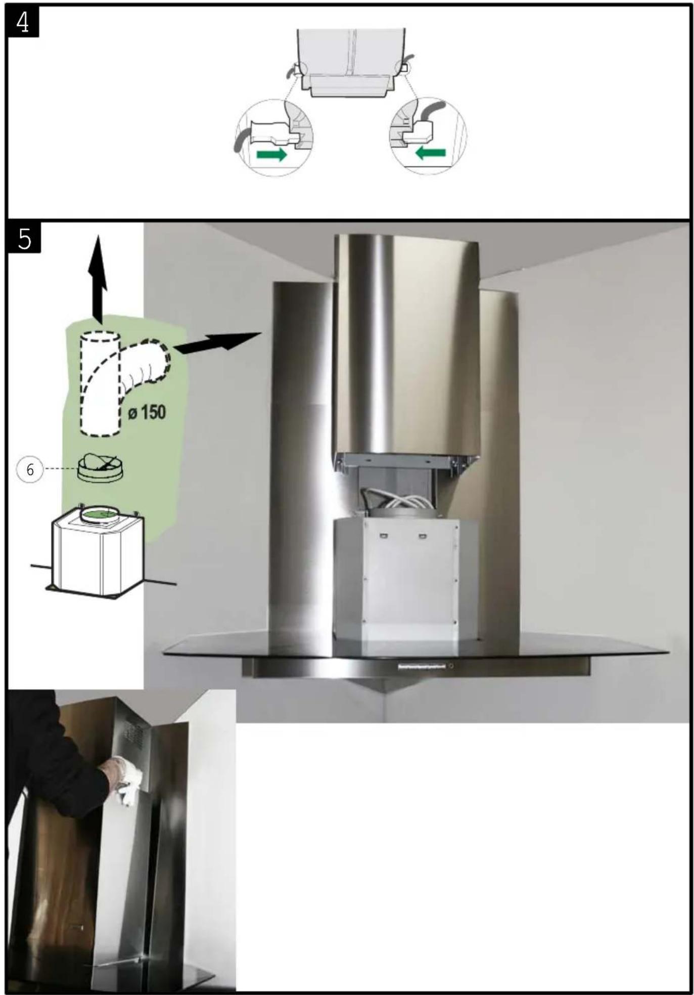
The hood is more effective when used in the extraction mode (ducted to the outside). When the cooker hood is ducted to the outside, charcoal filters are not required. The ducting used must be 150 mm (6 INS), rigid circular pipe and must be manufactured from fire retardant material, produced to BS.476 or DIN 4102-B1. Wherever possible use rigid circular pipe which has a smooth interior, rather than the expanding concertina type ducting.
Maximum length of ducting run:
- 4 metres with 1 x 90° bend.
- 3 metres with 2 x 90° bends.
- 2 metres with 3 × 90^ bends.
The above assumes our 150 mm (6 INS) ducting is being installed. Please note ducting components and ducting kits are optional accessories and have to be ordered, they are not automatically supplied with the chimney hood.
IN THE EXTRACTION MODE:
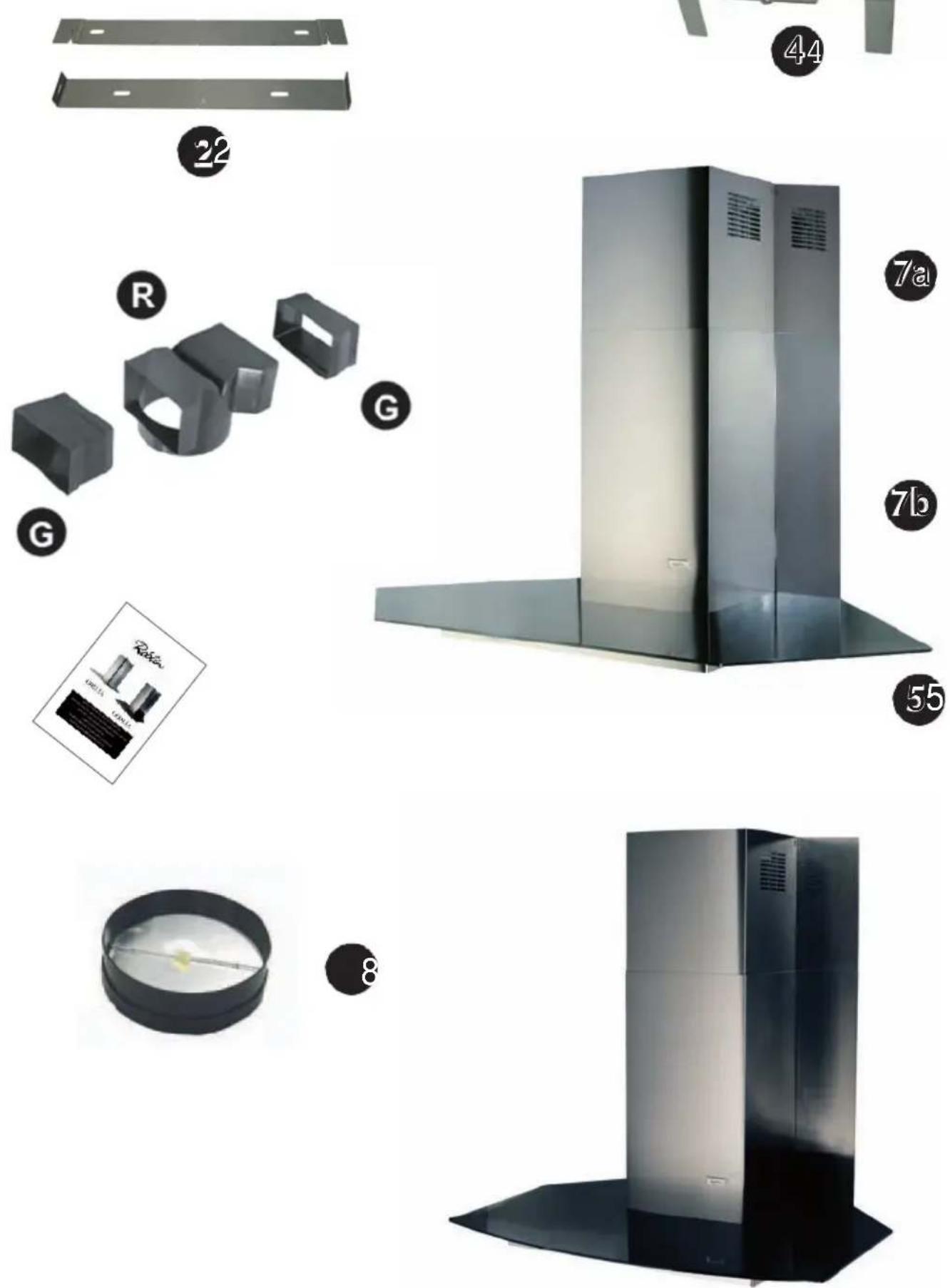
a. Place the anti-backflow flats item 8 over the round outlet item 6 and connect the ducting 150mm (6 INS) over the round outlet item 6 on top of the canopy and secure the connections with appropriate clamping rings or adhesive tape (Fig. 5).
b. Remove the grease filters (see paragraph Maintenance) being sure that the connector of the mains cable is correctly inserted in the socket placed on the side of the fan. Before fitting the chimney to the canopy make the electrical connection as described in the section titled ELECTRICAL. When the electrical connection has been made, test the lights and the fan motor.
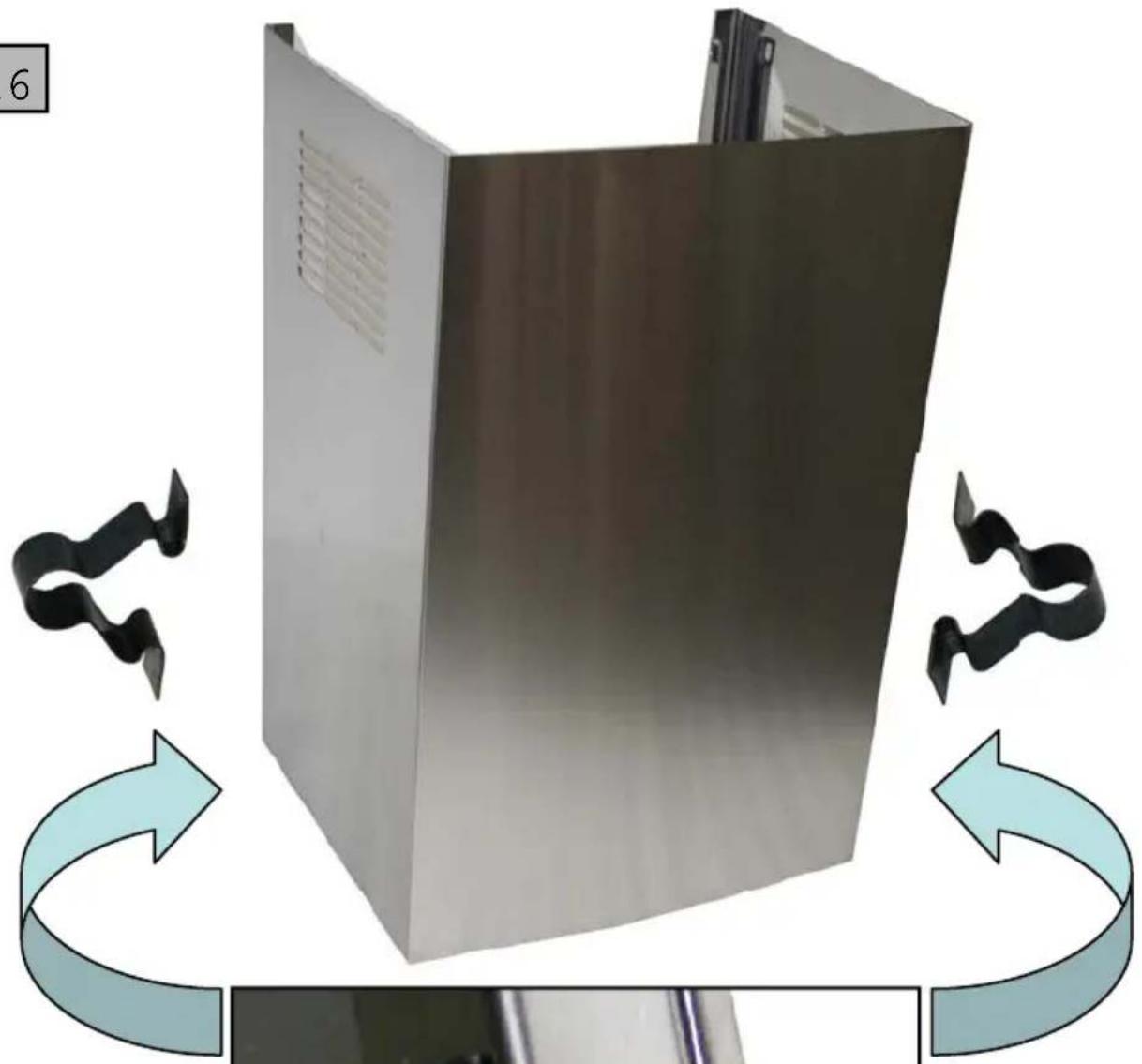
c. Upper chimney stack
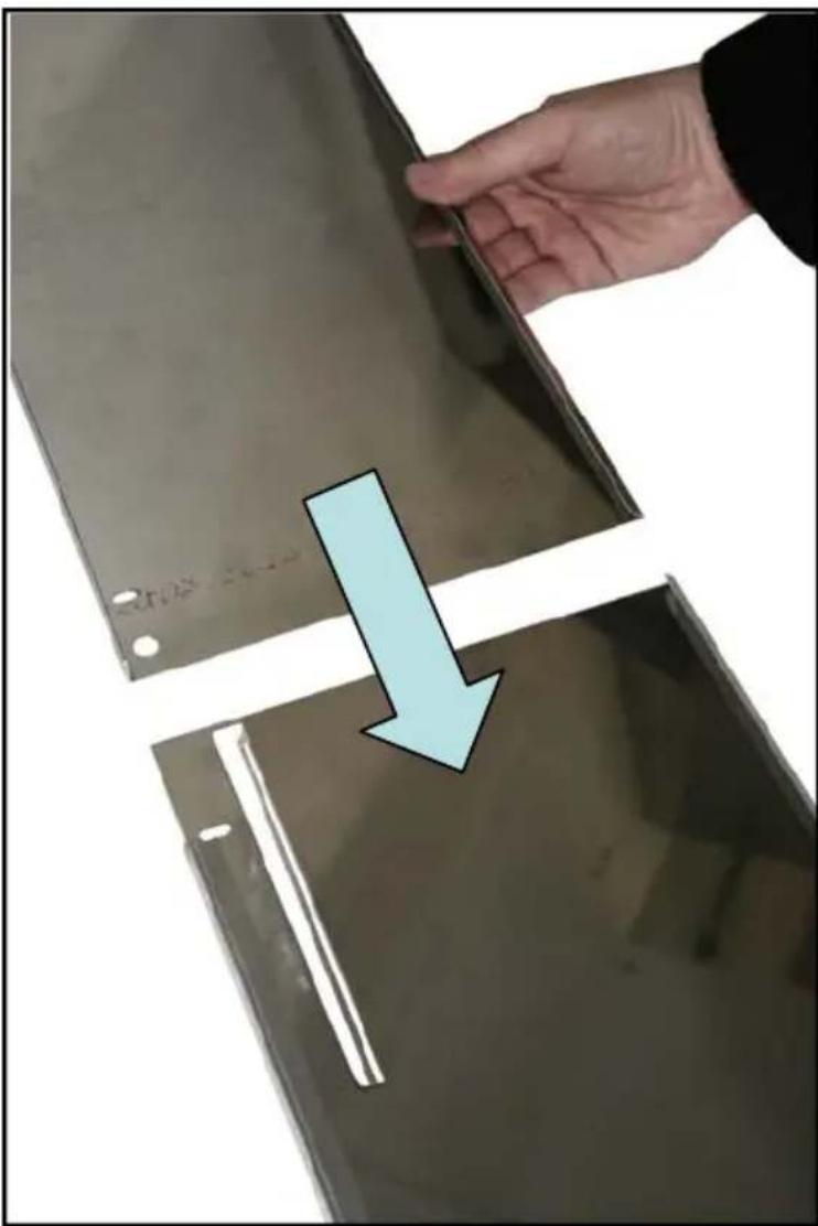
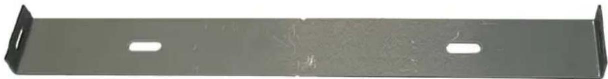
- to urge the higher edge of the two sides of the upper chimney stack in the slits of the bracket (Point 17). Slightly widen the two sides of the upper chimney stack (Fig.5 - Item 7a) and hook them behind the brackets item 2 making sure that they are well seated.
d. Lower chimney stack
- Slightly widen the two sides of the chimney stack (Fig. 5 - Item 7b) and hook them between the upper chimney stack and the wall, making sure that they are well seated.
IN THE RECIRCULATION MODE:
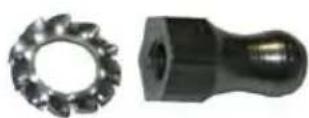
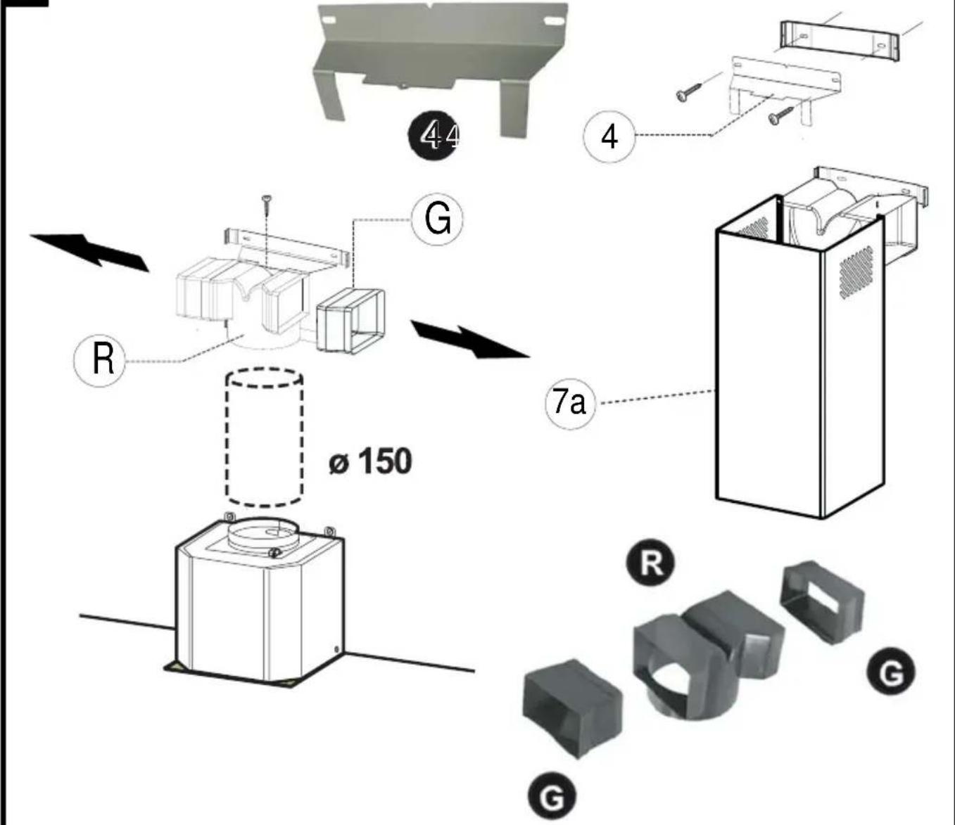
a. Fit the recirculation spigot bracket item 4 onto the upper chimney wall bracket using the same fixing screws (Fig.7 - item 2). Put the spigot item R into the spigot bracket item 4• Insert the connection
extension pieces laterally item G in the spigot. Make sure that the outlet of the extension pieces item G is horizontally and vertically aligned with the chimney outlets.
b. Connect the ducting 150mm (6 INS) not provided between motors item 6 and the recirculation spigot and secure the connections with appropriate clamping rings or adhesive tape.
c. Remove the grease filters (see paragraph Maintenance) being sure that the connector of the feeding cable is correctly inserted in the socket placed on the side of the fan. Before fitting the chimney to the canopy make the electrical connection as described in the section titled ELECTRICAL. When the electrical connection has been made, test the lights and the fan motor.
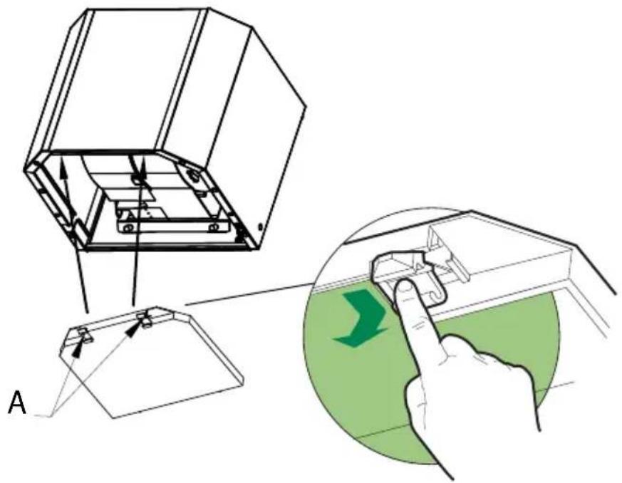
d. Remove the metal grease filters and insert the charcoal filter into the base of the motor housing and secure the filter with two metal securing straps item A as illustrated in Fig. 8.
e. Upper chimney stack
To urge the higher edge of the two sides of the upper chimney stack in the slits of the bracket (Point 17). Slightly widen the two sides of the upper chimney stack (Fig.5 - Item 7a) and hook them behind the brackets item 2 making sure that they are well seated.
f. Lower chimney stack
Slightly widen the two sides of the chimney stack (Fig. 7 - Item 7b) and hook them between the upper chimney stack and the wall, making sure that they are well seated.
4 OPERATION
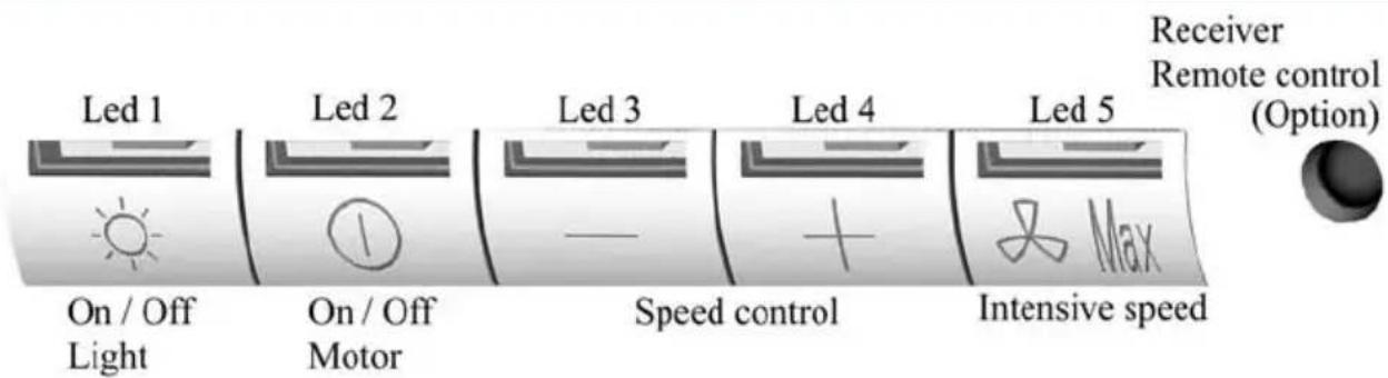
text_image
Led 1 On / Off Light Led 2 On / Off Motor Led 3 Speed control Led 4 Intensive speed Led 5 Receiver Remote control (Option) MaxA - EXTRACTION OR RECYCLING : Your cooker hood is supplied in the extraction mode. To use the cooker hood in the recycling mode re-programme the hood as follows:
Starting in the recycling mode (the contaminated air passes into the hood through the grease filters and the purifying activated charcoal filter and back out into the kitchen through grilles).
Press the ‘+’ button (while the motor and lights are switched ‘OFF’) until the five LED lights will flash twice to indicate confirmation that the cooker hood is in the recycling mode.
Reverting to the extraction mode (The cooker hood is ducted to the outside).
Press the '+' button (while the motor and lights are switched 'OFF') until the five LED lights will flash once to indicate confirmation that the cooker hood is in the extraction mode.
B - BASIC INSTRUCTIONS
Lighting
Press LED button 1 to switch 'ON' the lights and the LED will illuminate to confirm the lights are switched 'ON'.
Motor
Press LED button 2 to switch 'ON' the fan motor (and adjust the speed of the fan motor by pressing the LED button '+' and '-' ) and the LED lights 2, 3 and 4 will illuminate. The fan speed will be increased if constant pressure is kept on the (+) button.
LED 2 : Minimum speed - cooking with one pan or simmering
LED 2 & 3 : Medium speed - normal cooking with up to 4 pans
LED 2, 3 & 4 : Maximum speed - frying and cooking foods with strong odours
Press LED button 5 to obtain the boost position for maximum effect and the LED will illuminate to confirm fan is switched 'ON'.
C - COMPLEMENTARY INSTRUCTIONS
- Boost speed :
To obtain the best performance it is advisable to switch 'ON' the cooker hood a few minutes (in the boost setting) before you start cooking. To program the complementary function, proceed as follows:
- Press LED button 2 to switch 'ON' the fan motor and adjust the speed of the fan by pressing the LED button '+' and '-''. You should keep applying pressure to the '+' and '-' button until the required speed is selected.
- Press LED button 5 (boost speed) to switch 'ON' the fan motor in the boost setting. Press LED button 5 to switch 'OFF' the boost setting immediately.
It is advisable too that you should leave it running in the boost setting for approximately 5 minutes after finishing.
- Pre-set stop of the boost speed :
A pre-set stop after 5 minutes of the boost speed is available.
Your cooker hood is supplied with a deactivated pre-set stop of the boost speed. To use the cooker hood with a pre-set stop of the boost speed re-programme the hood as follows:
The lights and the fan motor should be switched 'OFF' to set the timer.
Push the LED button ‘-’ until the LED lights will flash :
One flash of the LED lights 2,3, and 4 = function is switched 'OFF'.
Two flashes of the LED lights 2,3, and 4 = function is switched 'ON'.
While the 5 minutes timer is running, It is available to stop immediately the boost speed by pressing the led button 5.
While the 5 minutes timer is running, the indication of saturation of the filters is switched 'OFF'.
If a pre-set stop for the hood is switched 'ON' and the 5 minutes timer is still running, the boost speed will be switched 'OFF' together with the pre-set stop for the hood after the count down of 5, 10 or 15 minutes. It is available to stop the boost speed before the count down of the preset stop of the hood by pressing the led button 5.
- Pre-set stop for the hood :
This function allows you to program the cooker hood to automatically stop cooking after a pre-set period. The lights and the fan motor should be switched 'OFF' to set the timer.
Proceed by repeatedly pressing the LED button 5 (Boost speed):
Two flashes of the LED button 1 & 5 = 5 minutes delay.
Three flashes of the LED button 1 & 5 = 10 minutes delay.
Four flashes of the LED button 1 & 5 = 15 minutes delay.
One flash of the LED button indicates the function is switched 'OFF'.
You can switch the cooker hood ‘ON’ and adjust the speed. The LED buttons 2, 3 and 4 will flash to indicate the fan motor is switched ‘ON’ and which speed has been selected.
One flash = stop after 15 minutes.
Two flashes = stop after 10 minutes.
Three flashes = stop after 15 minutes.
- Indication of saturation of the metal grease filters :
After 200 hours use, one quick flash of the LED 1 will indicate that you must clean the metal grease filters. (See chapter on ‘Maintenance’).
To reset the 200 hours timer back to zero requires the motor and lights must be switched 'OFF'; then and proceed as follows:
Press the LED button ‘+’ for 3 to 4 seconds and the LED lights 1,2,3, 4 and 5 will flash to confirm the programme has been reset to zero.
- Indication of saturation of the active charcoal filter :
After 400 hours use, two quick flash of the LED 1 will indicate that you must replace the active charcoal filter and clean the metal grease filters. (See chapter on 'Maintenance').
To reset the 400-hour timer the motor and lights must be switched 'OFF'.
Push the LED button '+' for 10 seconds.
One flash of the LED lights 1,2,3,4 and 5 = function is switched 'OFF'.
Two flashes of the LED lights 1,2,3,4 and 5 = function is switched 'ON'.
Instructions for replacing the active charcoal filter are given in the chapter on 'Recycling'.
• Pre-set remote control handset
Your cooker hood is supplied with a deactivated remote control receiver. To use the cooker hood with a remote control re-programme the hood as follows:
Press the LED button (Lighting) '1' while the motor and lights are switched 'OFF', until the LED lights 1 will flash to confirm the programme has been activated :
One flash of the LED lights 1 = function is switched 'OFF'.
Two flashes of the LED lights 1 = function is switched 'ON'.
Caution, the remote control handset must be fitted with standard LR03-AAA size 1.5V zinc-carbon alkaline batteries as illustrated Fig. 9. These batteries should give a long life and constant discharge throughout their life. These batteries must be disposed of properly and could explode if damaged or exposed to heat.
Do not dispose of on fire. Dispose of batteries in the appropriate sort container to protect the environment.
- Setup Process
Modification: How to adjust the internal microprocessor data to suit the type of motor fitted to this appliance and the supply frequency of 50 or 60 Hz..
1 - Disconnect the cooker hood from the mains supply.
2 - Push the button 0/1 MOTOR.
3 - Reconnect the mains supply while pushing the button 0/1 MOTOR for at least 2 seconds.
4 - Release the button 0/1 MOTOR (the Leds flash for about 3 seconds : capacity's confirmation SETUP PROCESS).
5 - While the LED is flashing select the motor type used while pushing one of the 5 buttons in accordance with the following:
BUTTON 0/1 Light : Motor EBM PRO 220-240 V AC 50 Hz / 220 V AC 60 Hz.
BUTTON 0/1 Motor : Motor FABER 8/28 e 8/50 220-240 V AC 50 Hz / 220 V AC 60 Hz.
BUTTON Speed (-): Motor EBM MISTRAL 220-240 V AC 50 Hz / 220 V AC 60 Hz.
BUTTON Speed (+) : Motor EBM PRO 220-240 V AC 50 Hz / 220 V AC 60 Hz.
BUTTON Intensive speed : Motor FABER K40-K50 220-240 V AC 50 Hz / 220 V AC 60 Hz.
N.B.: If you have not selected a motor type while the LED is flashing the microprocessor will automatically select the default motor EBM PRO 220 - 240 V AC 50 Hz / 220 V AC 60 Hz.
5 USEFUL HINTS
- To obtain the best performance we recommend you to switch 'ON' the cooker hood a few minutes (in the boost setting) before you start cooking and you should leave it running for approximately 15 minutes after finishing.
• IMPORTANT: NEVER DO FLAMBÉ COOKING UNDER THIS COOKER HOOD - Do not leave frying pans unattended during use as over-heated fat and oil might catch fire.
- Do not leave naked flames under this cooker hood.
- Switch 'OFF' the electric and gas before removing pots and pans.
- Ensure heating areas on your hotplate are covered with pots and pans when using the hotplate and cooker hood simultaneously.
6 MAINTENANCE
Before carrying out any maintenance or cleaning isolate the cooker hood from the mains supply.
The cooker hood must be kept clean; a build up of fat or grease may cause a fire hazard.
Casing
- Wipe the cooker hood frequently with a clean cloth, which has been immersed in warm water containing a mild detergent and wrung out.
- Never use excessive amounts of water when cleaning particularly around the control panel.
- Never use scouring pads or abrasive cleaners.
• Always wear protective gloves when cleaning the cooker hood.
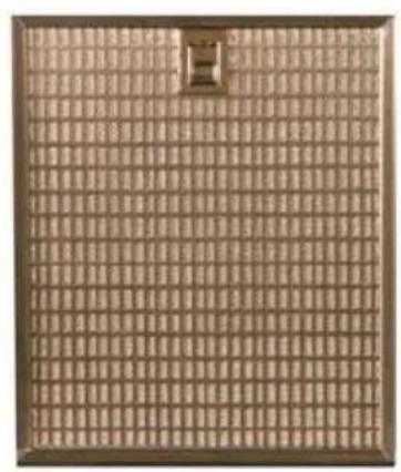
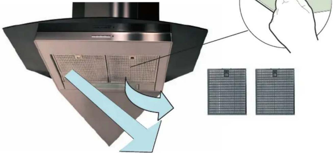
Metal Grease Filters : The metal grease filters absorb grease and dust during cooking in order to keep
clean the cooker hood inside. The grease filters should be cleaned once a month or more frequently if the hood is used for more than 3 hours per day.
To remove and replace the metal grease filters
- Remove the metal grease filters one at a time by releasing the catches on the filters; the filters can now be removed.
- The metal grease filters should be washed, by hand, in mild soapy water or in a dishwasher.
- Allow to dry before replacing.
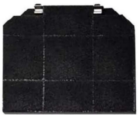
Active Charcoal Filter : The charcoal filter cannot be cleaned. The filter should be replaced at least every three months or more frequently if the hood is used for more than three hours per day.
To remove and replace the filter
- Remove the metal grease filters.
- Press against the two retaining clips, which hold the charcoal filter in place and this will allow the filter to drop down and be removed.
- Clean the surrounding area and metal grease filters as directed above.
- Insert the replacement filter and ensure the two retaining clips are correctly located.
- Replace the metal grease filters.
Extraction tube : Check every 6 months that the dirty air is being extracted correctly. Comply with local rules and regulations with regard to the extraction of ventilated air.
Lighting : If the lamp fails to function check to ensure it is fitted correctly into the holder. If lamp failure has occurred then it should be replaced with identical replacement.
Do not replace with any other type of lamp and do not fit a lamp with a higher rating.
7 GUARANTEE AND AFTER SALES SERVICE
- In the event of any malfunction or anomaly, notify your fitter who will have to check the appliance and its connection.
- In the event of damage to the mains supply cable, this can only be replaced by at approved repair centre appointed by the manufacturer who will have the required tools and equipment to carry out any repairs properly. Repairs carried out by other persons will invalidate the guarantee.
- Use only genuine spare parts. Should these warnings fail to be observed it could affect the safety of your cooker hood.
- When ordering spare parts quote the model number and serial number written on the rating plate, which is found on the casing behind the grease filters inside the hood.
• Proof of purchase will be required when requesting service. Therefore, please have your receipt available when requesting service as this constitutes the date from which your guarantee commenced.
This Guarantee does not cover :
- Damage or calls resulting from transportation, improper use or neglect, the replacement of any light bulbs or filters or removable parts of glass or plastic.
These items are considered to be consumable under the terms of this guarantee.
8 REMARKS
This appliance complies with European regulations on low voltages Directive 2006/95/CE on electrical safety, and with the following European regulations: Directive 2004/108/CE on electromagnetic compatibility and Directive 93/68 on EC marking.
When this crossed-out wheeled bin symbol is attached to a product it means the product is covered by the European directive 2002/96/EC. Your product is designed and manufactured with high quality materials and components, which can be recycled and reused. Please inform yourself about the local separate collection system for electrical and electronic product. Please act according to your local rules and do not dispose of your old products with your normal household waste. The correct disposal of your old product will help prevent potential negative consequences for the environment and human health.
LED 2 = NIVEL MÍNIMO
LED 2 Y 3 = NIVEL INTERMEDIO
LED 2, 3 Y 4 = NIVEL MÁXIMO
3 INSTALLATIE VAN HET APPARAAT
Any permanent electrical installation must comply with the latest I.E.E. Regulations and local Electricity Board regulations. For your own safety this should be undertaken by a qualified electrician e.g. your local Electricity Board, or a contractor who is on the roll of the National Inspection Council for Electrical Installation Contracting (NICEIC).
ELECTRICAL CONNECTION
Before connecting to the mains supply ensure that the mains voltage corresponds to the voltage on the rating plate inside the cooker hood.
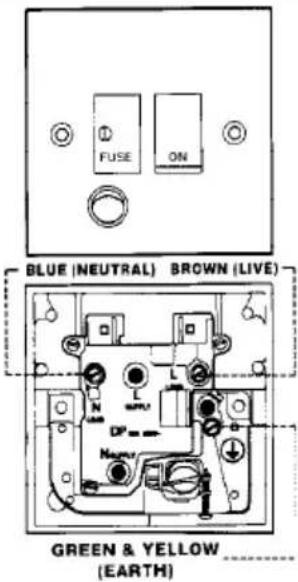
This appliance is fitted with a 2 core mains cable and must be permanently connected to the electricity supply via a double-pole switch having 3mm minimum contact gap on each pole. A Switched Fuse Connection Unit to BS.1363 Part 4, fitted with a 3 Amp fuse, is a recommended mains suppl connection accessory to ensure compliance with the Safety Requirements applicable to fixed wiring instructions.
text_image
FUSE ON BLUE (NEUTRAL) BROWN (LIVE) GREEN & YELLOW (EARTH)The wires in this mains lead are coloured in accordance with the following code:
Green-Yellow Earth Blue Neutral Brown Live
As the colours of the wires in the mains lead of this appliance may not correspond with the coloured markings identifying the terminals in your connection unit, proceed as follows:-
The wire which is coloured blue must be connected to the terminal which is marked with the letter 'N' or coloured black.
The wire which is coloured brown must be connected to the terminal which is marked with the letter 'L' or coloured red.
CH
natural_image
Coiled black electrical cable with two terminal leads (no text or symbols visible)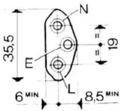
text_image
35,5 E N 19 6 MIN L 8,5 MIN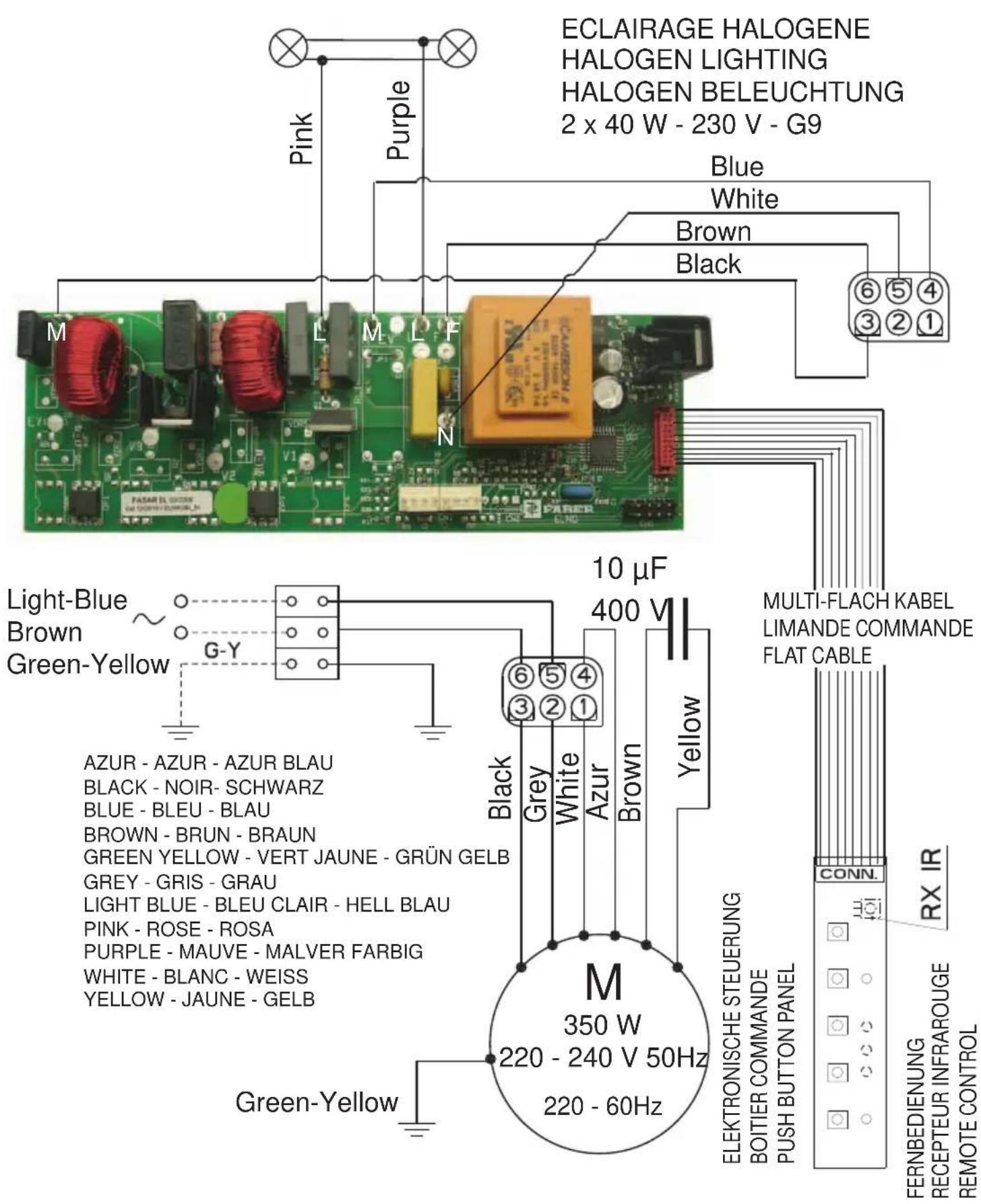
text_image
ECLAIRAGE HALOGENE HALOGEN LIGHTING HALOGEN BELEUCHTUNG 2 x 40 W - 230 V - G9 Pink Purple Blue White Brown Black M L M L F N 6 5 4 ③②① FASAR EL GREEN AMGENTELLOURS 10 µF 400 V Multi-FLACH KABEL LIMANDE COMMANDE FLAT CABLE Light-Blue Brown Green-Yellow G-Y Black Grey White Azur Brown Yellow AZUR - AZUR - AZUR BLAU BLACK - NOIR- SCHWARZ BLUE - BLEU - BLAU BROWN - BRUN - BRAUN GREEN YELLOW - VERT JAUNE - GRÜN GELB GREY - GRIS - GRAU LIGHT BLUE - BLEU CLAIR - HELL BLAU PINK - ROSE - ROSA PURPLE - MAUVE - MALVER FARBIG WHITE - BLANC - WEISS YELLOW - JAUNE - GELB M 350 W 220 - 240 V 50Hz 220 - 60Hz ELEKTRONISCHE STEUERUNG BOITIER COMMANDE PUSH BUTTON PANEL CONN. RX IR FERNBEDIENUNG RECEPTEUR INFRAROUGE REMOTE CONTROL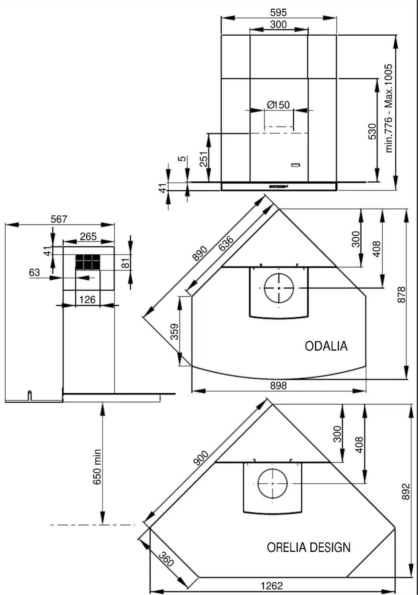
text_image
595 300 Ø150 530 min.776 - Max.1005 5 251 41 567 265 81 63 126 890 636 359 300 408 878 ODALIA 898 650 min 900 300 408 892 360 ORELIA DESIGN 1262Composants Components Bauelemente
Componenti
Componentes
Onderdelen
natural_image
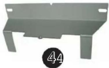
Metal bracket with two side slots and a circular badge showing the number 44 (no text or symbols on the bracket itself)KIT
text_image
Exploded view diagram of a battery pack assembly with exploded view and component labels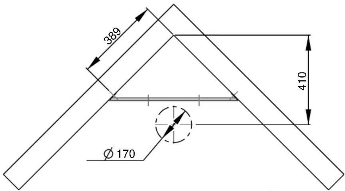
text_image
389 410 Ø 170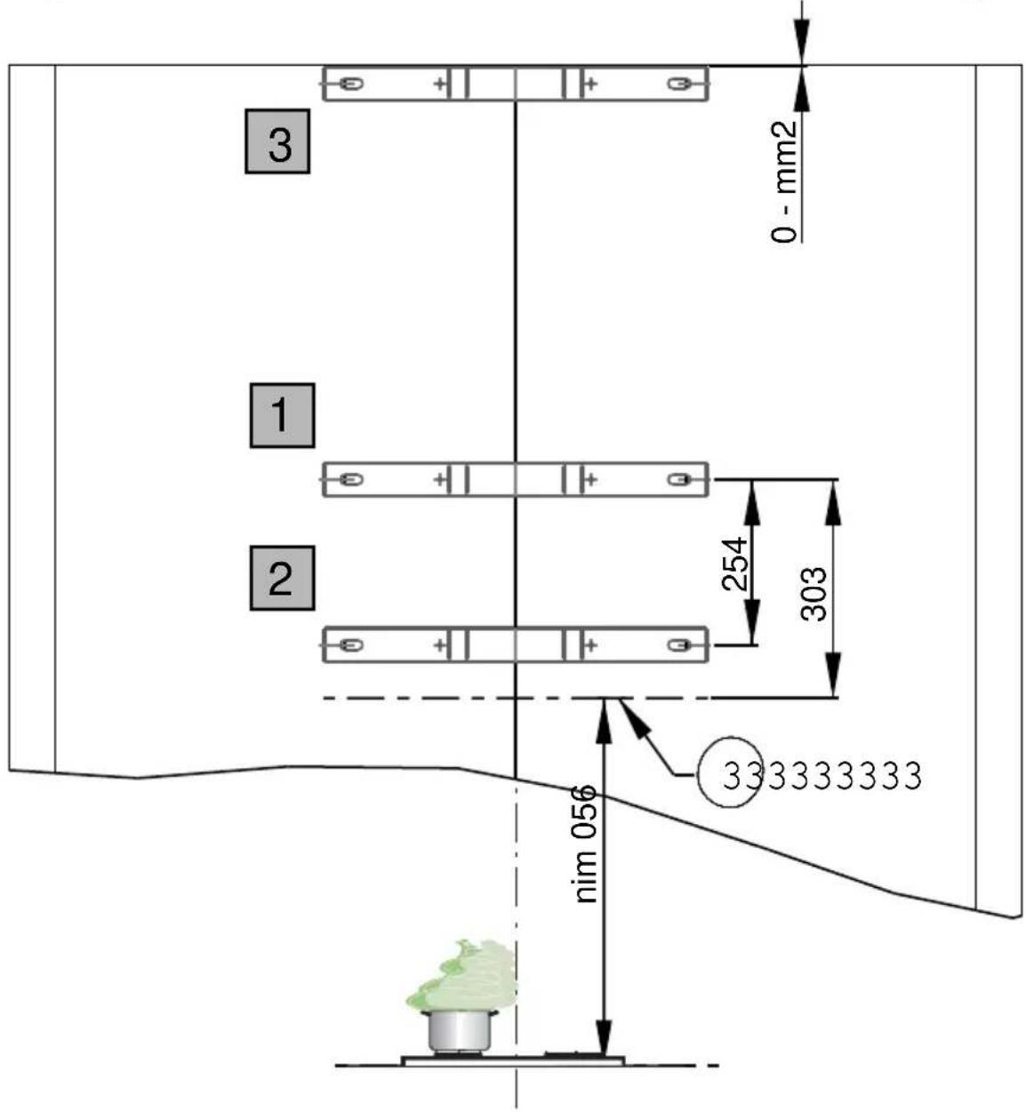
text_image
0 - mm2 1 2 254 303 333333333 nim 056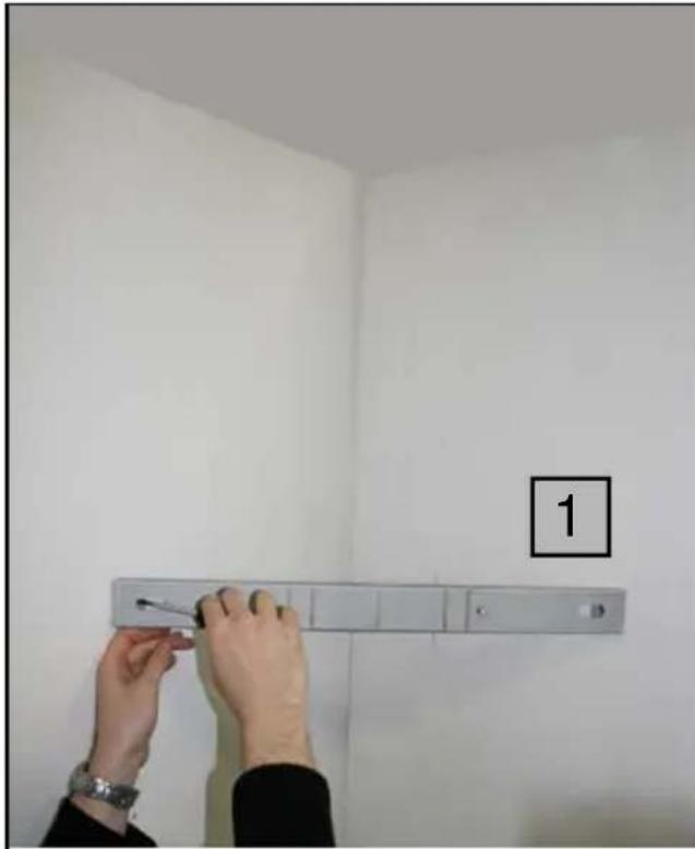
text_image
1
natural_image
Two metallic screw fasteners with threaded end caps, shown from different angles (no text or symbols visible)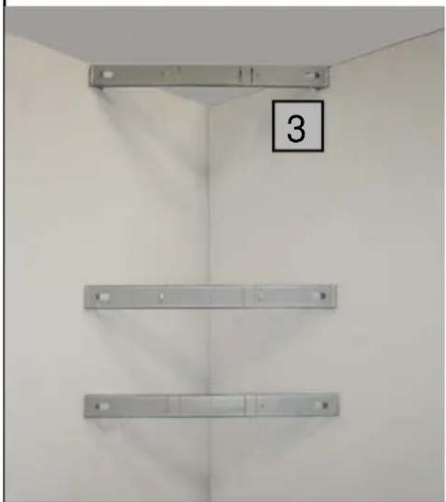
natural_image
Interior wall-mounted air ducts mounted on a wall, no visible text or symbols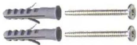
natural_image
Two metallic screw fasteners with threaded end caps, shown from different angles (no text or symbols visible)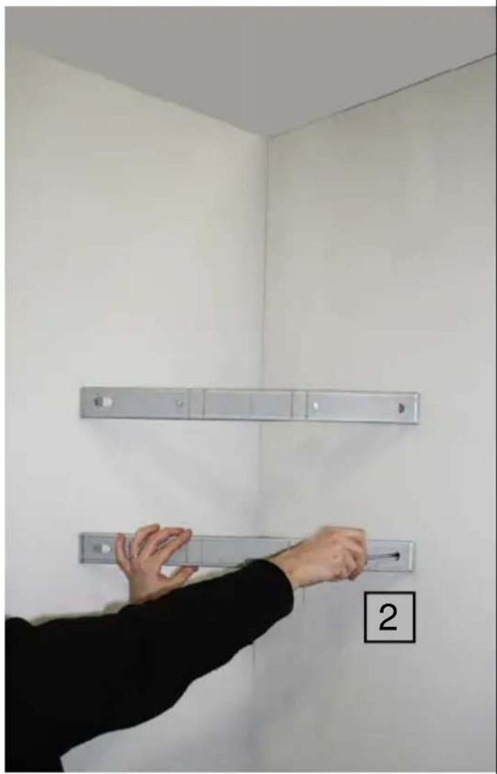
natural_image
Person installing or adjusting a wall-mounted fixture in a room with numbered labels (2), no visible text or symbols on the fixtures or background.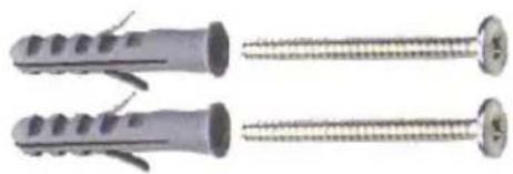
natural_image
Two metallic screw fasteners with threaded end caps, shown from different angles (no text or symbols visible)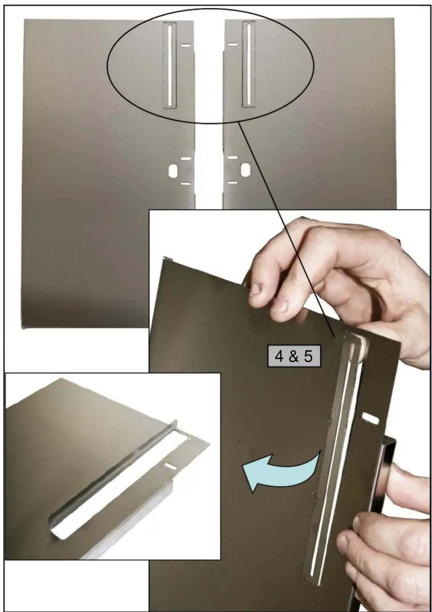
text_image
4 & 5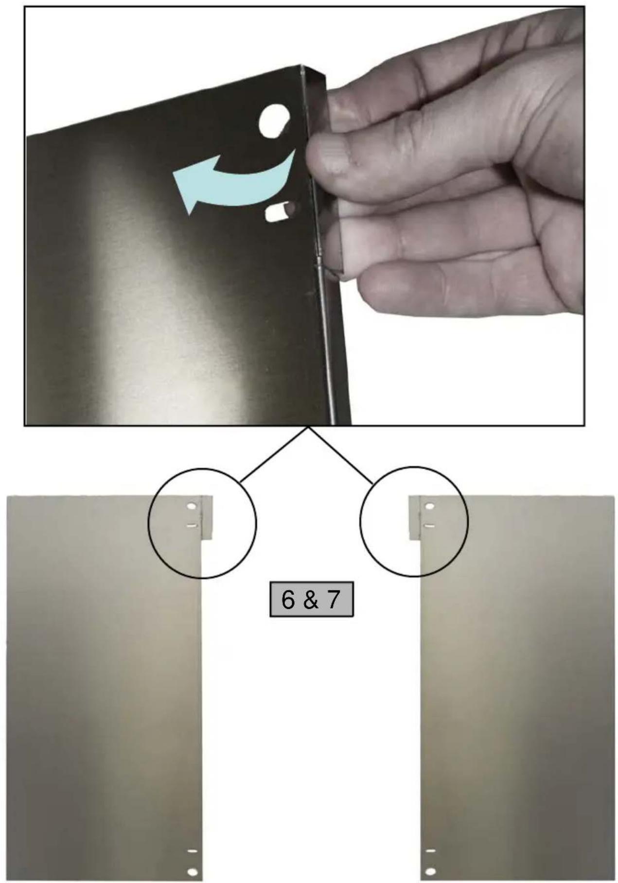
natural_image
Hand placing a rectangular object on top of a metal tray, with a blue arrow pointing to a white strip inside (no text or symbols visible)8 & 9
natural_image
Exterior view of a gray metal enclosure with a vertical slot and mounting feet (no text or symbols visible)
natural_image
Exterior view of a gray metal enclosure with a vertical slot and mounting holes (no text or symbols visible)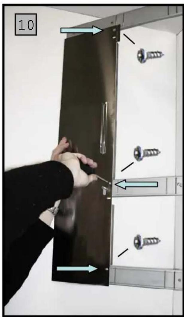
text_image
10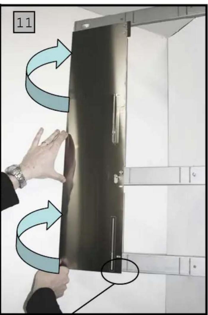
text_image
11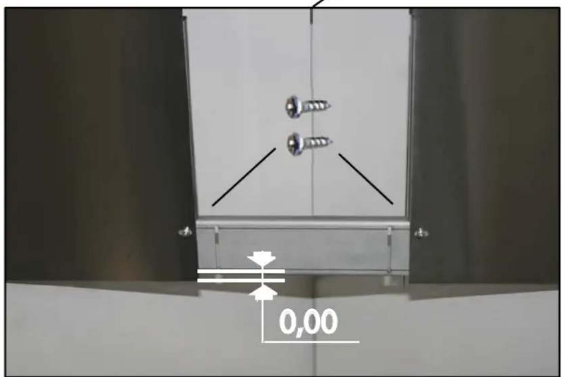
text_image
0,00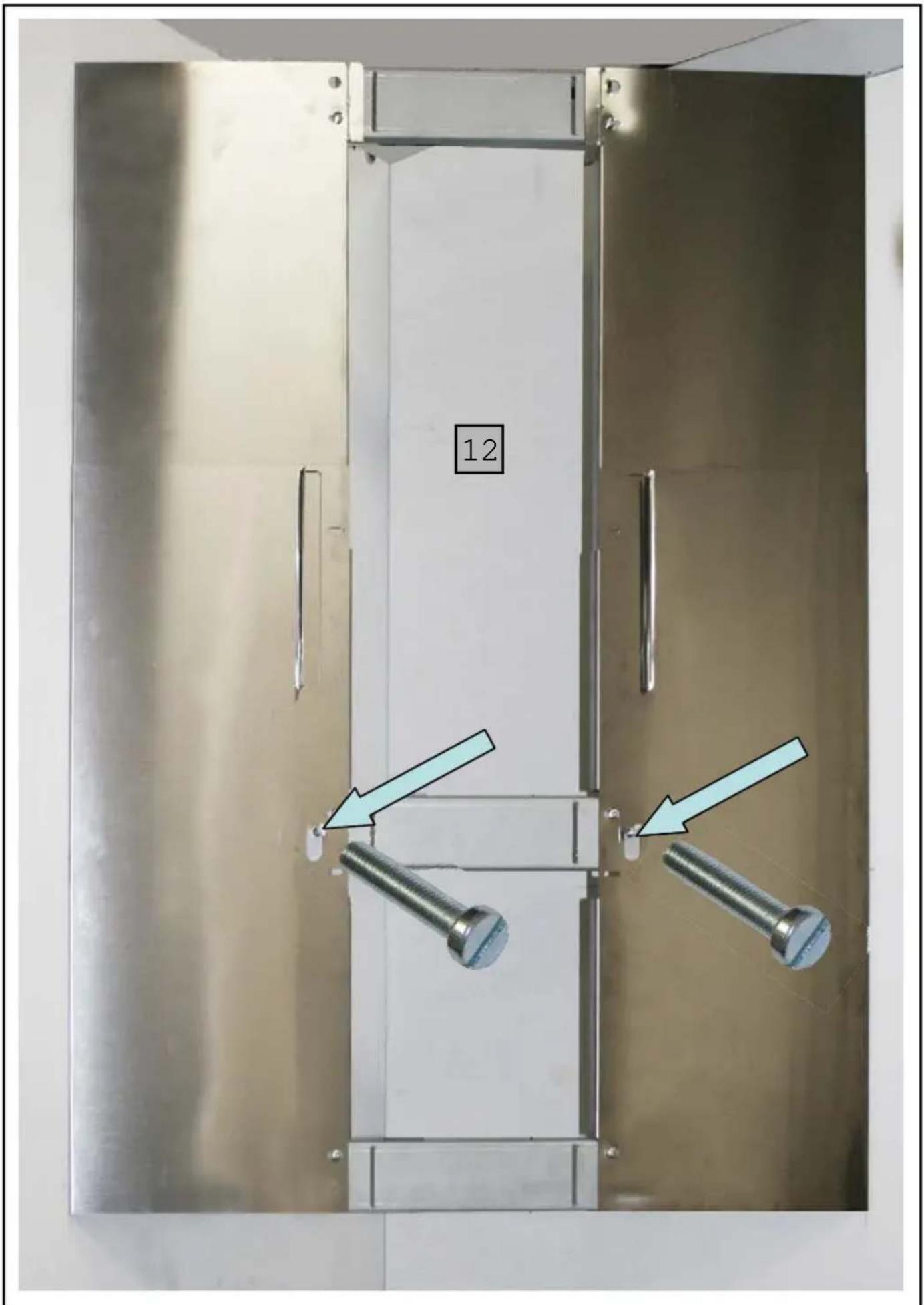
text_image
12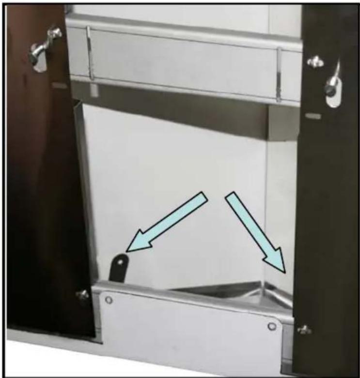
natural_image
Interior view of a stainless steel enclosure with two directional arrows indicating movement or force (no text or symbols present)
natural_image
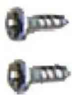
Two metallic screw fasteners with threaded end caps, shown from different angles (no text or symbols visible)13
natural_image
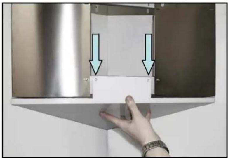
Hand placing a white plastic cabinet with two arrows pointing downward (no text or symbols visible)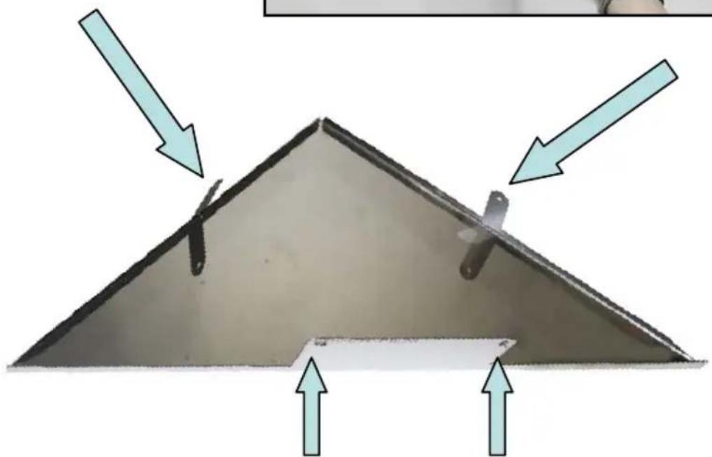
natural_image
Diagram of a triangular structure with arrows indicating direction and a small object inside, no text or symbols present.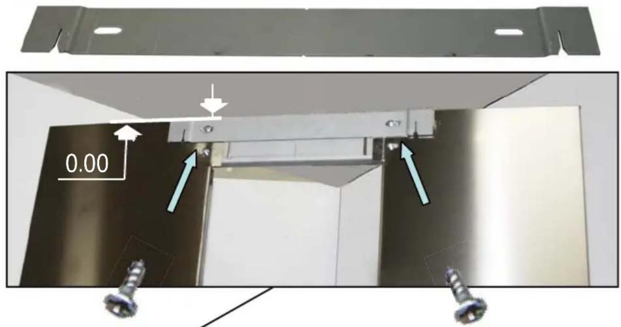
text_image
0.00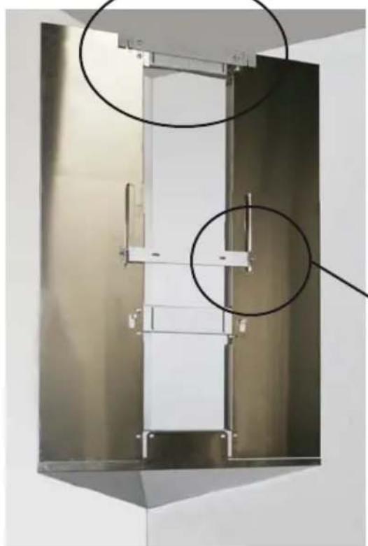
natural_image
Metallic industrial cabinet or enclosure with two circular annotations highlighting internal components (no visible text or symbols)14 & 15
natural_image
Close-up of a metallic mechanical component with a slot and mounting bracket (no visible text or symbols)
natural_image
Metal plate with two recessed slots and a flange, no visible text or symbols16
natural_image
Metal kitchen air conditioner unit with curved arrows indicating rotation or flow, no visible text or symbols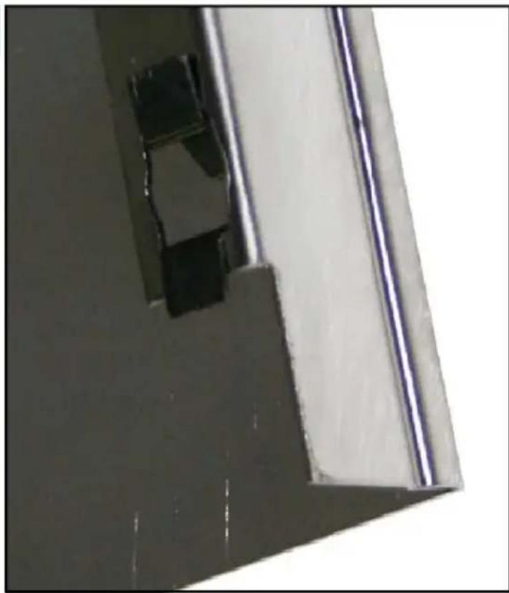
natural_image
Close-up of a metallic panel or bracket with a small black square cutout, no visible text or symbols.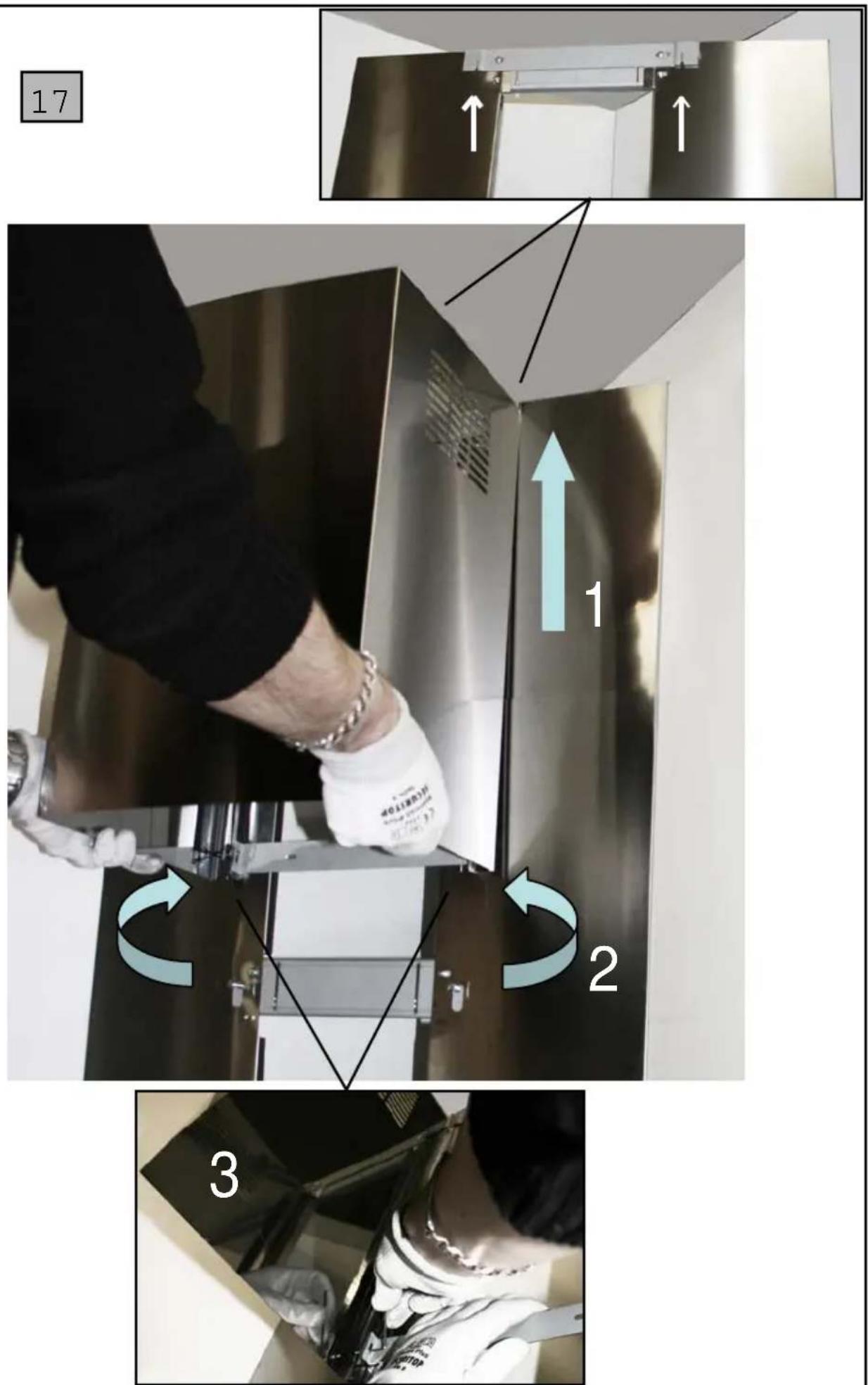
1
text_image
2a 7a 7b 2b 1 6 1 16 305 650 mm min. 5 3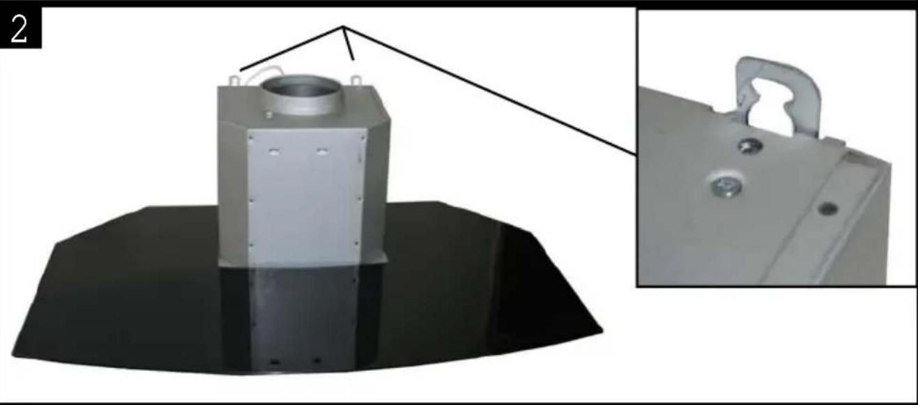
natural_image
Exterior view of a mechanical device with a cylindrical component mounted on a black base, shown with an inset close-up of its side (no text or symbols visible)3
text_image
3a 12a Vr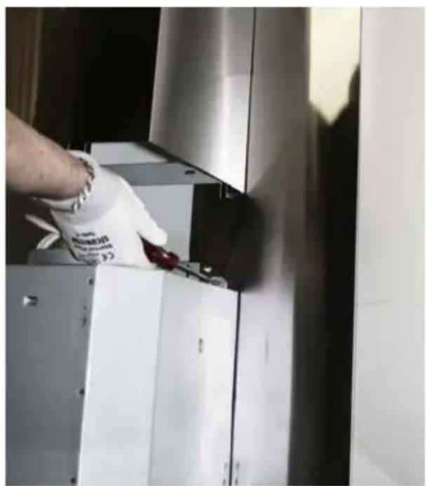
natural_image
Person cleaning a stainless steel kitchen appliance with a cloth (no visible text or symbols)
text_image
Vr Vr3b
6
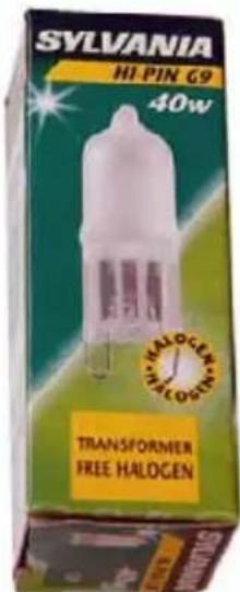
Halogen Beleuchtung Halogen Lighting Eclairage halogène Alogene Luci Alógenas Luz Halogeen Verlichting 2 x 40 W - 230 V
natural_image
Close-up of a stainless steel kitchen chimney with ventilation grilles and airflow arrows (no text or symbols)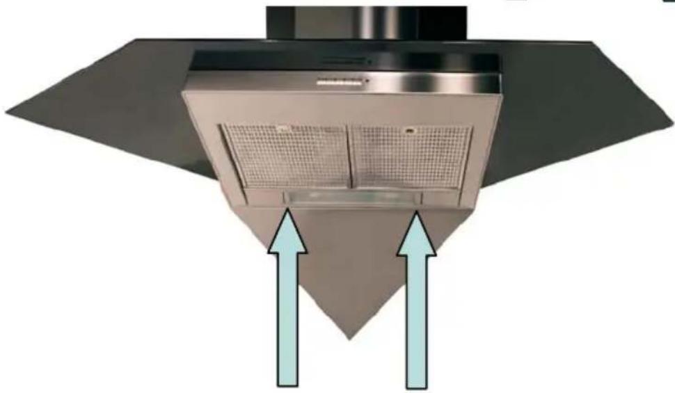
natural_image
Exterior view of a stainless steel kitchen chimney with two upward arrows indicating airflow or ventilation direction (no text or symbols)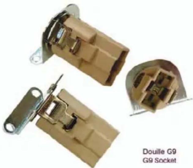
natural_image
Close-up of two beige electrical connector components with metal fittings, labeled 'Douille G9 G9 Socket' (no other text or symbols)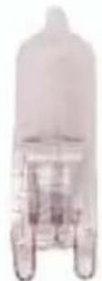
HI - PIN G9
40 W - 230 V
text_image
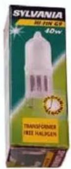
SYLVANIA HI PIN G9 40w HALOGEN HALOGEN TRANSFORMER FREE HALOGEN7
text_image
44 4 G R Ø 150 7a R G8
text_image
Technical diagram showing a mechanical assembly with labeled components and a hand interacting with a component, including a green directional arrow.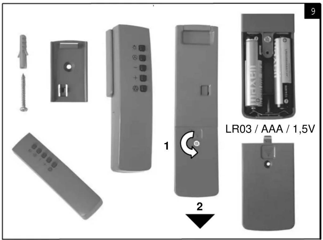
text_image
LR03 / AAA / 1,5VACCESSOIRES ACCESSORIES ZUBEHÖRE
ACCESSORI
ACCESORIA
ACCESSOIRES
text_image
Ancient Chinese text panel with dense vertical columns of classical script, likely from a historical or literary manuscript.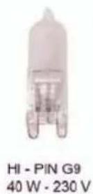
text_image
SYLVANIA HI TIN GR 40W TRANSFORMER FREE HALIGENx 213MC075
natural_image
Black rectangular object with grid pattern and two small white clips at top (no text or symbols)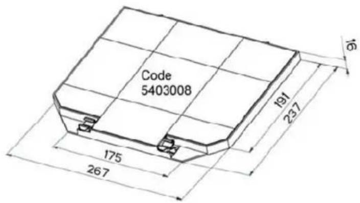
text_image
Code 5403008 191 237 175 267 16Plaque Signalétique de la hotte Rating plate of the cookerhood Typenschild im Inneren der Dunstesse Etichetta all'interno della cappa Etiqueta de la campana Typeplaatje van de afzuigkap
natural_image
Illustration of a kitchen chimney with airflow and grid pattern, showing internal structure and component details (no text or symbols)Modèle Model Modell Modello Modelo Model
text_image
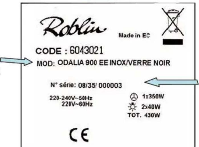
Roblin Made in EC CODE : 6043021 MOD: ODALIA 900 EE INOX/VERRE NOIR N° série: 08/35/ 000003 220-240V~50Hz 220V~60Hz 1x350W 2x40W TOT. 430W CENuméro de série Serial number Seriennummer Numero di serie Numero de serie Serienummer
text_image
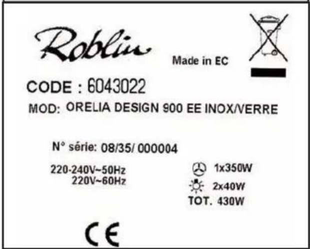
Roblin Made in EC CODE : 6043022 MOD: ORELIA DESIGN 900 EE INOX/VERRE N° série: 08/35/ 000004 220-240V~50Hz 220V~60Hz 1x350W 2x40W TOT. 430W CERoblin
FRANKE France S.A.S.