
GAB85MDS3H - Motherboard GIGABYTE - Free user manual and instructions
Find the device manual for free GAB85MDS3H GIGABYTE in PDF.
| Product Type | Motherboard |
| Brand | Gigabyte |
| Model | GAB85MDS3H |
| CPU Socket | LGA1150 |
| Chipset | Intel B85 Express |
| Form Factor | Micro-ATX |
| Dimensions | 24.4 x 17.4 cm |
| Memory Type | DDR3 1066/1333/1600 MHz non-ECC |
| Number of Memory Slots | 2 x DDR3 DIMM (max 16 GB) |
| Expansion Slots | 1 x PCIe 3.0 x16, 1 x PCIe 2.0 x16, 2 x PCIe 2.0 x1 |
| SATA Connectors | 4 x SATA 3 Gb/s, 2 x SATA 6 Gb/s |
| Onboard USB Connectors | USB 3.0 (2 on rear, 1 header), USB 2.0 (6 on rear, 2 headers) |
| Video Outputs | 1 x D-Sub, 1 x DVI-D |
| Audio | Realtek ALC887, 7.1-channel HD |
| Network | Realtek GbE LAN |
| Power Requirement | ATX 24-pin + 4-pin CPU |
| Operating Temperature | 0°C to 40°C |
| Weight (approx.) | 0.5 kg |
| Warranty | 3 years (depending on retailer) |
| Main Features | Support for 4th Gen Intel Core processors, DualBIOS, high definition audio, USB 3.0, DVI-D and VGA |
| Maintenance & Cleaning | Clean with a dry, lint-free cloth; avoid liquids; discharge static electricity before handling |
| Safety | Disconnect power before any intervention; respect connector polarities; do not touch socket contacts |
| Spare Parts & Repairability | Components are integrated; CMOS battery is replaceable (CR2032). Contact Gigabyte support for any repairs. |
Frequently Asked Questions - GAB85MDS3H GIGABYTE
User questions about GAB85MDS3H GIGABYTE
0 question about this device. Answer the ones you know or ask your own.
Ask a new question about this device
Download the instructions for your Motherboard in PDF format for free! Find your manual GAB85MDS3H - GIGABYTE and take your electronic device back in hand. On this page are published all the documents necessary for the use of your device. GAB85MDS3H by GIGABYTE.
USER MANUAL GAB85MDS3H GIGABYTE
- The sequence of installation may differ depending on the type of case and devices used. The installation instructions below apply to GIGABYTE's desktop systems and are for reference only.
Refer to the user's manual included for detailed motherboard specifications.
Before installing the devices, make sure they are compliant with the connectors on your computer. - Before installing the devices, be sure to turn off the devices and your computer. Unplug the power cord from the power outlet to prevent damage to the devices and the system components.
- Place the computer system on a stable surface to prevent improper installation resulted from shaking.

Installing a CPU and CPU cooler
A. Installing an Intel CPU (skip this step if the motherboard has a built-in CPU)
A-1 Refer to the following instructions based on your CPU specifications:
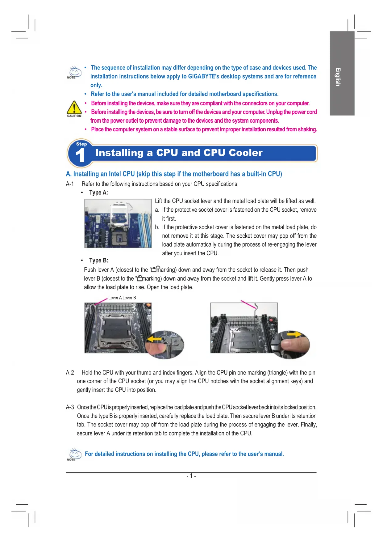
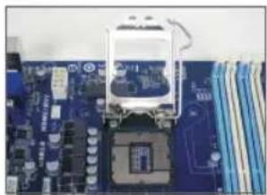
Type A:
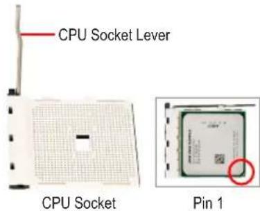
Lift the CPU socket lever and the metal load plate will be lifted as well. a. If the protective socket cover is fastened on the CPU socket, remove it first.
b. If the protective socket cover is fastened on the metal load plate, do not remove it at this stage. The socket cover may pop off from the load plate automatically during the process of re-engaging the lever after you insert the CPU.
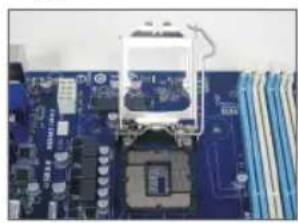
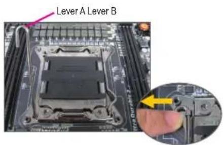
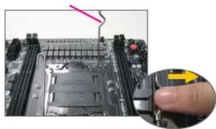
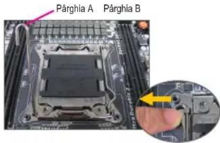
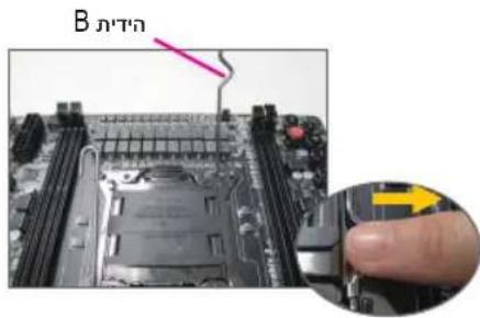
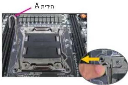
Type B:
Push lever A (closest to the "marking) down and away from the socket to release it. Then push lever B (closest to the "marking) down and away from the socket and lift it. Gently press lever A to allow the load plate to rise. Open the load plate.
A-2 Hold the CPU with your thumb and index fingers. Align the CPU pin one marking (triangle) with the pin one corner of the CPU socket (or you may align the CPU notches with the socket alignment keys) and gently insert the CPU into position.
A-3 Once the CPU is properly inserted, replace the load plate and push the CPU socket lever back into its locked position. Once the type B is properly inserted, carefully replace the load plate. Then secure lever B under its retention tab. The socket cover may pop off from the load plate during the process of engaging the lever. Finally, secure lever A under its retention tab to complete the installation of the CPU.

For detailed instructions on installing the CPU, please refer to the user's manual.
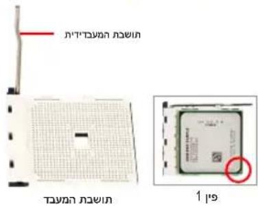
B. Installing an AMD CPU (skip this step if the motherboard has a built-in CPU)
B-1 Completely raise the CPU socket lever. Align the CPU pin one (small triangle marking) with the triangle marking on the CPU socket and gently insert the CPU into the socket. Make sure that the CPU pins fit perfectly into their holes.
B-2 Once the CPU is positioned into its socket, place one finger down on the middle of the CPU, lowering the socket lever and latching it into the fully locked position.

- Do not force the CPU into the CPU socket. The CPU cannot fit in if oriented incorrectly. Adjust the CPU orientation if this occurs.
DO NOT touch socket contacts. To protect the CPU socket, always replace the protective socket cover when the CPU is not installed.
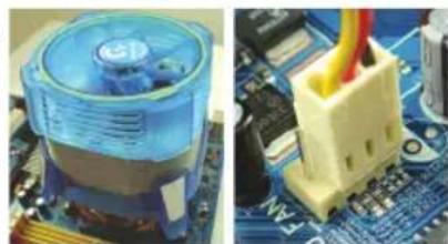
C. Installing the CPU cooler
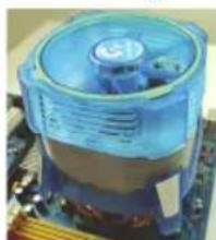
C-1 Before installing the CPU cooler, please first add a thin layer of heat sink paste on the surface of the CPU. Then install the cooler (refer to the installation manual for your CPU cooler).
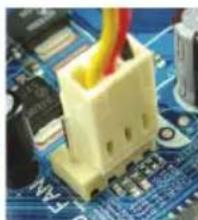
C-2 Connect the CPU cooler cable to the CPU_FAN connector located on the motherboard so that the cooler can properly function to prevent the CPU from overheating.

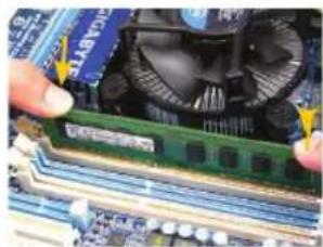
Installing Memory
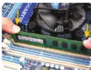
Note the orientation of the memory module. Spread the retaining clips at both ends of the memory socket. Place the memory module on the socket. As indicated in the picture on the left, place your fingers on the top edge of the memory, push down on the memory and insert it vertically into the memory socket. The clips at both ends of the socket will snap into place when the memory module is securely inserted.

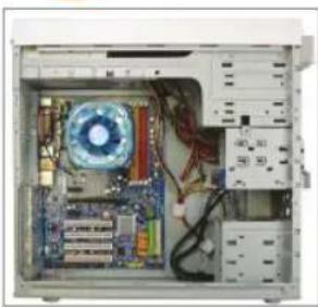
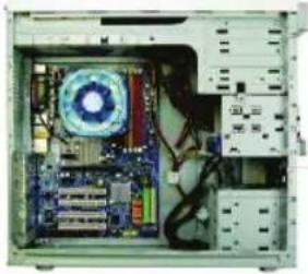
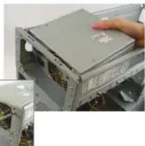
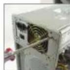
Preparing the Case and Installing a Power Supply

Using the GIGABYTE desktop system as the demonstration example, please first remove both sides and the lid of the case in order to install the power supply. Place the power supply in the correct place in the case and secure it with screws. Installation and placement of the power supply may differ depending on the type of case used.

To ensure sufficient power can be supplied to your system, it is recommended that a power supply of good quality be used. If a power supply is used that does not provide the required power, the result can lead to an unstable or unbootable system.
Step 4
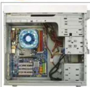
Installing the Motherboard
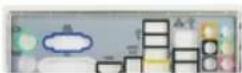
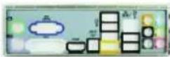
Remove the original I/O shield from the back of the case and replace it with the motherboard I/O shield. Place the motherboard within the case by positioning it into its I/O shield. Align the mounting screw holes on the motherboard with their corresponding mounting holes on the case. Secure the motherboard in place with screws.
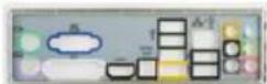
I/O Shield
Step 5
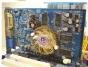
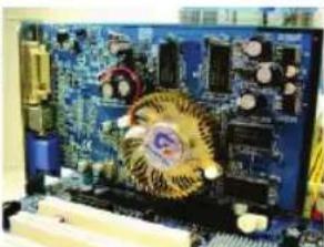
Installing an Expansion Card
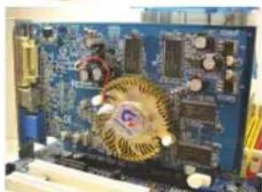
PCI Express Graphics Card
Locate an expansion slot that supports your card and remove the slot cover from the case back panel. Then insert the expansion card into the slot. Secure the expansion card's bracket to the case back panel with a screw.

- Before purchasing an expansion card, check the length of the card, making sure it can fit into your case.
Make sure that the expansion card is fully seated in its slot.
Step 6
Installing IDE and SATA Devices

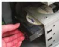
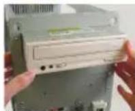
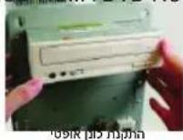
Installing an Optical Drive
6-1 Install your optical drives, such as DVD-ROM and CD-ROM drives.
Remove the 5.25" drive bay cover from the front of the case. Mount the optical drive in the 5.25" drive bay and secure it with screws.
Installing a Hard Drive
6-2 Install your IDE and SATA hard drives.
Install the hard drive into a drive bay within the case and secure it with screws.

- One motherboard IDE connector can connect up to two IDE devices. Prior to installation, check the jumper settings (master and slave) on your IDE devices.
If more than one hard drive is installed, enter system BIOS Setup to set the hard drive boot sequence.
Step 7
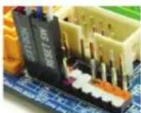
Connecting Cables to Internal Connectors
7-1 Connect cables to internal connectors and headers on the motherboard, including IDE/SATA connectors, and front panel audio, USB, IEEE 1394 headers, etc.
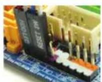
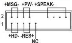
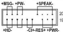
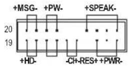
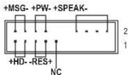
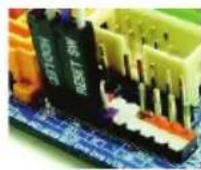
7-2 Attach the front panel module (differs depending on the case design, consisting of power indicator, hard drive activity indicator, speakers, reset switch, power switch, etc.) from the case to the front panel header (F PANEL) on the motherboard.
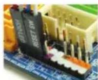
Front Panel Header
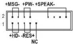
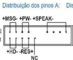
Pin Assignments A:
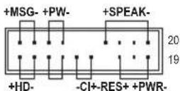
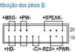
Pin Assignments B:
MSG: Message/Power/Sleep LED
PWR: Power LED
PW: Power Switch
SPEAK:Speaker
HD: Hard Drive Activity LED
RES: Reset Switch
Cl: Chassis Intrusion Header
(Note) The pin assignments for the front panel header may differ by model. Refer to the motherboard user's manual for the actual pin assignments.
Step
8
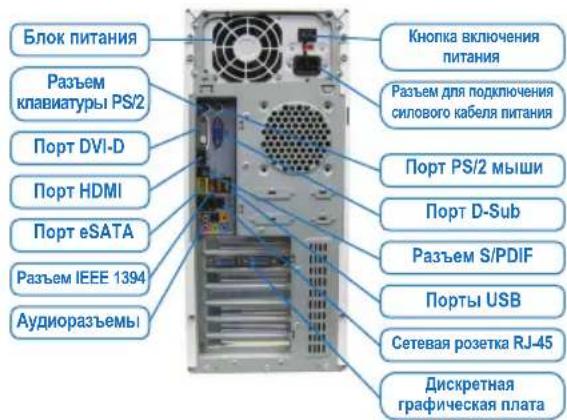
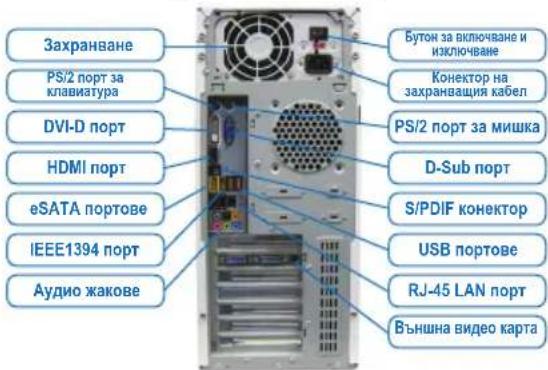
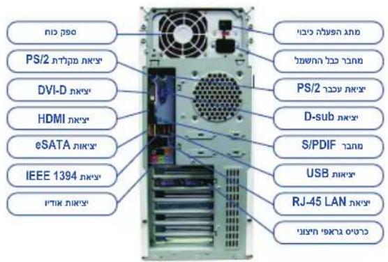
Connecting Peripherals
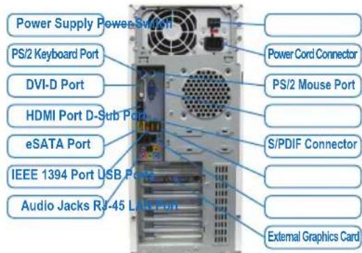
Back Panel of the Case
Once the steps above have been completed, connect the peripheral devices to the computer, such as the keyboard, mouse, monitor, etc. Then connect the power, turn on the system, and install all required software.

Conector do painel frontal
yctahOBka cnCTeMHoN nNaTbI
CHIMNE 3aIpykny pa3bEmOB BBOda/BbIBOda Ha 3aIHe IaHEI KOpnyca
UYCTAHOBITE HA ee MecTO NaHEIb PA3bEMOB BBODA/BbIBOda N3 KOMIIeKTA
NOCTABKN CnCTEMHOI PnATbI. YCTAHOBITE CNCTEMHYO PnATy B KOpnyce,
COBMECTNB pa3bEmbl Ha 3aIHeI NaHEI CNCTEMHOI PnATe C OTBepCTNMI H
NAHEIN BBODA/BbIBOda. COBMECTNE KpeENKHbE OTBepCTN CNCTEMHOI PnATbIC COOTBEcTBYIOUIMN OTBepCTNMI KOpnyca. 3akpeiNTe CNCTEMHYO PnATy B
KOpnyce PI K c nOMoUb BInTOB.
3aŋnyuka pa3bEmOB BBOda/BBBObda
war 5
yctahOBka nlaTbI pacwnpeHn
TpaHneckaPcExpressnata
OnpeDenTe pa3bem pacwnpeHn, coBmecTmbi C yctaHaBnBaEmo nnatoi pacwnpeHn. YdaIte 3arnyk npa3bema Ha 3aHne naHn Kopnyca. YcTaHOBtE pIaTy pacwnpeHn B pa3bem. 3akpenTe nnaHky nIaTbI paunpeHn Ha 3adHe naneHn Kopnyca C nOMOsBu BNHTa.

- Пара д поукьд паы расирени Вьяснite ee ra6apntbI (ДИИНУ) n yбeДNTecb, чTO данhoe устpoичТВО мохно установпь B корпсв Башero ПК.
- y6eHntecb,уTo nIaTa paCunpeHnB OwIa B pa3bEm do ynopa.
war 6
YctahOBka IDE- n SATA-yctpoiCTB
YCTAHOBKA OTNIUChEKOHAKONITEN

YcTaHOBKa JKeCTKOrO DmckA
6-1 YcTaHOBKa ONTnueckoro HakoNtTeRi (DVD-ROM n CD-ROM).
YdaIte 3aRnyuKy 5,25-IOm OTceKa Ha nepeDHe nAHeN KOpNyCa. YcTaHOBnTe ONTWeCKn HAcONITeNb B OTCEK N 3aKpEnITE yCTPOJCTBO BNHTAMN.
6-2 YctaHOBka JecTkoI DE- n SATA-dncka
YctaHOBNTe JecTKn DnCK BOTCEK DnJy JceTkoRTO NsCKA N3akpenTe erO BVHTAMN.

- Odn pa3bem IDE ha cnctemno nnaTe noDepxNbaet Dba IDE-ycTroPcTBA. Ipepd yctahOBKOIDE-ycTroCtB ONpeDeJIte C NOMOuIIO nepembyK COOTBETCTByUoi npexn pa60tbl (master nn slave).
- EcIN Bbl yCTaHOBUN B KOMNbIOTep HeCKOJIbKO JcEeTKNX DnCKOB, BB13OBITE MeHIO HAcTPOEK BIOS Setup n onpeJeNTe JcEeTKNI DnCK, C KOTOPORo 6yET 3arpykaTbCnCTema.

Pokkquenne Ka6e ne K BnytpenHnM pa3bemam
7-1 IopKnIOUHTe INTEPpeChbIe Ka6eN K BHyTpeHHM pa3bEmaM Ha CnCTeMHo nIaTe: IDE/SATA, Audio Na nepeHne NaHeN, USB, IEEE 1394 n T.n.
7-2Поdkноче anemte ha nepeDnei naHEn KOpnyca PIK (KoJIueCTBO np pacnoJoxeHne anemetOB 3aBnCIT OT MOdEiN KOpnyca; obIHyO, Ha nepeDnei naHEn npcCyTCTByOT INdNKaTOP nITaHnRA, INdNKaTOp AKTNBHOCHT NKeCTKOFO DnCKA, DNHAMK KOpnyca, KHONKa Nepe3arpy3KN I KNONKa NITaHnRA) K pa3bemy nepeDnei naHEn (F PANEL)Ha cnCTEmHO nnate.
Pa3bem nepeDne naHen
Pa3MeueHHe KOHTAKTOB; BapnAHT A Pa3MeueHHe KOHTAKTOB; BapnAHT B
MSG: INDnkaTOp coo6eHn/ nHTaHn/OxuDaHn
PWR: INDINKAtop nHTaHn
PW: KhoNka BKnOyehn NtTaHn
SPEAK:ДинамкКорпуca
HD: INHINKATOPAKTNBHOCTW KECTKORO DNCKA
RES: Khonka nepe3atpy3k
Cl: DaTnK BCKpbTnK Kopnyca
(Примочи) PacnoJoxeHne KOHTaKTOB pa3bema nepedHe naneHnI pya3nHybIX moTeNe I nlat MoXeT pa3nUaTbcra. Ha3naHeHne KOHTaKTOB pa3bema F_PANEL npNBedeHO B PyKOBOcCTBe NOJIb3OBAteTn CnCTeMHo IJIaTbl.

PoiKIOueHne nepnOpepnHbIX yCTpOInCTB
PacnoIoxKeHne pa3bEmOB Ha 3aDHe nHaHei
BbnoHnB Cbe nepeucnHbIe DeIcTBn, nOKnIOHTe K KOMNbIoTepy nepupepnHbIe yCTpoCTBa:KnabNAtpy, Mblb, MOHITOp nT.I. IOnKnIOHTe BnIKy CnIOBOrO Ka6eNBA CcTeByUo pO3ETK, BKNIOHTe NK uYctaHOBtE Heo6xOdHMoe nporpamMHOe ObecneueHne.

Push lever A (closest to the "marking) down and away from the socket to release it. Then push lever B (closest to the "marking) down and away from the socket and lift it. Gently press lever A to allow the load plate to rise. Open the load plate.
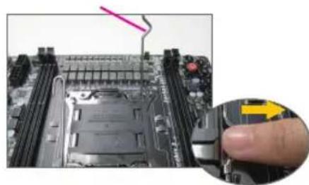
A-2 Hold the CPU with your thumb and index fingers. Align the CPU pin one marking (triangle) with the pin one corner of the CPU socket (or you may align the CPU notches with the socket alignment keys) and gently insert the CPU into position.
CI:KoHEkTOP3aCnHAnu3aun3a
OTBopeHa KyTnA
(3a6eJekka) Ha3Haehnra Ta HnnHOBeTe Ha npeHnnaHe MoRat Da ce pa3NnHuBaT npn pa3NnHuHTE MOnEIn.
BnKTe pBkoBOcTBOTO Ha notpe6nteHa IbHHaTaNtKa 3a BaHnHHe Ha3haueHn.

Cbbp3BaHe Ha Nepnpepn YcTpoiCTBa
3aen naneHn Koprnya
Korato npnKnIOHnTe CbC CTbnKnTe no-rope, CBpbKeTe nepnepnHy yctpoNCTBa c KOMnIObpa, KaTO HApnpMeP,KnabNaTpya, MUska,MOHITOp n dp. Iocne BkIooHete cnCTeMaTa B eJeKtpueeckata Mpexa N INCTaIInpaTe Heo6xOdmnrt CoqTpyep.

PWR: Auxvia LED Aetroupyias
PW: Diakottns tropodociaSPEAK: Hyio
HD: Auxvia LED aieroupyia 0kAnpou bikou
RES: DIAKONTN ES TAVEKKIVNONS
Cl:EuVdEtnpaTnpaiaQouIou
(Enjeiwoj) Oi avotheoeic akidow yia to mtpoovio laiaio evbexetai va diaepouv avaloayo ie ooyteo.
AvatpeETo 0yExpiio xpnTn ts mntpikic yia t cuykeepievec avaotei ackiow.

nW/nnw/nnnLED nW nW:MSG
nW LED nW nW:PWR
nW nW nW:PW
nW nW:SPEAK
nW nW nW LED nW HD
nW nW nW:RES
nW nW nW:CI
B:
A:
Tn
n nnnn nn nnnnnnnnnnnnnnnnnnnnnnnnnnnnnnnnnnnnnnnnnnnnnnnnnnnnnnnnnnnnnnnnnnnnnnnnnnnnnnnnnnnnn
D'97nn D'7nn nn
功
8
n nn nnnn nn nnnn nn nnnn nn nnnn nn nnnn nn nnnn nn nnnn nn nnnn nn nnnn nn nnnn nn nnnn nn nnnn nn nnnn nn nnnn nn nnnn nn nnnn nn nnnn nn nnnn nn nnnn nn nnnn nn nnnn nn nnnn nn nnnn nn nnnn nn nnnn nn nannn nn nnnn nn nnnn nn nnnn nn nnnn nn
TANN NNNN
Dn n
4
nniin nnnn nn nnnn (I/O shield) nnnnnn nnnn nnnn nnnn nnnn nnnn nnnn nnnn nnnn nnnn nnnn nnnn nnnn nnnn nnnn nnnn nnnn nnnn nnnn nnnn nnnn nnnn nnnn nnnn nnnn nnnn nnnn nnnn nnnn nnnn nnnn nnnn nnnn nnnn nannn nnnn nnnn nnnn nnnn nnnn nnnn nnnn nnnn nnnn nnnn nnnn nnnn nnnn nnnn nnnn nnnn nnnn nnnn nnnn nnnn nnnn nnnn nnnn nnnn nnnn nnnn nnnn
(I/O shield)
nann oovnn
5
n nn nnnnnnnnnnnnnnnnnnnnnnnnnnnnnnnnnnnnnnnnnnnnnnnnnnnnnnnnnnnnnnnnnnnnnnnnnnnnnnnnnnnnnnnnnnnnnnnnnnnnnnnnnnnnnnnnnnn
KIN KIT KIT OUTON W IN NK PTT,NNN OY
nienenrnn
yannnnn nn nnnn nn nnnn nn

PCI Express
SATA-IDE nnnn
6
6-1.CD-ROM-DVD-ROM
n 5,25- n 10n
.SATA-IDE 62
nnnnnnnnnnnnnnnnnnnnnnnnnnnnnnnnnnnnnnnnnnnnnnnnnnnnnnnnnnnnnnnnnnnnnnnnnnnnnnn

nnpnn
IDE- n (Jumper) (slave-master)

NOTE
(nnnn nn nnnn nn nnnn nn nnnn nn nnnn nn
Tn 1-2
Tn Tn nnn nn nn nn nn nn nn nn nn nn nn nn nn nn nn nn nn nn nn nn nn nn nn nn nn nn nn nn nn nn nn nn nn nn nn nn nn nn nn nn nn nn nn nn nn nn nn nn nn nn nn nn nn nn nn nn nn nn nn nn nn nn nn nn nn nn nn nn nn nn nn nn nn nn nn nn nn nn nn nn nn nn nn nn nn nn nn nn nn nn nn nn nn nn nn nn nn nn.
un,ynnnn nnynnnn nnnnnnnnnnnnnnnnnnnnnnnnnnnnnnnnnnnnnnnnnnnnnnnnnnnnnnnnnnnnnnnnnnnnnnnnnnnnnnnnnnnnnnnnnnnnnnnnnnnnnnn
nnn nnnn nn nnnn nnnn nnnn nnnn nnnn nnnn nnnn nnnn nnnn nnnn nnnn nnnn nnnn nnnn nnnn nnnn nnnn nnnn nnnn nnnn nnnn nnnn nnnn nnnn nnnn nnnn nnnn nnnn nnnn nnnn nnnn nnnn nnnn nnnn

Tynnn npnnn .
y nnnn nn nnnn nn nnnn nn nnnn nn nnnn nn nnnn nn nnnn nn nnnn nn nnnn nn nnnn nn nnnn nn nnnn nn nnnn nn nnnn nn nnnn nn nnnn nn nnnn nn nnnn nn nnnn nn nnnn nn nnnn nn nnnn nn nnnn nn nnnn nn nnnn nn nnnn
1-
H

n nn nnnn nn nn nn nn nn nn nn nn nn nn nn nn nn nn nn nn nn nn nn nn nn nn nn nn nn nn nn nn nn nn nn nn nn nn nn nn nn nn nn nn nn nn nn nn nn nn nn nn nn nn nn nn nn nn nn nn nn nn nn nn nn nn nn nn nn nn nn nn nn nn nn nn nn nn nn nn nn nn nn nn nn nn nn nn nn nn nn nn nn nn nn nn nn nn nn nn nn nn nn nn
nD 90 nnnn nn

GIGABYTE Wnwnnnn nn nnnn nn nnnnnnnnnnnnnnnnnnnnnnnnnnnnnnnnnnnnnnnnnnnnnnnnnnnnnnnnnnnnnnnnnnnnnnnnnnnnnnnnnnnnnnnnnnnnnnnnnnnnnnn
peoennnneynnnn no neeepn nnnnnae nnnoe eannn

nnpnn nnnn nn nnnn nnnn nnnn nnnn nnnn nnnn nnnn
GIGABYTE
n nn nnnn nn nnnn nn nnnn nn nnnn nn nnnn
- 1
prn nn nnn npnn nn nn nnn nnnnnnnnnnnnnnnnnnnnnnn
nannnnnn
n nn nnnnnnnnnnnnnnnnnnnnnnnnnnnnnnn
TAYAN TAYAN
1
(nnnn nn nnnn nn) Intel nnnnnnnnn.
1
A 10
n nn nnnnnnnnnnnnnnnnnnnnnnnnnnnnnnnnnnnnnnnnnnnnnnnnnnnnnnnnnnnnnnnnnnnnnnnnnnnnnnnnnnnnnnnnnnnnnnnnnnnnnnnnnnnnnnnnnnnnnnnnnnnnnnnnnnnnnnnnnnnnnnnnnnnnnnnnnnn
:Bao
Bn n n n n nn nnnnnnnnnnnnnnnnnnnnnnnnnnnnnnnnnnnnnnnnnnnnnnnnnnnnnnnnnnnnnnnnnnnnnnnnnnnnnnnnnnnnnnnnnnnnnnnnnnnnnnnnnnnnnnnnnnnnnnnnnnnnnnnnnnnn nn n nn n nn n nn n nn n nn n nn n nn n nn n nn n nn n nn n nn n nn n nn n nn n nn n nn n nn n nn n nn n nn n nn n nn n nn n nn n nn n nn n nn n nn n nn n nn n nn n nn n nn n nn n nn n nn n nn n nn n nn n nn n nn n nn n nn n nn n nn n nn n nn n nn
n nn nnnnnnnnnnnnnnnnnnnnnnnnnnnnnnnnnnnnnnnnnnnnnnnnnnnnnnnnnnnnnnnnnnnnnnnnnnnnnnnnnnnnnnnnnnnnnnnnnnnnnnnnnnnnnnnnnnnnnnnnnnnnnnnnnnnnnnnnnnnnnnn
2-
ynnn nn nnnnnnnnnnnnnnnnnnnnnnnnnnnnnnnnnnnnnnnnnnnnnnnnnnnnnnnnnnnnnnnnnnnnnnnnnnnnnnnnnnnnnnnnnnnnnnnnnnnnnnnnnnnnnnnnnnnnnnn
Tnna nna
wnnnn nn nnnnnnnnnnnnnnnnnnnnnnnnnnnnnnnnnnnnnnnnnnnnnnnnnnnnnnnnnnnnnnnnnnnnnnnnnnnnnnnnnnnnnnnnnnnnnnnnnnnnnnnnnnnnn

- Installing a CPU and CPU cooler
- Installing an Intel CPU (skip this step if the motherboard has a built-in CPU)
- Installing an AMD CPU (skip this step if the motherboard has a built-in CPU)
- Installing the CPU cooler
- O Installing Memory
- Preparing the Case and Installing a Power Supply
- Step 4
- Installing the Motherboard
- Step 5
- Installing an Expansion Card
- Step 6
- Installing IDE and SATA Devices
- Step 7
- Connecting Cables to Internal Connectors
- Step
- 8
- Connecting Peripherals
- yctahOBka cnCTeMHoN nNaTbI
- war 5
- yctahOBka nlaTbI pacwnpeHn
- war 6
- YctahOBka IDE- n SATA-yctpoiCTB
- Pokkquenne Ka6e ne K BnytpenHnM pa3bemam
- PoiKIOueHne nepnOpepnHbIX yCTpOInCTB
- PacnoIoxKeHne pa3bEmOB Ha 3aDHe nHaHei
- Cbbp3BaHe Ha Nepnpepn YcTpoiCTBa
- D'97nn D'7nn nn
- Dn n
- 4
- nann oovnn
- 5
- SATA-IDE nnnn
- 6
- (nnnn nn nnnn nn nnnn nn nnnn nn nnnn nn
- Tynnn npnnn .
- 1-
- H
- nD 90 nnnn nn
- TAYAN TAYAN
- 1
- (nnnn nn nnnn nn) Intel nnnnnnnnn.
Brand : GIGABYTE
Model : GAB85MDS3H
Category : Motherboard