
PlasmaSync 42XP10 - Television NEC - Free user manual and instructions
Find the device manual for free PlasmaSync 42XP10 NEC in PDF.
| Product Type | Plasma Screen Television |
| Brand | NEC |
| Model | PlasmaSync 42XP10 |
| Screen Size | 42 inches (107 cm) diagonal |
| Native Resolution | 1024 x 768 pixels (XGA) |
| Power Supply | 100-240 V AC, 50/60 Hz |
| Power Consumption | Approx. 300 W (typical) |
| Weight | Approx. 32 kg (without stand) |
| Dimensions (W x H x D) | Approx. 1020 x 640 x 115 mm (without stand) |
| Video Inputs | VGA (D-Sub 15), DVI, 2x Composite, S-Video, 2x Component (DVD/HD), RGBHV (BNC) |
| Audio Inputs | 3x Stereo Audio (RCA) |
| Outputs | External control RS-232C (D-Sub 9), External speakers (8W + 8W, 8 ohms) |
| Remote Control | With AA batteries, range 7 m, angle 30°, ID function to control up to 26 monitors |
| Image Functions | Image modes (Standard, Vivid, Cinema 1/2, Default), size adjustment, digital zoom, PIP/PAP, pointer |
| Mounting | VESA 400 x 400 mm (compatible), wall or ceiling mount with appropriate bracket |
| Ventilation | Free space of at least 50 mm around the monitor; monthly cleaning of ventilation grilles |
| Screen Maintenance | Soft, dry cloth; do not use abrasive or alcohol-based products |
| Safety | Automatic shutdown in case of fault; main power switch with protective cover |
| Supplied Accessories | Remote control, batteries, power cord, manual CD-ROM, quick start guide, cable ties |
Frequently Asked Questions - PlasmaSync 42XP10 NEC
User questions about PlasmaSync 42XP10 NEC
0 question about this device. Answer the ones you know or ask your own.
Ask a new question about this device
Download the instructions for your Television in PDF format for free! Find your manual PlasmaSync 42XP10 - NEC and take your electronic device back in hand. On this page are published all the documents necessary for the use of your device. PlasmaSync 42XP10 by NEC.
USER MANUAL PlasmaSync 42XP10 NEC
- Plasma Monitor
- Remote control and AA Batteries
- Power cord
- Users Manual (CD-ROM)
- Start Up Guide (Paper / CD-ROM)
- Main Power Switch cover and screw
- Cable clamps
Table of Contents
Important Safety Instructions. English-1
Important Information. English-2
Safety Precautions and Maintenance. English-3
Recommended Use English-4
Installation
Using Optional Stands/Mounts. English-6
Mounting Location. English-6
Mounting on Ceiling. English-7
Maintenance, Orientation, Cable Management . English-7
Using the Remote. English-8
Part Names and Functions
Control Panel. English-9
Terminal Panel. English-10
Remote Control Functions.. English-11
Power, Display, Digital Zoom, Pointer, Main Power Switch Cover English-12
Remote Control ID. English-13
On-Screen Display (OSD)
Using the OSD. English-14
OSD. English-15
Troubleshooting. English-19
Specifications
P42XP10 English-20
P50XP10 English-21
P60XP10. English-22
Supported Resolutions
P42XP10 English-23
P50XP10 English-25
P60XP10. English-27
Pin Assignment. English-29
Read Before Operating Equipment.
- Read these instructions.
- Keep these instructions.
- Heed all warnings.
- Follow all instructions.
- Do not use this apparatus near water.
- Clean only with a dry cloth.
- Do not block any of the ventilation openings. Install in accordance with the manufacturer's instructions.
- Do not install near any heat sources such as radiators, heat registers, stoves, or other apparatus (including amplifiers) that produce heat.
- Do not defeat the safety purpose of the polarized or grounding-type plug. A polarized plug has two blades with one wider than the other. A grounding type plug has two blades and third grounding prong The wide blade or third prong are provided for your safety. If the provided plug does not fit into your outlet, consult an electrician for replacement of the obsolete outlet.
- Protect the power cord from being walked on or pinched particularly at plugs, convenience receptacles, and the point where they exit from the apparatus.
- Only use attachments/accessories specified by the manufacturer
- Use only with the cart, stand, tripod, bracket, or table specified by the manufacturer, or sold with the apparatus. When a cart is used, use caution when moving the cart or apparatus combination to avoid injury from tip-over.

- Unplug this apparatus during lightning storms or when unused for long periods of time
- Refer all servicing to qualified service personnel. Servicing is required when the apparatus has been damaged in any way, such as when the power-supply cord or plug is damaged, liquid has been spilled or objects have fallen into the apparatus, the apparatus has been exposed to rain or moisture, does not operate normally, or has been dropped
Additional Safety Information
- Th is product may contain lead. Disposal of these materials may be regulated due to environmental considerations.
For disposal or recycling information, please contact your local authorities or the Electronic Industries Alliance: www.eiae.org.
- Damage Requiring Service -The appliance should be serviced by qualified service personnel when:
A. The power supply cord or the plug has been damaged; or
B. Objects have fallen, or liquid has been spilled into the appliance; or
C. The appliance has been exposed to rain; or
D. The appliance does not appear to operate normally or exhibits a marked change in performance; or
E. The appliance has been dropped, or the enclosure damaged.
- Tilt/Stability - All monitors must comply with recommended international global safety standards for tilt and stability properties of its cabinet design.
Do not compromise these design standards by applying excessive pull force to the front, or top, of the cabinet which could ultimately overturn the product.
Also, do not endanger yourself, or children, by placing electronic equipment/toys on the top of the cabinet. Such items could unsuspectingly fall from the top of the set and cause product damage and/or personal injury.
- Wall/Ceiling Mounting - The appliance should be mounted to a wall/ceiling only as recommended by the manufacturer.
- Power Lines - An outdoor antenna should be located away from power lines.
- Outdoor Antenna Grounding - If an outside antenna is connected to the receiver, be sure the antenna system is grounded so as to provide some protection against voltage surges and built up static charges.
Section 810 of the National Electric code. ANSI/NFPA
No.70-1984, provides information with respect to proper grounding of the mats and supporting structure, grounding of the lead-in wire to an antenna-discharge unit, size of grounding connectors, location of antenna discharge unit, connection to grounding electrodes and requirements for the grounding electrode.
- Objects and Liquid Entry - Care should be taken so that objects do not fall and liquids are not spilled into the enclosure through openings.
Apparatus shall not be exposed to dripping or splashing and no objects fllled with liquids, such as vases, shall be placed on apparatus
WARNING
To reduce the risk of fire or electric shock, do not expose this apparatus to rain or moisture.
WARNING

TO PREVENT FIRE OR SHOCK HAZARDS, DO NOT EXPOSE THIS UNIT TO RAIN OR MOISTURE. DO NOT USE THIS UNIT'S POLARIZED PLUG WITH AN EXTENSION CORD RECEPTACLE OR OTHER OUTLETS UNLESS THE PRONGS CAN BE FULLY INSERTED.

REFRAIN FROM OPENING THE CABINET AS THERE ARE HIGH VOLTAGE COMPONENTS INSIDE. REFER SERVICING TO QUALIFIED SERVICE PERSONNEL.
CAUTION
CAUTION: TO REDUCE THE RISK OF ELECTRIC SHOCK, MAKE SURE POWER CORD IS UNPLUGGED FROM WALL SOCKET. TO FULLY DISENGAGE THE POWER TO THE UNIT, PLEASE DISCONNECT THE POWER CORDFROM THE AC OUTLET. DO NOT REMOVE COVER (OR BACK). NO USER SERVICEABLE PARTS INSIDEREFER SERVICING TO QUALIFIED SERVICE PERSONNEL.

This symbol warns user that uninsulated voltage within the unit may have sufficient magnitude to cause electric shock.
Therefore, it is dangerous to make any kind of contact with any part inside this unit.

This symbol alerts the user that important literature concerning the operation and maintenance of this unit has been included. Therefore, it should be read carefully in order to avoid any problems.
CAUTION: Please use the power cord provided with this display in accordance with the table below. If a power cord is not supplied with this equipment, please contact your supplier. For all other cases, please use a power cord that matches the AC voltage of the power outlet and has been approved by and complies with the safety standard of your particular country.
| Plug Type | North America | European Continental | U.K. | Chinese | Japanese |
| Plug Shape | |||||
| Country | U.S.A./Canada | EU (except U.K.) | U.K. | China | Japan |
| Voltage | 120* | 230 | 230 | 220 | 100 |
*When operating the PlasmaSync monitor with its AC 125-240V power supply, use a power supply cord that matches the power supply voltage of the AC power outlet being used.
Canadian Department of
Communications Compliance Statement
DOC: Th is Class B digital apparatus meets all requirements of the Canadian Interference-Causing Equipment Regulations.
C-UL: Bears the C-UL. Mark and is in compliance with Canadian Safety Regulations according to CAN/CSA C22.2 No.60950-1.
FCC Information
- Use the attached specified cables with the P426Y0(P42XP10), P506Y1(P50XP10), or P606Y2(P60XP10) color monitor so as not to interfere with radio and television reception.
(1) Please use the supplied power cord or equivalent to ensure FCC compliance.
(2) Please use shielded video signal cable, 15-pin mini D-SUB to 15-pin mini D-SUB with ferrite cores on both ends (not included).
2. Th is equipment has been tested and found to comply with the limits for a Class B digital device, pursuant to part 15 of the FCC Rules. Th ese limits are designed to provide reasonable protection against harmful interference in a residential installation. This equipment generates, uses, and can radiate radio frequency energy, and, if not installed and used
in accordance with the instructions, may cause harmful interference to radio communications. However, there is no guarantee that interference will not occur in a particular installation. If this equipment does cause harmful interference to radio or television reception, which can be determined by turning the equipment off and on, the user is encouraged to try to correct the interference by one or more of the following measures:
Reorient or relocate the receiving antenna.
- Increase the distance between the equipment and receiver.
- Connect the equipment into an outlet on a circuit different from that to which the receiver is connected.
- Consult your dealer or an experienced radio/TV technician for help.
If necessary, the user should contact the dealer or an experienced radio/ television technician for additional suggestions. The user may find the following booklet, prepared by the Federal Communications Commission, helpful: "How to Identify and Resolve Radio-TV Interference Problems." This booklet is available from the U.S. Government Printing Office, Washington, D.C., 20402, Stock No. 004-000-00345-4.
WARNING
This product equipped with a three-wire grounding (earthed) plug - a plug that has a third (grounding) pin. This plug only fits a grounding-type power outlet. If you are unable to insert the plug into an outlet, contact a licensed electrician to replace the outlet with a properly grounded one. Do not defeat the safety purpose of the grounding plug.
Safety Precautions and Maintenance
Safety Precautions and Maintenance
FOR OPTIMUM PERFORMANCE, PLEASE NOTE THE FOLLOWING WHEN SETTING UP AND USING THE MONITOR:
The plasma display's panel is made up of fine picture elements (cells), of which more than 99.99 percent are active cells. Some cells may not produce light or remain constantly lit. For safe operation and to avoid damaging the unit, read carefully and observe the following instructions.
DO NOT OPEN THE MONITOR. There are no user-serviceable parts inside and opening or removing covers may expose you to dangerous shock hazards or other risks. The manufacturer is not liable for any bodily harm or damage caused if unqualified persons attempt service or open the back cover. Refer all servicing to qualified service personnel.
- Do not spill any liquids into the cabinet or use your monitor near water.
- Do not insert objects of any kind into the cabinet slots, as they may touch dangerous voltage points, which can be harmful or fatal or may cause electric shock, fire or equipment failure.
- Do not bend, crimp or otherwise damage the power cord.
- Do not place any heavy objects on the power cord.
- Damage to the cord may cause shock or fire.
- Do not place this product on a sloping or unstable cart, stand or table, as the monitor may fall, causing serious damage to the monitor.
- Do not use in a moving vehicle, as the unit could drop or topple over and cause injuries.
- The power cable connector is the primary means of detaching the system from the power supply. The monitor should be installed close to a power outlet that is easily accessible.
- Th is equipment shall be connected to a MAIN outlet with a protective earth-ground connection. Do not place any objects onto the monitor and do not use the monitor outdoors.
- Do not use this unit's polarized plug with an extension cord or with outlets unless the prongs can be inserted fully.
- The power supply cord you use must have been approved by and comply with the safety standards of your country. (Type H05VV-F 3G 1mm^2 should be used in Europe)
- In UK, use a BS-approved power cord with molded plug having a black (13A) fuse installed for use with this monitor.
- Use only with 100V to 240V50Hz / 60Hz AC power supply. Continued operation at line voltages greater than 100V to 240V AC will shorten the life of the unit, and might even cause a fire hazard.
- Unplug the power cord during electrical storms or when the unit will not be in use for a long period.
- Do not use monitor in high temperature, humid, dusty, or oily areas.
- Do not cover vent on monitor.
- Clean plasma ventilation areas using a vacuum cleaner with a soft brush nozzle attachment.
- To ensure proper ventilation, cleaning the ventilation areas must be carried out monthly. More frequent cleaning may be necessary depending on the environment in which the plasma monitor is installed.
- Allow adequate ventilation around the monitor so that heat can properly dissipate. Do not block ventilated openings or place the monitor near a radiator or other heat sources. Do not put anything on top of monitor.
- Handle with care when transporting. Save packaging for transporting.
- As is the case with any phosphor-based display (like a CRT monitor, for example) light output will gradually decrease over the life of a Plasma Display Panel.
- To avoid sulfurization it is strongly recommended not to place the unit in a dressing room in a public bath or hot spring bath.

Immediately unplug your monitor from the wall outlet and refer servicing to qualified service personnel under the following conditions:
- When the power supply cord or plug is damaged.
- If liquid has been spilled on, or objects have fallen into the monitor.
- If the monitor has been exposed to rain or water.
- If the monitor has been dropped or the cabinet damaged.
- If the monitor does not operate normally by following operating instructions.
CAUTION
CORRECT PLACEMENT AND ADJUSTMENT OF THE MONITOR CAN REDUCE EYE, SHOULDER AND NECK FATIGUE. CHECK THE FOLLOWING WHEN POSITIONING THE MONITOR:
- For optimum performance, allow 20 minutes for warm-up.
- Rest your eyes periodically by focusing on an object at least 5 feet away. Blink oft en.
- Position the monitor at a 90 degree angle to windows and other light sources to minimize glare and reflections.
- Clean the monitor surface with a lint-free, nonabrasive cloth. Avoid using any cleaning solution or glass cleaner.
- Adjust the monitor's brightness and contrast controls to enhance readability.
- Get regular eye checkups.
Ergonomics
To realize the maximum ergonomic benefits, we recommend the following:
- Use the preset Size and Position controls with standard signals.
- Use the preset Color Setting.
- Do not use primary color blue on a dark background, as it is difficult to see and may produce eye fatigue due to insufficient contrast.
- Th is equipment is not for use at video display work station according to Bildscharb V.
For more detailed information on setting up a healthy work environment, refer to the following document:
American National Standard for Human Factors Engineering of Visual Display Terminal Workstations ANSI-HFS Standard No. 100-1988
Published by:
The Human Factors and Ergonomics Society P.O.Box 1369, Santa Monica, California 90406.
Cleaning the Panel
- When the panel becomes dusty or dirty, wipe gently with soft cloth.
- Do not rub the panel with coarse material.
- Do not apply pressure to the surface.
- Do not use OA cleaner. OA cleaner will cause deterioration or discolor the surface.
Cleaning the Cabinet
- Unplug the power supply.
- Gently wipe the cabinet with a soft cloth.
- To clean the cabinet, dampen the cloth with a neutral detergent and water, wipe the cabinet and follow with a dry cloth.
NOTE: The surface of the cabinet is composed of many types of plastic.
DO NOT clean with benzene thinner, alkaline detergent, alcoholic system detergent, glass cleaner, wax, polish cleaner, soap powder, or insecticide. Rubber or vinyl should not be in contact with the cabinet for an extended period of time. The est types of fluids and materials can cause the paint to deteriorate, crack or peel.
CLEANING THE VENT HOLES
- Clean plasma ventilation areas using a vacuum cleaner with a soft brush nozzle attachment.
- To ensure proper ventilation, cleaning the ventilation areas must be carried out monthly. More frequent cleaning may be necessary depending on the environment in which the plasma monitor is installed.
To avoid or minimize image retention:
Like all phosphor-based display devices and all other gas plasma displays, plasma monitors can be susceptible to image retention under certain circumstances. Certain operating conditions, such as the continuous display of a static image over a prolonged period of time, can result in image retention if proper precautions are not taken. To protect your investment in this plasma monitor, please adhere to the following guidelines and recommendations for minimizing the occurrence of image retention:
- Always enable and use your computer's screen saver function during use with a computer input source.
- Display a moving image whenever possible.
- Change the position of the menu display from time to time.
- Always power down the monitor when you are finished using it.
To reduce the likelihood of image retention from long-term use:
- Lower the Brightness and Contrast levels as much as possible without impairing image readability.
- Display an image with many colors and color gradations (i.e. photographic or photo-realistic images).
- Create image content with minimal contrast between light and dark areas. Use complementary or pastel colors whenever possible.
- Avoid displaying images with few colors and distinct, sharply defined borders between colors.
Plasma monitor driving sound
- The panel of the Plasma monitor is composed of extremely fine pixels and these pixels emit light according to received video signals. This principle may cause you to hear a buzz or electrical hum coming from the Plasma monitor. Also note that the rotation speed of the cooling fan motor increases when the ambient temperature of the Plasma monitor becomes high. You may hear the sound of the motor at that time.
NOTE: The following items are not covered by the warranty.
- Image retention
- Panel generated sound. Examples: Fan motor and electrical noises circuit humming /glass panel buzzing.
OPERATING ENVIRONMENT
Operating environment temperature and humidity: 0^ to +40^ (+32^ to +104^) ; less than 80% RH (cooling vents not blocked) Do not install this unit in a poorly ventilated area, or in locations exposed to high humidity or direct sunlight (or strong artificial light)
WARNING
Not for use in a computer room as defi ned in the Standard for the Protection of Electronic Computer/Data Processing Equipment ANSI/NFPA 75.
NOTE: Please use shielded video signal cable, 15-pin mini D-SUB to 15-pin mini D-SUB with ferrite cores on both ends (not included).
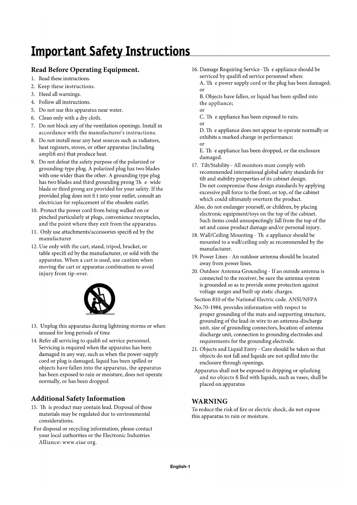
Using Optional Stand/Mounts
An optional stand or mounting apparatus can be installed.
When stand or mounting apparatus is to be installed while the unit is face-down (Figure 1), be sure to lay the protective sheet (the foam sheet that the unit was wrapped in) underneath the unit on order to prevent damage to the screen.
Th is unit must be used with a stand or some type of mounting apparatus. Th is unit is not designed for use without additional support.
- For correct Installation and Mounting it is recommended to use a trained, authorized dealer.
- Failure to follow correct mounting procedures could result in damage to the unit or to the installer.
Product warranty does not cover damage caused by improper installation.
CAUTION:
- To install, follow those instructions included with the stand or mounting apparatus. Use only those devices recommended by the manufacturer.
- Make sure to install stand or mounting apparatus to the unit while on a surface that is strong and stable enough to support the weight of the unit, such as a floor or sturdy table.
- Use the specified clasps for installation.
Take necessary steps to prevent the unit from tipping or falling.
Mounting Location
The ceiling and wall must be strong enough to support the monitor and mounting accessories.
DO NOT install in locations where a door or gate can hit the unit.
DO NOT install in areas where the unit will be subjected to strong vibrations and dust.
DO NOT install near where the main power supply enters the building.
DO NOT install in where people can easily grab and hang onto the unit or the mounting apparatus.
- When mounting in an enclosure or in a recessed area, as in a wall, leave at least 2 inches (50mm) of space between the monitor and the wall for proper ventilation (Figure 2).
- Allow adequate ventilation or provide air conditioning around the monitor, so that heat can properly dissipate away from the unit and mounting apparatus.
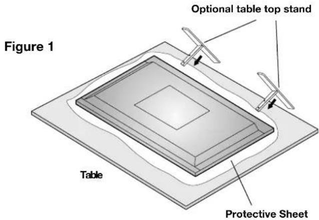
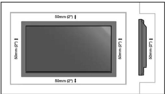
Figure 2
Mounting on Ceiling
- Ensure that the ceiling is sturdy enough to support the weight of the unit and the mounting apparatus over time, against earthquakes, unexpected vibrations, and other external forces.
- Be sure the unit is mounted to a solid structure within the ceiling, such as a support beam. Secure the monitor using bolts, spring lock washers, washer and nut.
DO NOT mount to areas that have no supporting internal structure. DO NOT use wood screws or anchor screws for mounting. DO NOT mount the unit to trim or to hanging fixtures.
Maintenance
Periodically check for loose screws, gaps, distortions, or other problems that may occur with the mounting apparatus. If a problem is detected, please refer to qualified personnel for service.
Regularly check the mounting location for signs of damage or weakness that may occur over time.
Please note the following when mounting on wall or ceiling.
-
When using mounting accessories other than those that are NEC approved, they must comply with the VESA-compatible (FDMlv1) mounting method.
-
NEC strongly recommends using size M8 screws (16mm + thickness of bracket in length). If using screws longer than 16mm, check the depth of the hole. (Recommended Fasten Force: 1125 - 1375N·cm) NEC recommends mounting interfaces that comply with UL1678 standard in North America.
Orientation
When using the display in the portrait position, the monitor should be rotated clockwise so that the left side is moved to the top and the LED indicator light is on the bottom. This will allow for proper ventilation and will extend the lifetime of the monitor. Improper ventilation may shorten the lifetime of the monitor.
When using the display in the portrait position, please turn the Cooling Fan "ON" in the OPTION2 OSD menu.

Cable Management
To conveniently manage cables, use the cable clamps provided to bundle the power cord together with the signal and audio cables at the back of the display.
To attach cable clamps:
- Attach the cable clamps to the display. Insert the anchor of the clamp into the hole on the back of the display. There are 4 cable clamps and 4 clamp holes on the unit.
- After the cable clamp is positioned on the display, wrap the end around the cables. Place the end of the clamp into the slot near the anchor. Pull until cables are snug.
Clamps are designed to stay in place. Once in position, they will be difficult to remove.
3. Cables can be routed to the right or left of the clamp. Use the beaded bands to secure the cables together along their length. Make sure the cables are fully supported.
To detach clamps:
Using pliers, twist the clamp 90 degrees and pull outward. It is possible that the clamp can weaken over time and removing it may cause damage to the clamp.
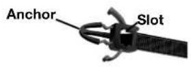

Holes for Clamp anchors

Using the Remote:
Install the remote control batteries.
The remote control is powered by AA batteries. To install or replace batteries:
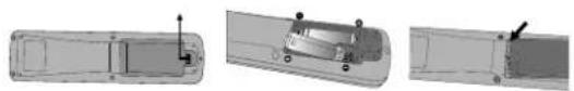
A. Press and slide to open the cover.
B. Align the batteries according to the (+) and (-) indications inside the case.
C. Replace the cover.
CAUTION: Incorrect usage of batteries can result in leaks or bursting. NEC recommends the following battery use:
- Place "AA" size batteries matching the (+) and (-) signs on each battery to the (+) and (-) signs of the battery compartment.
- Do not mix battery brands.
- Do not combine new and old batteries, or mix brands.
Th is can shorten battery life or cause liquid leakage of batteries. - Remove dead batteries immediately to prevent battery acid from leaking into the battery compartment.
- Do not touch exposed battery acid, it may injure skin.
- Do not drop or mishandle the remote.
- Do not get the remote control wet. If the remote does get wet, wipe dry immediately.
- Avoid excessive heat and humidity.
- Do not dispose of batteries in fi re.
- Please follow government regulations or public environmental rules that apply in your country/area when disposing of used batteries.
- When replacing, use only conventional nonrechargeable alkaline or manganese batteries.
- There is a risk of explosion if batteries are replaced incorrectly.
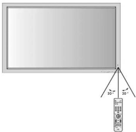
Operating Range for the Remote Control
Point the top of the remote control toward the monitor's remote sensor while pressing buttons. The remote control can be used from the front of the monitor at a maximum distance of 7m / 23 ft. from the front of the Plasma monitor's remote control sensor. The maximum horizontal and vertical angle for use of the remote is 30 degree within a distance of 3.5m / 11.5 ft.
CAUTION
The remote control may not function when direct sunlight or strong illumination strikes the remote control sensor of the Plasma monitor, or when there is an object in the path of the sensor.
Handling the Remote Control
Do not open the remote control other than to install batteries. Do not allow water or other liquid to splash onto the remote control. If the remote control gets wet, wipe it dry immediately.
Avoid exposure to heat and steam.
NOTE: If you do not intend to use the Remote Control for a long period of time, remove the batteries.
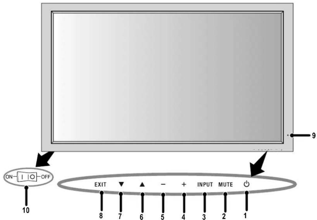
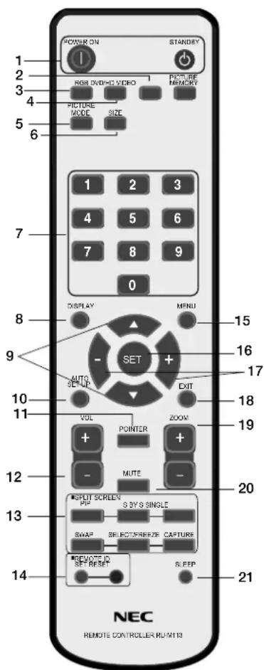
Control Panel
1) POWER
Switches the power on/standby.
2) MUTE
Switches the audio mute ON/OFF.
3) INPUT
Switches between input sources.
Acts as SET button within the OSD menu.
4) PLUS (+)
Increases the setting adjustment within OSD menu.
5) MINUS (-)
Decreases the setting adjustment within OSD menu.
6) UP
Increases the volume level when the OSD is off.
Moves area up to select which setting to is to be adjusted within OSD menu.
7) DOWN
Decreases the volume level when the OSD is off.
Moves down to select which setting is to be adjusted within OSD menu.
8) EXIT
Activates the OSD menu when the OSD menu is off. Exits from the current menu being displayed to the previous menu within the OSD.
9) Remote control sensor and Power indicator
Receives the signal when using the wireless remote control. Glows green when the monitor is active. Glows red when the monitor is in Standby mode. Glows Amber when the monitor is in POWER SAVE mode.
A red blinking Power indicator means that the monitor has detected a failure. Contact qualifi ed personnel in case of failure.
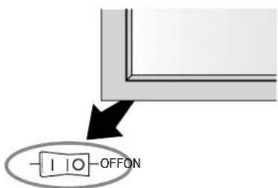
10) Main Power Switch
Seesaw switch to turn the main power on/off.
| Mode Status | indicator light |
| Power On Green | |
| Standby Red | |
| Power save Amber | |
| Diagnosis (Detecting failure) | Red blinking |
NOTE: The POWER button does not completely turn off the display. Use the Main Power Switch to completely turn off the display.
Terminal Panel
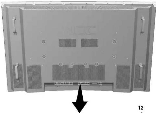
1) EXTERNAL CONTROL OUT (D-Sub 9 pin)
Connect RS-232C output to a second monitor.
2) EXTERNAL CONTROL (D-Sub 9 pin)
Connect RS-232C input to external equipment such as a PC in order to control RS-232C functions.
3) DVI
Input digital RGB signals from a computer or HDTV device having a digital RGB output.
4) AUDIO3
Input the audio signal from external equipment such as a computer, VCR or DVD player.
5) VGA (Mini D-Sub 15 pin)
Analog computer input or output. For proper operation select "D-SUB INPUT" in the OPTION1 OSD menu.
6) RGBHV/DVD/HD2
RGBHV: Input RGB signals from RGB equipment. A Sync-on-Green signal can be connected using the G connector.
DVD/HD2: Connect equipment such as a DVD player, HDTV device, or set-top box. This input can be used with an RGB or component source. For proper operation select "BNC INPUT" in the OPTION1 OSD menu.
7) AUDIO2
Input the audio signal from external equipment such as a computer, VCR or DVD player.
8) DVD/HD1
Connect equipment such as a DVD player, HDTV device, or set-top box.
9) AUDIO1
Input the audio signal from external equipment such as a computer, VCR or DVD player.
10) S-VIDEO in
Input S-video.
11)VIDEO1
Composite video input or output.
12)VIDEO2
Composite video input.
13) EXTERNAL SPEAKER (L and R) connector
Connects to optional speakers. Output the audio signal from AUDIO 1, 2, and 3 to external speakers. NOTE: Speaker Terminal is for 8W + 8W (8 ohm).
14) AC IN
Connects with the supplied power cord.
Information:
For Y/Cb/Cr connections, use the DVD/HD1 or DVD/HD2 terminals.
For SCART connections there are 3 ways to connect:
SCART1: Connect R/G/B to the DVD/HD2 terminals and composite sync. to the HD terminal.
SCART2: Connect R/G/B to the DVD/HD2 terminals and composite sync. to the VIDEO1 terminal.
SCART3: Connect R/G/B + composite sync. to the VGA terminal.
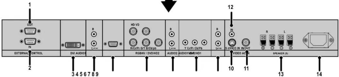
Remote Control Functions
1) POWER ON/STANDBY
Switches the power on/standby.
*If the Power Indicator on the display is not glowing, then no controls will work.
2)VIDEO
Switches the input signal to the VIDEO source.
3) RGB
Switches the input signal to the RGB source.
4) DVD/HD
Switches the input signal to the DVD/HD source.
5) PICTURE MODE
Selects Picture Mode: [STANDARD], [BRIGHT], [CINEMA1], [CINEMA2], [DEFAULT].
STANDARD: for viewing in a bright room
BRIGHT: brighter picture than STANDARD
CINEMA1, 2: for viewing in a dark room, good for movies
DEFAULT: factory default settings
6) SIZE
Set the aspect ratio of the image.
7) KEYPAD
Set REMOTE ID.
8) DISPLAY
Turn on/off the Information OSD.
9) ▲▼
Move selection up or down
10) AUTO SETUP
Adjusts the CLOCK PHASE, CLOCK, and POSITION settings automatically. (Analog RGB signal input only)
11)POINTER
Turn on/off the pointer.
12)VOLUME
Increases/Decreases sound level.
13)SPLITSCREEN
PIP: Picture-in-Picture mode.
S BY S: Side-by-side mode.
SINGLE: Returns to normal mode.
SWAP: Swaps the Split Screen images.
When the QUICK SWAP function (see OSD OPTION4) is ON, SWAP can be used to change signal input. (Single screen mode)
SELECT/FREEZE: Selects which input is active when in split screen mode.
When the PIC FREEZE function (see OSD Option4) is operating, SELECT/FREEZE can be used to display still pictures on the sub screen.
CAPTURE:Captures still picture.
14)REMOTEID
Activates REMOTE ID function.
15) MENU
Turns ON/OFF menu mode.
16)SET
Makes selection.
17)-,+
Increases or decreases amount of adjustment.
18)EXIT
Goes to the previous menu.
19)ZOOM
Enlarges or reduces the picture.
20)MUTE
Mutes audio output.
21)SLEEP
Sleep timer.
NOTE: Any buttons without a corresponding explanation will not work with the Plasmasync display.
Part Names and Functions -continued
POWER
To turn the unit ON and OFF:
- Plug the power cord into an AC outlet.
- Press the Power button (on the unit).
The monitor's ON/STANDBY indicator turns red and the unit will be in STANDBY mode.
3. Press the POWER ON button on the remote control. The ON/STANDBY indicator will turn green when the unit is active.
4. Press the STANDBY button (on the remote) or the Power button (on the unit) to turn off the monitor.
DISPLAY
To check display settings press the DISPLAY button on the remote. The screen changes each time the DISPLAY button is pressed. Display information will disappear after 3 seconds.
DIGITAL ZOOM
Digital zoom can change the picture position or enlarge the image on the screen.
- Be sure ZOOM NAV function is off. Press the ZOOM button (+ or -) to display the magnifying glass.
Press the ZOOM + button to enlarge the image.
Press the ZOOM - button to reduce the image.
Press the UP and DOWN or PLUS and MINUS buttons to reposition the picture. - Press the POINTER button to hide the pointer.
POINTER
Use the Pointer to point to a specific area on the screen.
Press the UP and DOWN or PLUS and MINUS buttons to reposition the Pointer.
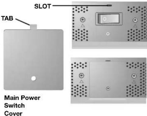
Main Power Switch Cover
Included with the display is a cover for the Main Power Switch. Use this cover to prevent the unit from being inadvertently powered off.
Place the tab on the cable cover into the rectangular slot on the display.
Th en using the screw provided, secure the cover to the display.
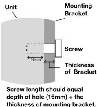
REMOTE CONTROL ID
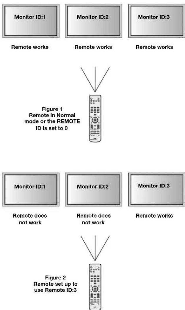
The remote control included with the display can be used to control up to 26 individual monitors using what is called the REMOTE CONTROL ID mode. The REMOTE CONTROL ID mode works in conjunction with the Monitor ID, allowing control of up to 26 individual monitors. For example: if there are many monitors being used in the same area, a remote control in normal mode would send signals to every monitor at the same time Figure 1. Using the remote in REMOTE CONTROL ID mode will only operate one specific monitor within the group Figure 2.
TO SET REMOTE CONTROL ID:
While holding down the REMOTE ID SET button on the remote control, use the KEYPAD to input the Monitor ID (1-26) of the display to be controlled via remote. The remote can then be used to operate the monitor having that specific Monitor ID number.
When 0 is selected or when the remote control is in normal mode, all monitors will be operated.
TO USE REMOTE CONTROL ID MODE
ID Mode - To enter ID Mode press the REMOTE ID SET button and hold down for 2 seconds.
Normal Mode - To return to Normal Mode press the REMOTE ID RESET button and hold down for 2 seconds.
In order for this feature to work properly, the display must be assigned a Monitor ID number. The Monitor ID number can be assigned under the OPTION3 menu in the OSD (See page 17).
If monitor ID is set to "ALL", monitor is controlled by remote control not depend on remote ID.
Remote Control ID Function
On-Screen Display (OSD)
Using the OSD
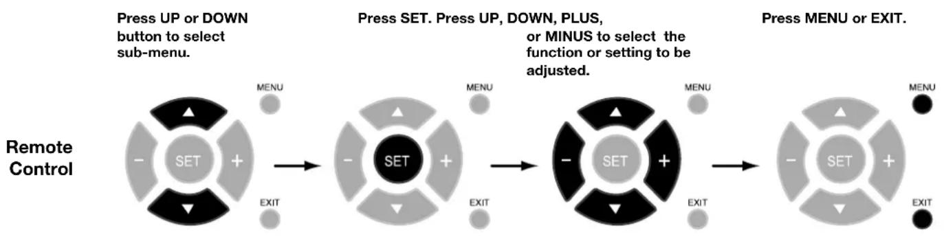
Use the Remote Control or the control panel on the front of the unit to enter the on-screen display menu to adjust settings.
- Press the MENU button on the remote or the EXIT button on the Control Panel.
- Use the up and down buttons to select the desired menu.
-
Press the SET button to select a sub-menu or item for adjustment.
-
Change the setting or adjustment by pressing the + and - buttons on the Control Panel or the Remote Control.
- Press the EXIT button on the Remote Control, on the Control Panel to return to the previous menu.
NOTE: Not all menu functions may be available. To access all functions the Advanced OSD option must be turned on in the ADVANCED OSD menu.
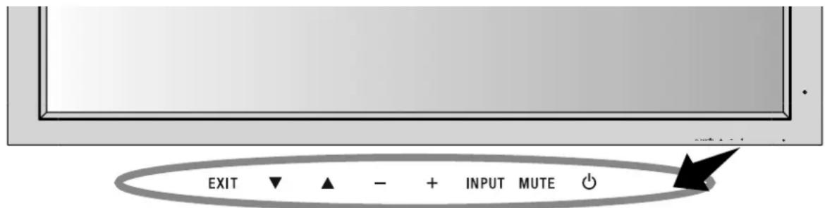
Control Panel
Press UP or DOWN button to select.
Press INPUT button to decide.
Press UP, DOWN, PLUS, or MINUS to select.
Press EXIT.

OSD Screen
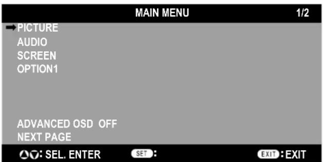
ADVANCED OSD is OFF. Not all OSD functions will be available when the ADVANCED OSD is off.
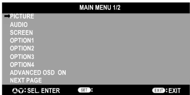
Advanced OSD is ON. All OSD functions are shown, but some OSD functions may not be available.
On-Screen Display (OSD)
| Main Menu Sub | Menu Sub Menu2 Sub | Menu3 Explanation | Default Reset | |||
| PICTURE CONTRAST Adjusts the image brightness in rela | white level. Press + or - to adjust. | 50 YES | ||||
| BRIGHTNESS Adjusts the image brightness in rela | ship to the background. Press + or - to adjust. | 50 YES | ||||
| SHARPNESS Adjusts the crispness of the image. Press | + or - to adjust. 50 YES | |||||
| COLOR Adjusts the color depth of the screen. Press + or | - to adjust. | 50 YES | ||||
| TINT | Adjusts the tint of the screen. Press + or - to adjust. | 50 | YES | |||
| PICTURE MODE | Selects picture mode, [BRIGHT], [STANDARD], [CINEMA1], [CINEMA2], [DEFAULT]. STANDARD: For watching in a bright room. CINEMA1, 2: For watching in a dark room, especially good for movies. BRIGHT: Brighter picture than STANDARD. DEFAULT: Restores factory default settings. | STANDARD | YES | |||
| NR | Adjusts the amount of noise reduction. Press + or - to adjust. | OFF | YES | |||
| COLOR TEMP. | Adjusts the color temperature of the entire screen. A low color temperature will make the screen reddish. A high color temperature will make the screen bluish. | MID | YES | |||
| WHITE BALANCE Available only when the Advanced OSD function is enabled. | GAIN RED | The "WHITE BALANCE" appears when the SET button is pressed on the "COLOR TEMP." OSD menu. | 50 YES | |||
| GAIN GREEN | GAIN RED/GREEN/BLUE: Adjusts the white level of the white balance. | 50 YES | ||||
| GAIN BLUE | 50 YES | |||||
| RESET | Reset the factory default settings. Select "ON", then press the SET button to reset. | OFF | YES | |||
| GAMMA Available only when the Advanced OSD function is enabled. | Select a display gamma for best picture quality. 2.1, 2.2, 2.3, 2.4: The picture becomes darker as the number increases. S: Special gamma for certain types of movies. Raises the dark parts and lowers the light parts of the image. (S-Curve) These values are approximate. | 2.2 | YES | |||
| COLOR CONTROL Available only when the Advanced OSD function is enabled. | RED | Adjusts the levels of the Red, Green, Blue, Yellow, Magenta and Cyan. VIDEO and DVD/HD input only. | 50 YES | |||
| GREEN | 50 YES | |||||
| BLUE | 50 YES | |||||
| YELLOW | 50 YES | |||||
| MAGENTA | 50 YES | |||||
| CYAN | 50 YES | |||||
| RESET | Reset the factory default settings. Select "ON", then press the SET button to reset. | OFF | YES | |||
| AUDIO | BASS | Adjusts the low frequency sound. Press + or - to adjust. | 0 | YES | ||
| TREBLE | Adjusts the high frequency sound. Press + or - to adjust. | 0 | YES | |||
| BALANCE | Adjusts the balance of L/R volume. Press + or - to adjust. | 0 | YES | |||
| AUDIO INPUT1 | Select which audio input to use with the video source. | VIDEO1 | YES | |||
| AUDIO INPUT2 | DVD/HD1 YES | |||||
| AUDIO INPUT3 | VGA | YES | ||||
On-Screen Display (OSD)
| Main Menu Sub | Menu Sub Menu2 Sub | Menu3 Explanation Default Reset | ||||
| SCREEN ASPECT | MODE Selects aspect ratio of the displayed image. Press + or - to select. | |||||
| V-POSITION Controls the vertical position of the image within the Display area of the PDP. Press + to move up. Press - to move down. | 0 | YES | ||||
| H-POSITION Controls the horizontal position of the image within the Display area of the PDP. Press + to move right. Press - to move left. | 0 | YES | ||||
| V-HEIGHT | Adjusts the vertical size of the image. | 0 | YES | |||
| H-WIDTH | Adjusts the horizontal size of the image. | 0 | YES | |||
| AUTO PICTURE | ON: H-Position, V-Position, Clock and Clock Phase are adjusted automatically. OFF: H-Position, V-Position, Clock and Clock Phase are adjusted manually. VGA and RGBHV input only. | OFF | NO | |||
| CLOCK PHASE | Adjusts the visual "noise" on the image. VGA and RGBHV input only. | 0 | YES | |||
| CLOCK | Press + to expand the width of the image on the right of the screen. Press - to narrow the width of the image on the left. VGA and RGBHV input only. | 0 | YES | |||
| UNDER SCAN Available only when the Advanced OSD function is enabled. | ON: UNDERSCAN is selectable in the ASPECT MODE menu. OFF: UNDERSCAN item is not selectable in the ASPECT MODE menu. Video signal input only. | OFF | YES | |||
| OPTION1 | OSD | DISPLAY OSD | ON: Information about inputs, screen size, etc. is shown. OFF: No information is shown. | ON | YES | |
| OSD POSITION | Change the position of the menu between 1 and 6. Press + or - to adjust. | 1 | YES | |||
| OSD ORBITER | ON: The menu position intermittently shifts eight dots while the OSD is being displayed. OFF: The menu position does not shift. | OFF | YES | |||
| OSD TRANSP. | Adjusts the transparency level of the OSD. Press + or - to adjust. | 70% | YES | |||
| BNC INPUT | Selects the input type when using 5BNC connectors. RGB: For RGB input. COMP.: For Component input (3BNC connectors). SCART1: For SCART input (4BNC connectors). SCART2: For SCART Input (3BNC connectors and VIDEO1 input). SCART1, SCART2 available for Europe and World-Wide models only. | RGB | YES | |||
| D-SUB INPUT | Selects the input type when using a mini D-SUB connector. RGB: For RGB input. SCART3: for SCART input. SCART3 available for Europe and World-Wide models only. | AUTO | YES | |||
| RGB SELECT | If there is a problem with signal detection, this function forces the monitor to display the signal at the desired resolution. If no problem is detected, the only available option will be "AUTO". VGA and RGBHV input only. | 1080B | NO | |||
| HD SELECT | Manually selects signal output when similar 1080I signal are detected. 1080B: Standard digital broadcasts. 1080A: Special digital broadcasts (ex. DTC100). | OFF | YES | |||
| INPUT SKIP | Skipping to next input if present input signal is not detected. This function is valid only for INPUT key on the display. | OFF | YES | |||
| ALL RESET | Reset settings back to factory default values. | OFF | ||||
On-Screen Display (OSD)
| Main Menu Sub | Menu Sub Menu2 Sub | Menu3 Explanation | Default Reset | |||
| OPTION2 Available only when the Advanced OSD function is enabled. | POWER SAVE Sets how long the monitor or waits before going into power save mode after a signal is lost. VGA, RGBHV, and DVI input and Separate HV Sync. only. | OFF YES | ||||
| FILM MODE Selects Film mode. ON YES | ||||||
| SCREEN Saver Use SCREEN Saver functions to reduce the risk of image retention. | ||||||
| PLE | PLE: The brightness is decreased in order of Lock mode. (the higher number is darker) | AUTO | YES | |||
| ORBITER | ORBITER: The screen image moves and is slightly squeezed or expanded. | AUTO1 | YES | |||
| INVERSE | WORKING TIME /WAITING TIME | INVERSE: The screen image is displayed alternately between positive image and negative image, or the screen image is displayed full white. | OFF YES | |||
| COOLING FAN | Cooling fan reduces the temperature of the display. | AUTO | NO | |||
| SIDE MASK | Adjusts the color of the side mask when a 4:3 image is displayed. Press + button, the bar will become lighter. Press - button, the bar will become darker. | 3 | YES | |||
| PICTURE SIZE | When it is set to "OFF", TRUE of picture size appears only RGB signals. | ON | YES | |||
| DVI MODE | PLUG/PLAY | Choose the DVI mode based on the input device connected via DVI connector and set the black level. When a PC or similar equipment is connected, the PLUG/PLAY setting should be "DVI-PC" and the BLACK LEVEL setting should be "LOW". When a DVD player or similar equipment is connected, PLUG/PLAY setting should be "DVI-HD" and the BLACK LEVEL setting should be "HIGH". | DVI-PC | NO | ||
| BLACK LEVEL | LOW | NO | ||||
| PROTOCOL SET | Sets protocol setting for use with RS-232C connection. OFF: When NEC protocol is used (normal). ON: When special protocol is used. Consult dealer for details of protocol. | OFF YES | ||||
| CLOSED CAPTION U.S. models only | Choose the closed caption setting. | OFF | YES | |||
| CAPTION CONT U.S. models only | Chooses the brightness of the closed captions. | NORMAL | YES | |||
| OPTION3 Available only when the Advanced OSD function is enabled. | TIMER | PRESENT TIME | DAYLIGHT SAVING TIME | Sets the date, time, and daylight saving region. Day & time must be set in order for the "TIMER" function to operate. | OFF | NO |
| DAY/HOUR/MINUTE | NO | |||||
| TIMER | Creates a working schedule for the monitor to use. See page 24 for instructions. | OFF YES | ||||
| INPUT DETECT | INPUT | Sets the input mode and the sound volume when the power is turned on. LAST: Uses the input that was last selected when the power was turned off. MULTI to DVI: Fixed input mode. AUTO: Automatically searches for the input signal. PRIORITY: Sets which input has priority when using the AUTO setting. | LAST | YES | ||
| VOLUME | LAST | YES | ||||
| CONTROL LOCK | This function completely locks out access to all Control Key functions. When this item is set to "ON", the front panel is disabled as soon as the on-screen menu goes off. | OFF YES | ||||
| IR REMOTE | When "OFF", prevents the monitor from being controlled by wireless remote controller. The remote becomes ineffective disabled as soon as the on-screen menu goes off. To return to normal operation, press the "DISPLAY" button on the remote controller for 5 seconds. | ON | YES | |||
| LOOP OUT | Change the loop out setting. | OFF YES | ||||
| MONITOR ID | Sets the Monitor ID to a number from 1-26 and or to ALL. | ALL | YES | |||
| RS232C CONTROL | Selects the mode of the monitor when using the RS-232C daisy chain. | NORMAL | YES | |||
On-Screen Display (OSD)
| Main Menu Sub | Menu Sub Menu2 Sub | Menu3 Explanation Default Reset | ||||
| OPTION3(continued) | VIDEO WALL Sets the confi guration of video wall. | |||||
| DIVIDER Sets the video wall. OFF YES | ||||||
| POSITION Sets the position of each display. | ||||||
| DISP. MODE Sets the mode of seam processing for each display. SPLIT YES | ||||||
| SCREEN | ASPECTMODE | Adjusts detail position. | ||||
| V-POSITION | 0 | YES | ||||
| H-POSITION | 0 | YES | ||||
| V-HEIGHT | 0 | YES | ||||
| H-WIDTH | 0 | YES | ||||
| AUTOPICTURE | OFF | YES | ||||
| CLOCKPHASE | 0 | YES | ||||
| CLOCK | 0 | YES | ||||
| UNDERSCAN | OFF | YES | ||||
| P.ON DELAY Adjusts the delay time between being in " standby" mode and entering "power on" mode. | OFF | YES | ||||
| OPTION4Available only when the Advanced OSD function is enabled. | SUB PICTURE | Automatically detects if there is an input signal for the sub screen. This feature is available only picture-in-picture mode. | ||||
| SUB P.Detect | Automatically detects sub screen. | AUTO | YES | |||
| DISPLAY | Sets the appearance of the sub screen. | NORMAL | YES | |||
| SUB P.RATE | Sets the transparency of the sub screen. | 100% | YES | |||
| ZOOM NAV | Sets the position of the zoom navigation image. | BTM LFT | YES | |||
| PIC FREEZE | Sets the position of the captured still picture. | S BY S1 | YES | |||
| QUICK SWAP | Enables quick swapping of input. Sets which input terminals are used. | OFF | YES | |||
| SELECT1 | VIDEO1 | YES | ||||
| SELECT2 | VGA | YES | ||||
| TEXT INSERT | Allows text insertion within main screen. | OFF | YES | |||
| INPUT | Sets the input of text image of the VGA, RGBHV, and DVI. | VGA | YES | |||
| SUB P.Detect | Automatically detects sub screen. | AUTO | YES | |||
| DISPLAY | Sets the appearance of the sub screen. | NORMAL | YES | |||
| SUB P.RATE | Sets the transparency of the sub screen. | 100% | YES | |||
| ADVANCED OSM | ON: All menu items are shown for advanced users. OFF: Some of the advanced menu items are not shown. | OFF | YES | |||
| LANGUAGE | Select the language used by the OSD. | ENGLISH NO | ||||
| COLOR SYSTEM | The Color System that is used depends on the video format of the input signal.VIDEO input only. | AUTO | NO | |||
| SOURCE INFORMATION | Display information about the display: frequencies, polarities, etc. | |||||
No picture
- The signal cable should be properly connected to the display card/computer.
- The display card should be properly seated in its slot.
- Front Power Switch and computer power switch should be in the ON position.
- Check to make sure that a supported mode has been selected on the display card or system being used. (Please consult display card or system manual to change graphics mode.)
- Check the monitor and your display card with respect to compatibility and recommended settings.
- Check the signal cable connector for bent or pushed-in pins.
Power Button does not respond
- Unplug the power cord of the monitor from the AC outlet to turn off and reset the monitor.
Image persistence
- Please be aware that Plasma Technology may experience a phenomena known as Image Persistence. Image Persistence occurs when a residual or "ghost" image of a previous image remains visible on the screen. Unlike CRT monitors, Plasma monitors' image persistence is not permanent, but constant images being displayed for a long period of time should be avoided. To alleviate image persistence, turn off the monitor for as long as the previous image was displayed. For example, if an image was on the monitor for one hour and a residual image remains, the monitor should be turned off for one hour to erase the image.
NOTE: As with all personal display devices, NEC DISPLAY SOLUTIONS recommends displaying moving images and using a moving screen saver at regular intervals whenever the screen is idle or turning off the monitor when not in use.
Image is unstable, unfocused or
swimming is apparent
- Signal cable should be properly attached to the Plasma monitor, computer, or other input device.
- Use the OSD screen controls to focus and adjust display by increasing or decreasing the clock phase total. When the display mode is changed, the OSD Image Adjust settings may need to be readjusted.
- Check the monitor and your display card with respect to compatibility and recommended signal timings.
Image of component signal is greenish
- Check to see if the DVD/HD input connector is selected.
LED on monitor is not lit
(no green or red color can be seen)
- Main Power Switch should be in the ON position and power cord should be connected.
Red LED on monitor is blinking
- A certain failure might have occurred, please contact your nearest authorized NEC DISPLAY SOLUTIONS service facility.
Display image is not sized properly
- Use the OSD screen controls to increase or decrease the clock total.
- Check to make sure that a supported mode has been selected on the display card or system being used. (Please consult display card or system manual to change graphics mode.)
Selected resolution is not displayed properly
- Use OSD information to enter Information menu and confirm that the appropriate resolution has been selected. If not, select appropriate resolution.
No Sound
- Check to see if speaker cable is properly connected.
- Check to see if mute is activated.
- Check to see if volume is set at minimum.
NOTE: It is possible to play audio from a source that is different from the video source.
RS-232C does not work
- Check the PROTOCOL SET in the OPTION2 menu.
Remote Control does not work
- Make sure the batteries are inserted properly.
Test the batteries for strength/life. - Make sure to point the remote directly at the sensor on the monitor.
- Check if the remote is in Remote ID mode.
- The remote control may not function when in direct sunlight or when there is strong illumination on the remote sensor of the monitor.
- Check the IR REMOTE setting in the OPTION3 menu.
Specifications P42XP10
| PDP Module Diagonal: 42" /1058 mm | ||||
| Pixel Pitch 0.900 mm (W)/0.676 mm (II) | ||||
| Resolution 1024 x 768 | ||||
| Frequency Horizontal ANALOG: 15.625/15.734Hz | 1Z, 31.0k11z - 108.5kHz | |||
| DIGITAL: 15.625/15.734kHz, 31.0kHz - 91.1kHz | ||||
| Vertical 24Hz to 20.4Hz | ||||
| Panel Display Size 922 mm (W) x 519 mm (II)36.3 in (W) x 20.4 in (II) | ||||
| Input Signals DVI DVI-D 24pin Digital RGB DVI (HDCP) | ||||
| VGA60, SVGA60, XGA60, WXGA60, SXGA60, UXGA60*, 1920X1080* | ||||
| 0.7V p-p, Input Impedance 75 ohm | ||||
| VGA60, SVGA60, XGA60, WXGA60, SXGA60, UXGA60* | ||||
| Separate: TTL level (Pos./Neg.) | ||||
| Composite sync on Green Video: 0.3Vp-p Neg | ||||
| 0.7V p-p, Input Impedance 75 ohm | ||||
| GA60, SVGA60, XGA60, WXGA60, SXGA60, UXGA60* | ||||
| Separate: TTL level (Pos./Neg.) | ||||
| Composite sync on Green Video: 0.3Vp-p Neg | ||||
| Y: 1.0Vp-p/75ohm, Cb/Cr (Pb/Pr): 0.7Vp-p/75 ohm | ||||
| HDTV/DVD:1080p*, 1080i*, 720p@50Hz/60Hz,576p@50Hz, 480p@60Hz, 576i@50Hz, 480i@60Hz | ||||
| 0.3Vp-p/75ohm(PAL/SECAM) | ||||
| NTSC/PAL(B, G, M, N)/SECAM/4.43NTSC/PAL60 | ||||
| NTSC/PAL(B, G, M, N)/SECAM/4.43NTSC/PAL60 | ||||
| Y: 1.0Vp-p/75ohm C: 0.286Vp-p/75 ohm(NTSC),0.3Vp-p/75ohm(PAL/SECAM) | ||||
| NTSC/PAL(B, G, M, N)/SECAM/4.43NTSC/PAL60 | ||||
| Output Signal (VIDEO1 and VGA can also be used as OUTPUT terminals) | VGA | 15pin Mini D-sub | Analog RGB | Analog RGB Video: 0.7V p-p with 75 ohm terminated |
| VIDEO1 | BNC | Composite | Composite 1.0V p-p with 75 ohm terminated | |
| Audio | AUDIO Input | RCA (L/R) X3 | Analog Audio | Stereo L/R 0.5Vrms |
| Speaker Output External Speaker Jack 8W + 8W (8 ohm) | ||||
| External Control | RS-232C: IN | 9 Pin D-sub | ||
| RS-232C: OUT | 9 Pin D-sub (daisy chain) | |||
| Power Supply | 4.4-1.8A@100-240V AC, 50/601Hz | |||
| Operational Environment | Temperature | 0' to 40'C / 32' F to 104' F | ||
| Humidity | 20% to 80% (without condensation) | |||
| Storage Environment | Temperature | -10°C to 50°C / 14' F to 122' F | ||
| Humidity | 10 - 90% (without condensation)/ 90% - 2% x (Temp - 40°C) regarding over 40°C | |||
| Dimensions | Net | 1036mm(W) x 644mm(H) x 127mm(D) / 40.8"(W) x 25.4"(H) x 5.0"(D) | ||
| Gross | 1220mm(W) x 900mm(H) x 360mm(D) / 48.0"(W) x 35.4"(H) x 14.2"(D) | |||
| Weight(without speaker and stand) | Net | 33.5 kg / 73.9 lbs | ||
| Gross | 41.5 kg / 91.5 lbs | |||
| VESA compatible armmounting interface | 700mm x 300mm 4.1Ioles (screw M8 Depth 16mm) | |||
| Complied Regulatory and Guidelines | UL 60950-1/CSA C22.2 No.60950-1/EN60950-1/IEC60950-1FCC-B/DOC-B/EN55022-B/EN55024/EN61000-3-2/EN61000-3-3/CE/C-Tick | |||
| Power Management | VESA DPM (Separate HV Sync. only) | |||
| Plug & Play | VESA DDC2B | |||
| Accessories | Remote control, AA Batteries, Power cord, Users Manual (CD-ROM),Start Up Guide (Paper / CD-ROM), Main Power Switch cover and screw, Cable clamps | |||
| *Compressed Image | ||||
Specifications P50XP10
| PDP Module Diagonal: 50°/1 | 269 mm | |||
| Pixel Pitch 0.81 mm (W)/0.81 mm (II) | ||||
| Resolution 1365 x 768 | ||||
| Frequency Horizontal ANALOG: 15.625/15.734 | DIGITAL: 15.625/15.734kHz, 31.0kHz - 91.1kHz | |||
| Vertical 24Hz to 120.4Hz | ||||
| Panel Display Size 1106 mmW) x 622 mm (II)43.5 in (W) x 24.5 in (II) | ||||
| Input Signals DVI DVI-D 24pin Digital RGB DVI (HDCP) | ||||
| VGA60, SVGA60, XGA60, WXGA60, SXGA60, UXGA60*, 1920X1080* | ||||
| VGA60, SVGA60, XGA60, WXGA60, SXGA60, UXGA60* | ||||
| Composite sync on Green Video: 0.3Vp-p Neg | ||||
| VGA60, SVGA60, XGA60, WXGA60, SXGA60, UXGA60* | ||||
| Composite sync on Green Video: 0.3Vp-p Neg | ||||
| VDI/DHD, RCA (Y, Cb/Pb, Cr/Pr) Component Y: 1.0Vp-p/75ohm, Cb/Cr (Pb/Pr) : 0.7Vp-p/75 ohm | ||||
| HDTV/DVD:1080p*, 1080i*, 720p@50Hz/60Hz,576p@501Hz, 480p@601Hz, 576i@501Hz, 480i@601Hz | ||||
| VIDEO1 OUT: 1.0V p-p Input Impedance 75 ohmNTSC/PAL60 | ||||
| VIDEO2 Composite sync: 1.0V p-p Input Impedance 75 ohmNTSC/PAL60 | ||||
| S-VIDEO DIN 4 pin S-VIDEO Compositio Y: 1.0Vp-p/75ohm C: 0.286Vp-p/75 ohm(NTSC),0.3Vp-p/75ohm(PAL/SECAM)NTSC/PAL(B, G, M, N)/SECAM/4.43NTSC/PAL60 | ||||
| Video1 OUT: 1.0V p-p with 75 ohm terminatedSeparate HV sync: TTI level (Pos / Neg) | ||||
| Output Signal (VIDEO1 and VGA can also be usedas OUTPUT terminals) | VGA | 15pin Mini D-sub | Analog RGB | Analog RGB Video: 0.7V p-p with 75 ohm terminatedSeparate HV sync: TTI level (Pos / Neg) |
| VIDEO1 | BNC | Composite | Composite 1.0V p-p with 75 ohm terminated | |
| Audio | AUDIO Input | RCA (L/R) X3 | Analog Audio | Stereo L/R 0.5Vrms |
| Speaker Output External Speaker Jack 8W + 8W (8 ohm) | ||||
| External Control | RS-232C: IN | 9 Pin D-sub | ||
| RS-232C: OUT | 9 Pin D-sub (daisy chain) | |||
| Power Supply | 6.0-2.6A@100-240V AC, 50/601Hz | |||
| Operational Environment | Temperature | 0° to 40°C / 32°F to 104°F | ||
| Humidity | 20% to 80% (without condensation) | |||
| Storage Environment | Temperature | -10°C to 50°C / 14°F to 122°F | ||
| Humidity | 10 - 90% (without condensation)/ 90% - 2% x (Temp - 40°C) regarding over 40°C | |||
| Dimensions | Net | 1221mm(W) x 743mm(H) x 127mm(D) / 48.1"(W) x 29.3"(H) x 5.0"(D) | ||
| Gross | 1400mm(W) x 980mm(H) x 360mm(D) / 55.1"(W) x 38.6"(H) x 14.2"(D) | |||
| Weight(without speaker and stand) | Nct | 47.5 kg / 104.7 lbs | ||
| Gross | 57.5 kg / 126.8 lbs | |||
| VESA compatible armmounting interface | 700mm x 300mm 4 I Ioles (screw M8 Depth 16mm) | |||
| Complied Regulatoryand Guidelines | UL 60950-1/CSA C22.2 No.60950-1/EN60950-1/IEC60950-1FCC-B/DOC-B/EN55022-B/EN55024/EN61000-3-2/EN61000-3-3/CE/C-Tick | |||
| Power Management | VESA DPM (Separate HV Sync. only) | |||
| Plug & Play | VESA DDC2B | |||
| Accessories | Remote control, AA Batteries, Power cord, Usrs Manual (CD-ROM),Start Up Guide (Paper / CD-ROM), Main Power Switch cover and screw; Cable clamps | |||
| *Compressed Image | ||||
Specifications P6oXP10
| PDP Module Diagonal: 60°/1514 mm | ||||
| Pixel Pitch 0.966 mm (W)/0.966 mm (II) | ||||
| Resolution 1366x768 | ||||
| Frequency Horizontal ANALOG: 15.625/15.734Hz | 1Hz, 31.0k1Hz - 108.5kHz | |||
| DIGITAL: 15.625/15.734kHz, 31.0kHz - 91.1kHz | ||||
| Vertical 24Hz to 20.4Hz | ||||
| Panel Display Size 1320 mm (W) x 742 mm (II)51.9 in (W) x 29.2 in (II) | ||||
| Input Signals DVI DVI-D 24pin Digital RGB DVI (HDCP) | ||||
| VGA60, SVGA60, XGA60, WXGA60, SXGA60, UXGA60*, 1920X1080* | ||||
| VGA60, SVGA60, XGA60, WXGA60, SXGA60, UXGA60* | ||||
| Composite sync on Green Video: 0.3Vp-p Neg | ||||
| VGA60, SVGA60, XGA60, WXGA60, SXGA60, UXGA60* | ||||
| Composite sync on Green Video: 0.3Vp-p Neg | ||||
| Y: 1.0Vp-p/75ohm, Cb/Cr (Pb/Pr): 0.7Vp-p/75 ohm | ||||
| HDTV/DVD:1080p*, 1080i*, 720p@50Hz/60Hz,576p@50Hz, 480p@60Hz, 576i@50Hz, 480i@60Hz | ||||
| NTSC/PAL(B, G, M, N)/SECAM/4.43NTSC/PAL60 | ||||
| NTSC/PAL(B, G, M, N)/SECAM/4.43NTSC/PAL60 | ||||
| NTSC/PAL(B, G, M, N)/SECAM/4.43NTSC/PAL60 | ||||
| Output Signal (VIDEO1 and VGA can also be used as OUTPUT terminals) | VIDEO1 | BNC | Composite | 1.0V p-p Input Impedance 75 ohm |
| NTSC/PAL(B, G, M, N)/SECAM/4.43NTSC/PAL60 | ||||
| VIDEO2 | RCA | Composite | 1.0V p-p Input Impedance 75 ohm | |
| NTSC/PAL(B, G, M, N)/SECAM/4.43NTSC/PAL60 | ||||
| S-VIDEO | DIN 4 pin | S-VIDEO | Y: 1.0Vp-p/75ohm C: 0.286Vp-p/75 ohm(NTSC),0.3Vp-p/75ohm(PAL/SECAM) | |
| NTSC/PAL(B, G, M, N)/SECAM/4.43NTSC/PAL60 | ||||
| Speaker Output External Speaker Jack 8W + 8W (8 ohm) | ||||
| External Control | RS-232C: IN | 9 Pin D-sub | ||
| RS-232C: OUT | 9 Pin D-sub (daisy chain) | |||
| Power Supply | 7.8-3.2A@100-240V AC, 50/601Hz | |||
| Operational Environment | Temperature | 0' to 40'C / 32' F to 104' F | ||
| Humidity | 20% to 80% (without condensation) | |||
| Storage Environment | Temperature | -10°C to 50°C / 14' F to 122' F | ||
| Humidity | 10 - 90% (without condensation)/ 90% - 2% x (Temp - 40°C) regarding over 40°C | |||
| Dimensions | Net | 1447(W)mm x 871mm(H) x 127mm(D) / 57.0"(W) x 34.3"(H) x 5.0"(D) | ||
| Gross | 1620mm(W) x 1100mm(H) x 360mm(D) / 63.8"(W) x 43.3"(H) x 14.2"(D) | |||
| Weight(without speaker and stand) | Net | 68.5 kg / 151.0 lbs | ||
| Gross | 81.0 kg / 178.6 lbs | |||
| VESA compatible armmounting interface | 700mm x 300mm 4.1Ioles (screw M8 Depth 16mm) | |||
| Complied Regulatory and Guidelines | UL 60950-1/CSA C22.2 No.60950-1/EN60950-1/IEC60950-1FCC-B/DOC-B/EN55022-B/EN55024/EN61000-3-2/EN61000-3-3/CE/C-Tick | |||
| Power Management | VESA DPM (Separate HV Sync. only) | |||
| Plug & Play | VESA DDC2B | |||
| Accessories | Remote control, AA Batteries, Power cord, Users Manual (CD-ROM),Start Up Guide (Paper / CD-ROM), Main Power Switch cover and screw, Cable clamps | |||
| *Compressed Image | ||||
P42XP10 Supported Resolutions (PC)
A gen Digital TEXT INSERT
| Sig. no. | Resolut h X V | Specification of the signal | INPUT jz mbit/s | SIZE | INPUT terminal | SIZE | TOP1-3/MID HIGH/ MID LOW/BOTTM1-3 | Left/Right | Sync polarity | RGB select | |||||||||||
| Signal Type | Filep (HZ) | Hreq. (kh) | NORMAL (4.3) | FULL (16.9) | ZOOM | TRUE (RE AL) | TRUE (REAL) | H | V | Gr, No. | Ite | ||||||||||
| IBM PCAT Compatible Computers | 1 | 640 X 400 | 400line | 70.1 | 31.5 | VGA RGBHV | -- | Yes | -- | -- | DVI (DVI-PC) | -- | -- | -- | -- | Yes | Yes | Neg. | Neg. | 1 | 640X400 |
| 2 | 720 X 400 | 400line | 70.1 | 31.5 | -- | Yes | -- | Yes | -- | Yes | -- | Yes | Yes | Yes | Neg. | Neg. | 1 | 720X400 | |||
| 3 | 85 | 37.9 | -- | Yes | -- | Yes | -- | Yes | -- | Yes | Yes | Yes | Neg. | Pos. | -- | -- | |||||
| 4 | 720 X 350 | 350line | 70.1 | 31.5 | -- | Yes | -- | Yes | -- | Yes | -- | Yes | Yes | Yes | Neg. | Neg. | 1 | 720X350 | |||
| 5 | 85 | 37.9 | Yes | Yes | Yes | Yes | Yes | Yes | Yes | Yes | Yes | Yes | Neg. | Neg. | 2 | 640X450 | |||||
| 6 | 640 X 480 | VGA | 75 | 37.5 | Yes | Yes | Yes | Yes | Yes | Yes | Yes | Yes | Yes | Yes | Neg. | Neg. | -- | -- | |||
| 7 | 85 | 43.3 | Yes | Yes | Yes | Yes | Yes | Yes | Yes | Yes | Yes | Yes | Neg. | Neg. | -- | -- | |||||
| 8 | 100.4 | 51.1 | Yes | Yes | Yes | Yes | Yes | Yes | Yes | Yes | Yes | Yes | Neg. | Neg. | -- | -- | |||||
| 9 | 120.4 | 61.3 | Yes | Yes | Yes | Yes | Yes | Yes | Yes | Yes | Yes | Yes | Neg. | Neg. | -- | -- | |||||
| 10 | 848 X 480 | Wide-VGA | 60 | 13 | -- | Yes | -- | Yes | Yes | Yes | Pos. | Pos. | 2 | 848X480 | |||||||
| 11 | 852 X 480 | Wide-VGA | 60 | 31.7 | -- | Yes | -- | Yes | Yes | Yes | Neg. | Neg. | 2 | 852X480 | |||||||
| 12 | 800 X 600 | SVGA | 56.3 | 35.2 | Yes | Yes | Yes | Yes | Yes | Yes | Pos. | Pos. | -- | -- | |||||||
| 13 | 61 | 60.3 | 37.9 | Yes | Yes | Yes | Yes | Yes | Yes | Pos. | Pos. | -- | -- | ||||||||
| 14 | 72.2 | 48.1 | Yes | Yes | Yes | Yes | Yes | Yes | Pos. | Pos. | -- | -- | |||||||||
| 15 | 646 | No | Yes | Yes | Yes | Yes | Yes | Pos. | Pos. | -- | -- | ||||||||||
| 16 | 85.1 | 53.7 | Yes | Yes | Yes | Yes | Yes | Yes | Pos. | Pos. | -- | -- | |||||||||
| 17 | 99.8 | 53 | Yes | Yes | Yes | Yes | Yes | Yes | Pos. | Pos. | -- | -- | |||||||||
| 18 | 20 | 75.7 | Yes | Yes | Yes | Yes | Yes | Yes | Pos. | Pos. | -- | -- | |||||||||
| 19 | 60 | 48.4 | Yes | Yes | Yes | -- | Yes | Yes | Neg. | Neg. | 3 | 1024X768 | |||||||||
| 20 | 70.1 | 56.5 | Yes | Yes | Yes | -- | Yes | Yes | Neg. | Neg. | 5 | 1024X768 | |||||||||
| 21 | 120 | 75.9 | Yes | Yes | Yes | -- | Yes | Yes | Neg. | Neg. | 6 | 1024X768 | |||||||||
| 22 | 57 | 96 | Yes | Yes | Yes | -- | Yes | Yes | Pos. | Pos. | -- | -- | |||||||||
| 23 | 85 | 68.7 | Yes | Yes | Yes | -- | Yes | Yes | Pos. | Pos. | -- | -- | |||||||||
| 24 | 001 6 | 05 | Yes | Yes | Yes | -- | Yes | Yes | Neg. | Neg. | -- | -- | |||||||||
| 25 | 1 91 4 | 55 | Yes | Yes | Yes | -- | Yes | -- | Neg. | Neg. | -- | -- | |||||||||
| 26 | 1152 X 864 | XGA | 60 | 53.7 | Yes | Yes | Yes | -- | Yes | Yes | Pos. | Pos. | -- | -- | |||||||
| 27 | 72 | 64.9 | Yes | Yes | Yes | -- | Yes | Yes | Pos. | Pos. | -- | -- | |||||||||
| 28 | 75 | 67.5 | Yes | Yes | Yes | -- | Yes | Yes | Pos. | Pos. | -- | -- | |||||||||
| 29 | 1280 X 768 | Wide-XGA | 56.2 | 45.1 | -- | Yes | -- | -- | -- | Yes | Yes | Pos. | Pos. | -- | |||||||
| 30 | 59.8 | 48 | -- | Yes | -- | -- | Yes | Yes | Pos. | Neg. | 3 | 1280X768-1 | |||||||||
| 31 | 59.9 | 47.8 | -- | Yes | -- | -- | Yes | Yes | Neg. | Pos. | 3 | 1280X768-2 | |||||||||
| 32 | 69.8 | 56 | -- | Yes | -- | -- | Yes | Yes | Neg. | Pos. | 5 | 1280X768 | |||||||||
| 33 | 72 | 57.8 | -- | Yes | -- | -- | Yes | Yes | Pos. | Pos. | 6 | 1280X768 | |||||||||
| 34 | 1280 X 800 | Wide-XGA | 59.8 | 94 | -- | Yes | -- | -- | Yes | Yes | Neg. | Pos. | 4 | 1280X800 | |||||||
| 35 | 1280 X 854 | Wide-XGA | 60 | 53.1 | -- | Yes | -- | -- | Yes | Yes | Neg. | Neg. | -- | -- | |||||||
| 36 | 1280 X 950 | Wide-XGA | 60 | 50 | -- | Yes | Yes | -- | Yes | Yes | Pos. | Pos. | -- | -- | |||||||
| 37 | 1360 X 768 | Wide-XGA | 60 | 47.7 | -- | Yes | -- | -- | Yes | Yes | Pos. | Pos. | 3 | 1360X768 | |||||||
| 38 | 1376 X 768 | Wide-XGA | 59.9 | 48.3 | -- | Yes | -- | -- | Yes | Yes | Neg. | Pos. | 3 | 1376X768 | |||||||
| 39 | 1280 X 1024 | SXGA | 60 | 64 | Yes "1" Yes "2" Yes "3" Yes "4" Yes "5" Yes "6" Yes "7" Yes "8" Yes "9" Yes "10" Yes "11" Yes "12" Yes "13" Yes "14" Yes "15" Yes "16" Yes "17" Yes "18" Yes "19" Yes "20" Yes "21" Yes "22" Yes "23" Yes "24" Yes "25" Yes "26" Yes "27" Yes "28" Yes "29" Yes "30" Yes "31" Yes "32" Yes "33" Yes "34" Yes "35" Yes "36" Yes "37" Yes "38" Yes "39" Yes "40" Yes "41" Yes "42" Yes "43" Yes "44" Yes "45" Yes "46" Yes "47" Yes "48" Yes "49" Yes "50" Yes "51" Yes "52" Yes "53" Yes "54" Yes "55" Yes "56" Yes "57" Yes "58" Yes "59" Yes "60" Yes "61" Yes "62" Yes "63" Yes "64" Yes "65" Yes "66" Yes "67" Yes "68" Yes "69" Yes "70" Yes "71" Yes "72" Yes "73" Yes "74" Yes "75" Yes "76" Yes "77" Yes "78" Yes "79" Yes "80" Yes "81" Yes "82" Yes "83" Yes "84" Yes "85" Yes "86" Yes "87" Yes "88" Yes "89" Yes "90" Yes "91" Yes "92" Yes "93" Yes "94" Yes "95" Yes "96" Yes "97" Yes "98" Yes "99" Yes "100" Yes "101" Yes "102" Yes "103" Yes "104" Yes "105" Yes "106" Yes "107" Yes "108" Yes "109" Yes "110" Yes "111" Yes "112" Yes "113" Yes "114" Yes "115" Yes "116" Yes "117" Yes "118" Yes "119" Yes "120" Yes "121" Yes "122" Yes "123" Yes "124" Yes "125" Yes "126" Yes "127" Yes "128" Yes "129" Yes "130" Yes "131" Yes "132" Yes "133" Yes "134" Yes "135" Yes "136" Yes "137" Yes "138" Yes "139" Yes "140" Yes "141" Yes "142" Yes "143" Yes "144" Yes "145" Yes "146" Yes "147" Yes "148" Yes "149" Yes "150" Yes "151" Yes "152" Yes "153" Yes "154" Yes "155" Yes "156" Yes "157" Yes "158" Yes "159" Yes "160" Yes "161" Yes "162" Yes "163" Yes "164" Yes "165" Yes "166" Yes "167" Yes "168" Yes "169" Yes "170" Yes "171" Yes "172" Yes "173" Yes "174" Yes "175" Yes "176" Yes "177" Yes "178" Yes "179" Yes "180" Yes "181" Yes "182" Yes "183" Yes "184" Yes "185" Yes "186" Yes "187" Yes "188" Yes "189" Yes "190" Yes "191" Yes "192" Yes "193" Yes "194" Yes "195" Yes "196" Yes "197" Yes "198" Yes "199" Yes "200" Yes "201" Yes "202" Yes "203" Yes "204" Yes "205" Yes "206" Yes "207" Yes "208" Yes "209" Yes "210" Yes "211" Yes "212" Yes "213" Yes "214" Yes "215" Yes "216" Yes "217" Yes "218" Yes "219" Yes "220" Yes "221" Yes "222" Yes "223" Yes "224" Yes "225" Yes "226" Yes "227" Yes "228" Yes "229" Yes "230" Yes "231" Yes "232" Yes "233" Yes "234" Yes "235" Yes "236" Yes "237" Yes "238" Yes "239" Yes "240" Yes "241" Yes "242" Yes "243" Yes "244" Yes "245" Yes "246" Yes "247" Yes "248" Yes "249" Yes "250" Yes "251" Yes "252" Yes "253" Yes "254" Yes "255" Yes "256" Yes "257" Yes "258" Yes "259" Yes "260" Yes "261" Yes "262" Yes "263" Yes "264" Yes "265" Yes "266" Yes "267" Yes "268" Yes "269" Yes "270" Yes "271" Yes "272" Yes "273" Yes "274" Yes "275" Yes "276" Yes "277" Yes "278" Yes "279" Yes "280" Yes "281" Yes "282" Yes "283" Yes "284" Yes "285" Yes "286" Yes "287" Yes "288" Yes "289" Yes "290" Yes "291" Yes "292" Yes "293" Yes "294" Yes "295" Yes "296" Yes "297" Yes "298" Yes "299" Yes "300" Yes "301" Yes "302" Yes "303" Yes "304" Yes "305" Yes "306" Yes "307" Yes "308" Yes "309" Yes "310" Yes "311" Yes "312" Yes "313" Yes "314" Yes "315" Yes "316" Yes "317" Yes "318" Yes "319" Yes "320" Yes "321" Yes "322" Yes "323" Yes "324" Yes "325" Yes "326" Yes "327" Yes "328" Yes "329" Yes "330" Yes "331" Yes "332" Yes "333" Yes "334" Yes "335" Yes "336" Yes "337" Yes "338" Yes "339" Yes "340" Yes "341" Yes "342" Yes "343" Yes "344" Yes "345" Yes "346" Yes "347" Yes "348" Yes "349" Yes "350" Yes "351" Yes "352" Yes "353" Yes "354" Yes "355" Yes "356" Yes "357" Yes "358" Yes "359" Yes "360" Yes "361" Yes "362" Yes "363" Yes "364" Yes "365" Yes "366" Yes "367" Yes "368" Yes "369" Yes "370" Yes "371" Yes "372" Yes "373" Yes "374" Yes "375" Yes "376" Yes "377" Yes "378" Yes "379" Yes "380" Yes "381" Yes "382" Yes "383" Yes "384" Yes "385" Yes "386" Yes "387" Yes "388" Yes "389" Yes "390" Yes "391" Yes "392" Yes "393" Yes "394" Yes "395" Yes "396" Yes "397" Yes "398" Yes "399" Yes "400" Yes "401" Yes "402" Yes "403" Yes "404" Yes "405" Yes "406" Yes "407" Yes "408" Yes "409" Yes "410" Yes "411" Yes "412" Yes "413" Yes "414" Yes "415" Yes "416" Yes "417" Yes "418" Yes "419" Yes "420" Yes "421" Yes "422" Yes "423" Yes "424" Yes "425" Yes "426" Yes "427" Yes "428" Yes "429" Yes "430" Yes "431" Yes "432" Yes "433" Yes "434" Yes "435" Yes "436" Yes "437" Yes "438" Yes "439" Yes "440" Yes "441" Yes "442" Yes "443" Yes "444" Yes "445" Yes "446" Yes "447" Yes "448" Yes "449" Yes "450" Yes "451" Yes "452" Yes "453" Yes "454" Yes "455" Yes "456" Yes "457" Yes "458" Yes "459" Yes "460" Yes "461" Yes "462" Yes "463" Yes "464" Yes "465" Yes "466" Yes "467" Yes "468" Yes "469" Yes "469" Yes "470" Yes "471" Yes "472" Yes "473" Yes "474" Yes "475" Yes "476" Yes "477" Yes "478" Yes "479" Yes "480" Yes "481" Yes "482" Yes "483" Yes "484" Yes "485" Yes "486" Yes "487" Yes "488" Yes "489" Yes "490" Yes "491" Yes "492" Yes "493" Yes "494" Yes "495" Yes "496" Yes "497" Yes "498" Yes "499" Yes "500" Yes "501" Yes "502" Yes "503" Yes "504" Yes "505" Yes "506" Yes "507" Yes "508" Yes "509" Yes "510" Yes "511" Yes "512" Yes "513" Yes "514" Yes "515" Yes "516" Yes "517" Yes "518" Yes "519" Yes "520" Yes "521" Yes "522" Yes "523" Yes "524" Yes "525" Yes "526" Yes "527" Yes "528" Yes "529" Yes "530" Yes "531" Yes "532" Yes "533" Yes "534" Yes "535" Yes "536" Yes "537" Yes "538" Yes "539" Yes "540" Yes "541" Yes "542" Yes "543" Yes "544" Yes "545" Yes "546" Yes "547" Yes "548" Yes "549" Yes "550" Yes "551" Yes "552" Yes "553" Yes "554" Yes "555" Yes "556" Yes "557" Yes "558" Yes "559" Yes "560" Yes "561" Yes "562" Yes "563" Yes "564" Yes "565" Yes "566" Yes "567" Yes "568" Yes "569" Yes "570" Yes "571" Yes "572" Yes "573" Yes "574" Yes "575" Yes "576" Yes "577" Yes "578" Yes "579" Yes "580" Yes "581" Yes "582" Yes "583" Yes "584" Yes "585" Yes "586" Yes "587" Yes "588" Yes "589" Yes "590" Yes "591" Yes "592" Yes "593" Yes "594" Yes "595" Yes "596" Yes "597" Yes "598" Yes "599" Yes "600" Yes "601" Yes "602" Yes "603" Yes "604" Yes "605" Yes "606" Yes "607" Yes "608" Yes "609" Yes "610" Yes "611" Yes "612" Yes "613" Yes "614" Yes "615" Yes "616" Yes "617" Yes "618" Yes "619" Yes "620" Yes "621" Yes "622" Yes "623" Yes "624" Yes "625" Yes "626" Yes "627" Yes "628" Yes "629" Yes "630" Yes "631" Yes "632" Yes "633" Yes "634" Yes "635" Yes "636" Yes "637" Yes "638" Yes "639" Yes "640" Yes "641" Yes "642" Yes "643" Yes "644" Yes "645" Yes "646" Yes "647" Yes "648" Yes "649" Yes "650" Yes "651" Yes "652" Yes "653" Yes "654" Yes "655" Yes "656" Yes "657" Yes "658" Yes "659" Yes "660" Yes "661" Yes "662" Yes "663" Yes "664" Yes "665" Yes "666" Yes "667" Yes "668" Yes "669" Yes "670" Yes "671" Yes "672" Yes "673" Yes "674" Yes "675" Yes "676" Yes "677" Yes "678" Yes "679" Yes "680" Yes "681" Yes "682" Yes "683" Yes "684" Yes "685" Yes "686" Yes "687" Yes "688" Yes "689" Yes "690" Yes "691" Yes "692" Yes "693" Yes "694" Yes "695" Yes "696" Yes "697" Yes "698" Yes "699" Yes "700" Y 601 602 603 604 605 606 607 608 609 610 611 612 613 614 615 616 617 618 619 620 621 622 623 624 625 626 627 628 629 630 631 632 633 634 635 636 637 638 639 640 641 642 643 644 645 646 647 648 649 650 651 652 653 654 655 656 657 658 659 660 661 662 663 664 665 666 667 668 669 670 671 672 673 674 675 676 677 678 679 680 681 682 683 684 685 686 687 688 689 690 691 692 693 694 695 696 697 698 699 700 701 702 703 704 705 706 707 708 709 710 711 712 713 714 715 716 717 718 719 720 721 722 723 724 725 726 727 728 729 730 731 732 733 734 735 736 737 738 739 740 741 742 743 744 745 746 747 748 749 750 751 752 753 754 755 756 757 758 759 759 760 761 762 763 764 765 766 767 768 769 770 771 772 773 774 775 776 777 778 779 780 781 782 783 784 785 786 787 788 789 790 791 792 793 794 795 796 797 798 799 800 801 802 803 804 805 806 807 808 809 810 811 812 813 814 815 816 817 818 819 820 821 822 823 824 825 826 827 828 829 830 831 832 833 834 835 836 837 838 839 840 841 842 843 844 845 846 847 848 849 850 851 852 853 854 855 856 857 858 859 860 861 862 863 864 865 866 867 868 869 870 871 872 873 874 875 876 877 878 879 880 881 882 883 884 885 886 887 888 889 890 891 892 893 894 895 896 897 898 899 900 901 902 903 904 905 906 907 908 909 910 911 912 913 914 915 916 917 918 919 920 921 922 923 924 925 926 927 928 929 930 931 932 933 934 935 936 937 938 939 940 941 942 943 944 945 946 947 948 949 950 951 952 953 954 955 956 957 958 959 960 961 962 963 964 965 966 967 968 969 970 971 972 973 974 975 976 977 978 979 980 981 982 983 984 985 986 987 988 989 990 991 992 993 994 995 996 997 998 999 100 X 999 X 100 X 999 X 101 X 999 X 102 X 999 X 103 X 999 X 104 X 999 X 105 X 999 X 106 X 999 X 107 X 999 X 108 X 999 X 109 X 999 X 110 X 999 X 111 X 999 X 112 X 999 X 113 X 999 X 114 X 999 X 115 X 999 X 116 X 999 X 117 X 999 X 118 X 999 X 119 X 999 X 120 X 999 X 121 X 999 X 122 X 999 X 123 X 999 X 124 X 999 X 125 X 999 X 126 X 999 X 127 X 999 X 128 X 999 X 129 X 999 X 130 X 999 X 131 X 999 X 132 X 999 X 133 X 999 X 134 X 999 X 135 X 999 X 136 X 999 X 137 X 999 X 138 X 999 X 139 X 999 X 140 X 999 X 141 X 999 X 142 X 999 X 143 X 999 X 144 X 999 X 145 X 999 X 146 X 999 X 147 X 999 X 148 X 999 X 149 X 999 X 150 X 999 X 151 X 999 X 152 X 999 X 153 X 999 X 154 X 999 X 155 X 999 X 156 X 999 X 157 X 999 X 158 X 999 X 159 X 999 X 160 X 999 X 161 X 999 X 162 X 999 X 163 X 999 X 164 X 999 X 165 X 999 X 166 X 999 X 167 X 999 X 168 X 999 X 169 X 999 X 170 X 999 X 171 X 999 X 172 X 999 X 173 X 999 X 174 X 999 X 175 X 999 X 176 X 999 X 177 X 999 X 178 X 999 X 179 X 999 X 180 X 999 X 181 X 999 X 182 X 999 X 183 X 999 X 184 X 999 X 185 X 999 X 186 X 999 X 187 X 999 X 188 X 999 X 189 X 999 X 190 X 999 X 191 X 999 X 192 X 999 X 193 X 999 X 194 X 999 X 195 X 999 X 196 X 999 X 197 X 999 X 198 X 999 X 199 X 100 X 999 X 101 X 999 X 102 X 999 X 103 X 999 X 104 X 999 X 105 X 999 X 106 X 999 X 107 X 999 X 108 X 999 X 109 X 100 X 999 X 110 X 999 X 111 X 999 X 112 X 999 X 113 X 999 X 114 X 999 X 115 X 999 X 116 X 999 X 117 X 999 X 118 X 999 X 115 X 999 X 116 X 999 X 117 X 999 X 118 X 999 X 119 X 999 X 120 X 999 X 121 X 999 X 122 X 999 X 123 X 999 X 125 X 999 X 126 X 999 X 127 X 999 X 128 X 999 X 129 X 999 X 130 X 999 X 131 X 999 X 132 X 999 X 133 X 999 X 135 X 999 X 136 X 999 X 137 X 999 X 138 X 999 X 139 X 999 X 140 X 999 X 141 X 999 X 142 X 999 X 143 X 999 X 145 X 999 X 146 X 999 X 147 X 999 X 148 X 999 X 149 X 999 X 150 X 999 X 151 X 999 X 152 X 999 X 153 X 999 X 155 X 999 X 156 X 999 X 157 X 999 X 158 X 999 X 159 X 999 X 160 X 999 X 161 X 999 X 162 X 999 X 163 X 999 X 165 X 999 X 166 X 999 X 167 X 999 X 168 X 999 X 169 X 999 X 170 X 999 X 171 X 999 X 172 X 999 X 173 X 999 X 175 X 999 X 176 X 999 X 177 X 999 X 178 X 999 X 179 X 999 X 180 X 999 X 181 X 999 X 182 X 999 X 183 X 999 X 185 X 999 X 186 X 999 X 187 X 999 X 188 X 999 X 189 X 999 X 190 X 999 X 191 X 999 X 192 X 999 X 193 X 999 X 195 X 999 X 196 X 999 X 197 X 999 X 198 X 999 X 199 X 100 X 999 X 100 X 999 X 101 X 999 X 102 X 999 X 103 X 999 X 104 X 999 X 105 X 999 X 106 X 999 X 107 X 999 X 108 X 999X 100 X 999 X 101 X 999 X 102 X 999 X 103 X 999 X 104 X 999 X 105 X 999 X 106 X 999 X 107 X 999 X 108 X 999 X 109 X 100X 101 X 999 X 102 X 999 X 103 X 999 X 104 X 999 X 105 X 999 X 106 X 999 X 107 X 999 X 108 X 999 X 109 X 100 X 999 X 102 X 999 X 103 X 999 X 104 X 999 X 105 X 999 X 106 X 999 X 107 X 999 X 108 X 999 X 109 X 100 X 999 X 102 X 998 X 103 X 998 X 104 X 998 X 105 X 998 X 106 X 998 X 107 X 998 X 109 X 100 X 998 X 102 X 998 X 103 X 998 X 104 X 998 X 105 X 998 X 106 X 998 X 107 X 998 X 108 X 998 X 109 X 100 X 998 X 102 X 998 X 103 X 998 X 104 X 998 X 105 X 998 X 106 X 998 X 107 X 998 X 108 X 998 X 109 X 101 X 998 X 102 X 998 X 103 X 998 X 104 X 998 X 105 X 998 X 106 X 998 X 107 X 998 X 108 X 998 X 109 X 100 X 998 X 102 X 997 X 100 X 998 X 103 X 998 X 104 X 998 X 105 X 998 X 106 X 998 X 107 X 998 X 108 X 998 X 109 X 100 X 998 X 102 X 998 X 103 X 997 X 100 X 998 X 104 X 998 X 105 X 998 X 106 X 998 X 107 X 998 X 108 X 998 X 109 X 100 X 998 X 102 X 998 X 103 X 998 X 104 X 997 X 100 X 998 X 105 X 998 X 106 X 998 X 107 X 998 X 108 X 998 X 109 X 100 X 998 X 102 X 998 X 103 X 998 X 104 X 998 X 105 X 997 X 100 X 998 X 103 X 998 X 104 X 998 X 105 X 998 X 106 X 998 X 107 X 998 X 108 X 998 X 109 X 100 X 998 X 102 X 997 X 100 X 997 X 108 X 998 X 109 X 100 X 998 X 102 X 998 X 103 X 998 X 104 X 998 X 105 X 998 X 106 X 998 X 107 X 998 X 108 X 998 X 108 X 998 X 109 X 100 X 998 X 102 X 998 X 103 X 998 X 104 X 998 X 105 X 998 X 106 X 998 X 107 X 998 X 108 X 99B X 100 X 998 X 102 X 998 X 103 X 998 X 104 X 998 X 105 X 998 X 106 X 998 X 107 X 998 X 108 X 99B X 100 X 998 X 102 X 99B X 103 X 99B X 104 X 99B X 105 X 99B X 106 X 99B X 107 X 99B X 108 X 99B X 109 X 100 X 99B X 103 X 99B X 104 X 99B X 105 X 99B X 106 X 99B X 107 X 99B X 108 X 99B X 109 X 100 X 99B X 103 X 99B X 104 X 99 B X 105 X 99B X 106 X 99B X 107 X 99B X 108 X 99B X 109 X 100 X 99B X 103 X 99B X 104 X 99B X 105 X 99B X 106 X 99B X 108 X 99B X 109 X 100 X 99B X 103 X 99B X 104 X 99B X 105 X 99B X 106 X 99B X 107 X 99B X 108 X 99B X 109 X 101 X 99B X 103 X 99B X 104 X 99B X 105 X 99B X 106 X 99B X 107 X 99B X 108 X 99B X 109 X 100 X 99B X 103 X 99B X 104 X 99 BBX Y Y Y Y Y Y Y Y Y Y Y Y Y Y Y Y Y Y Y Y Y Y Y Y Y Y Y Y Y Y Y Y Y Y Y Y Y Y Y Y Y Y Y Y Y Y Y Y Y Y Y Y Y Y Y Y Y Y Y Y Y Y Y Y Y Y Y Y Y Y Y Y Y Y Y Y Y Y Y Y Y Y Y Y Y Y Y Y Y Y Y Y Y Y Y Y Y Y Y YY Y Y Y Y Y Y Y Y Y Y Y Y Y Y Y Y Y Y Y Y Y Y Y Y Y Y Y Y Y Y Y Y Y Y Y Y Y Y Y Y Y Y Y Y Y Y Y Y Y Y Y Y Y Y Y Y Y Y Y Y Y Y Y Y Y Y Y Y Y Y Y Y Y Y Y Y Y Y Y Y Y Y Y Y Y Y Y Y Y Y Y Y Y Y Y Y Y Y Y.Y Y Y Y Y Y Y Y Y Y Y Y Y Y Y Y Y Y Y Y Y Y Y Y Y Y Y Y Y Y Y Y Y Y Y Y Y Y Y Y Y Y Y Y Y Y Y Y Y Y Y Y Y Y Y Y Y Y Y Y Y Y Y Y Y Y Y Y Y Y Y Y Y Y Y Y Y Y Y Y Y Y Y Y Y Y Y Y Y Y Y Y Y Y Y Y Y Y Y Y YYYYYYYYYYYYYYYYYYYYYYYYYYYYYYYYYYYYYYYYYYYYYYYYYYYYYYYYYYYYYYYYYYYYYYYYYYYYYYYYYYYYYYYYYYYYYYYYYYYYYYYYYYYYYYYYYYYYYYYYYYYYYYYYYYYYYYYYYYYYYYYYYYYYYYYYYYYYYYYYYYYYYYYYYYYYYYYYYYYYYYYYYYYYYYYYYYYYYYYYYY YYYYYYYYYYYYYYYYYYYYYYYYYYYYYYYYYYYYYYYYYYYYYYYYYYYYYYYYYYYYYYYYYYYYYYYYYYYYYYYYYYYYYYYYYYYYYYYYYYYYYYYYYYYYYYYYYYYYYYYYYYYYYYYYYYYYYYYYYYYYYYYYYYYYYYYYYYYYYYYYYYYYYYYYYYYYYYYYYYYYYYYYYYYYYYYYYYYYYY YY YY YY YY YY YY YY YY YY YY YY YY YY YY YY YY YY YY YY YY YY YY YY YY YY YY YY YY YY YY YY YY YY YY YY YY YY YY YY YY YY YY YY YY YY YY YY YY YY YY YY YY YY YY YY YY YY YY YY YY YY YY YY YY YY YY YY YY YY YY YY YY YY YY YY YY YY YY YY YY YY YY YY YY YY YY YY YY YY YY YY YY YY YY YY YY YY YY YY YYYYYYYYYYYYYYYYYYYYYYYYYYYYYYYYYYYYYYYYYYYYYYYYYYYYYYYYYYYYYYYYYYYYYYYYYYYYYYYYYYYYYYYYYYYYYYYYYYYYYYYYYYYYYYYYYYYYYYYYYYYYYYYYYYYYYYYYYYYYYYYYYYYYYYYYYYYYYYYYYYYYYYYYYYYYYYYYYYYYYYYYYYYYYYYYYYYYYYyyYYYYYYYYYYYYYYYYYYYYYYYYYYYYYYYYYYYYYYYYYYYYYYYYYYYYYYYYYYYYYYYYYYYYYYYYYYYYYYYYYYYYYYYYYYYYYYYYYYYYYYYYYYYYYYYYYYYYYYYYYYYYYYYYYYYYYYYYYYYYYYYYYYYYYYYYYYYYYYYYYYYYYYYYYYYYYYYYYYYYYYYYYYYYYYYYYYYYYYyyyyyyyyyyyyyyyyyyyyyyyyyyyyyyyyyyyyyyyyyyyyyyyyyyyyyyyyyyyyyyyyyyyyyyyyyyyyyyyyyyyyyyyyyyyyyyyyyyyyyyyyyyyyyyyyyyyyyyyyyyyyyyyyyyyyyyyyyyyyyyyyyyyyyyyyyyyyyyyyyyyyyyyyyyyyyyyyyyyyyyyyyyyyyyyyyyyyyyyyYYYYYYYYYYYYYYYYYYYYYYYYYYYYYYYYYYYYYYYYYYYYYYYYYYYYYYYYYYYYYYYYYYYYYYYYYYYYYYYYYYYYYYYYYYYYYYYYYYYYYYYYYYYYYYYYYYYYYYYYYYYYYYYYYYYYYYYYYYYYYYYYYYYYYYYYYYYYYYYYYYYYYYYYYYYYYYYYYYYYYYYYYYYYYYYYYYYY YY yy yy yy yy yy yy yy yy yy yy yy yy yy yy yy yy yy yy yy yy yy yy yy yy yy yy yy yy yy yy yy yy yy yy yy yy yy yy yy yy yy yy yy yy yy yy yy yy yy yy yy yy yy yy yy yy yy yy yy yy yy yy yy yy yy yy yy yy yy yy yy yy yy yy yy yy yy yy yy yy yy yy yy yy yy yy yy yy yy yy yy yy yy yy yy yy yy yy yy yy YY YY YY YY YY YY YY YY YY YY YY YY YY YY YY YY YY YY YY YY YY YY YY YY YY YY YY YY YY YY YY YY YY YY YY YY YY YY YY YY YY YY YY YY YY YY YY YY YY YY YY YY YY YY YY YY YY YY YY YY YY YY YY YY YY YY YY YY YY YY YY YY YY YY YY YY YY YY YY YY YY YY YY YY YY YY YY YY YY YY YY YY YY YY YY YY YY YY YY BBX Y Y Y Y Y Y Y Y Y Y Y Y Y Y Y Y Y Y Y Y Y Y Y Y Y Y Y Y Y Y Y Y Y Y Y Y Y Y Y Y Y Y Y Y Y Y Y Y Y Y Y Y Y Y Y Y Y Y Y Y Y Y Y Y Y Y Y Y Y Y Y Y Y Y Y Y Y Y Y Y Y Y Y Y Y Y Y Y Y Y Y Y Y Y Y Y Y YY YY YY YY YY YY YY YY YY YY YY YY YY YY YY YY YY YY YY YY YY YY YY YY YY YY YY YY YY YY YY YY YY YY YY YY YY YY YY YY YY YY YY YY YY YY YY YY YY YY YY YY YY YY YY YY YY YY YY YY YY YY YY YY YY YY YY YY YY YY YY YY YY YY YY YY YY YY YY YY YY YY YY YY YY YY YY YY YY YY YY YY YY YY YY YY YY YY YY EEY EEEY EEEY EEEY EEEY EEEY EEEY EEEY EEEY EEEY EEEY EEEY EEEY EEEY EEEY EEEY EEEY EEEY EEEY EEEY EEEY EEEY EEEY EEEY EEEY EEEY EEEY EEEY EEEY EEEY EEEY EEEY EEEY EEEY EEE! | ||||||||||||||||
| - | NORMAL (4:3) | FULL(15:9) | (1') | (1'2) |
| Not Supported | 768 pixels x 768 lines | 1024 pixels x 768 lines | Aspect ratio is 5:4 (720x768) | Rough Sampling |
P42XP10 Supported Resolutions (Video)
Analog Digital
| Sig. no. | Resolution H X V | Signal Type | Specification of the signal | INPUT terminal | SIZE | INPUT terminal | SIZE | |||||||||||||||||||||||||||||||||||||||||||||||||||||||||||||||||||||||||||||||||||||||||||||||||||||||||||||||||||||||||||||||||||
| Vfreq (Hz) | H freq. (kHz) | NORMAL (4:3) | FULL (16:9) | DYNAMIC (non-linear) | ZOOM | 14:9 | 2.351 | UNDER SCAN | INPUT terminal | NORMAL (4:3) | FULL (16:9) | DYNAMIC (non-linear) | ZOOM | 14:9 | 2.351 | UNDER SCAN | INPUT terminal | NORMAL (4:3) | FULL (16:9) | DYNAMIC (non-linear) | ZOOM | 14:9 | 2.351 | UNDER SCAN | RGB select | HDs select | ||||||||||||||||||||||||||||||||||||||||||||||||||||||||||||||||||||||||||||||||||||||||||||||||||||||||||||||||
| Video Composite / S | 101 | 3.58NTSC | 59.9 | 15.8 | Video1 | Yes | Yes | Yes | Yes | Yes | Yes | Yes | Yes | Yes | 3 | |||||||||||||||||||||||||||||||||||||||||||||||||||||||||||||||||||||||||||||||||||||||||||||||||||||||||||||||||||||||||||
| 102 | 4.43NTSC | 59.9 | 15.8 | Video2 | Yes | Yes | Yes | Yes | Yes | Yes | Yes | Yes | Yes | 3 | ||||||||||||||||||||||||||||||||||||||||||||||||||||||||||||||||||||||||||||||||||||||||||||||||||||||||||||||||||||||||||||
| 103 | PAL | 50 | 15.6 | S-Video | Yes | Yes | Yes | Yes | Yes | Yes | Yes | Yes | Yes | 3 | ||||||||||||||||||||||||||||||||||||||||||||||||||||||||||||||||||||||||||||||||||||||||||||||||||||||||||||||||||||||||||||
| 104 | PAL50 | 58.9 | 15.8 | Video2 | Yes | Yes | Yes | Yes | Yes | Yes | Yes | Yes | Y c\* | |||||||||||||||||||||||||||||||||||||||||||||||||||||||||||||||||||||||||||||||||||||||||||||||||||||||||||||||||||||||||||||
| 105 | PAL-N | 50 | 15.6 | Video2 | Yes | Yes | Yes | Yes | Yes | Yes | Yes | Yes | Yes | 3 | ||||||||||||||||||||||||||||||||||||||||||||||||||||||||||||||||||||||||||||||||||||||||||||||||||||||||||||||||||||||||||||
| 106 | PAL-M | 59.9 | 1 8.5 | Video2 | Yes | Yes | Yes | Yes | Yes | Yes | Yes | Yes | Yes | 3 | ||||||||||||||||||||||||||||||||||||||||||||||||||||||||||||||||||||||||||||||||||||||||||||||||||||||||||||||||||||||||||||
| 107 | SECAM | 50 | 15.6 | Video2 | Yes | Yes | Yes | Yes | Yes | Yes | Yes | Yes | Yes | 3 | ||||||||||||||||||||||||||||||||||||||||||||||||||||||||||||||||||||||||||||||||||||||||||||||||||||||||||||||||||||||||||||
| Y,Pb(Cb),Pr(Cr) | SD | 111 | 480I | 59.9 | 15.8 | DVD/HD1 DVD/HD2 | Yes | Yes | Yes | Yes | Yes | Yes | Yes | Yes | 3 | |||||||||||||||||||||||||||||||||||||||||||||||||||||||||||||||||||||||||||||||||||||||||||||||||||||||||||||||||||||||||||
| 112 | 576I | 50 | 15.6 | Video2 | Yes | Yes | Yes | Yes | Yes | Yes | Yes | Yes | 3 | |||||||||||||||||||||||||||||||||||||||||||||||||||||||||||||||||||||||||||||||||||||||||||||||||||||||||||||||||||||||||||||
| 113 | 480P | 59.9 | 31.5 | Video2 | Yes | Yes | Yes | Yes | Yes | Yes | Yes | Yes | 3 | |||||||||||||||||||||||||||||||||||||||||||||||||||||||||||||||||||||||||||||||||||||||||||||||||||||||||||||||||||||||||||||
| 114 | 576P | 05 | 3.13 | Video2 | Yes | Yes | Yes | Yes | Yes | Yes | Yes | Yes | 3 | |||||||||||||||||||||||||||||||||||||||||||||||||||||||||||||||||||||||||||||||||||||||||||||||||||||||||||||||||||||||||||||
| HD | 115 | 720P | 50 | 37.5 | Video2 | -- | Yes | Yes | Yes | -- | -- | Yes | Yes | 3 | ||||||||||||||||||||||||||||||||||||||||||||||||||||||||||||||||||||||||||||||||||||||||||||||||||||||||||||||||||||||||||||
| 116 | 720P | 60 | 45 | Video2 | -- | Yes | Yes | Yes | -- | -- | Yes | Yes | 3 | |||||||||||||||||||||||||||||||||||||||||||||||||||||||||||||||||||||||||||||||||||||||||||||||||||||||||||||||||||||||||||||
| 117 | 1080I | 50 | 28.1 | Video2 | -- | Yes | Yes | Yes | -- | -- | Yes | Yes | 3 | |||||||||||||||||||||||||||||||||||||||||||||||||||||||||||||||||||||||||||||||||||||||||||||||||||||||||||||||||||||||||||||
| 118 | 1080I | 6 0 | 338 | Video2 | -- | Yes | Yes | Yes | -- | -- | Yes | Yes | 3 | |||||||||||||||||||||||||||||||||||||||||||||||||||||||||||||||||||||||||||||||||||||||||||||||||||||||||||||||||||||||||||||
| 119 | 1080P | 50 | 3.65 | Video2 | -- | Yes | Yes | Yes | -- | -- | Yes | Yes | 3 | |||||||||||||||||||||||||||||||||||||||||||||||||||||||||||||||||||||||||||||||||||||||||||||||||||||||||||||||||||||||||||||
| 120 | 1080P | 06 | 5.76 | Video2 | -- | Yes | Yes | Yes | -- | -- | Yes | Y c\* | 374 | -- | -- | -- | -- | -- | -- | -- | -- | -- | -- | -- | -- | -- | -- | -- | -- | -- | -- | -- | -- | -- | -- | -- | -- | -- | -- | -- | -- | -- | -- | -- | -- | -- | ||||||||||||||||||||||||||||||||||||||||||||||||||||||||||||||||||||||||||||||||||||||||||||
| 121 | 1080P | 03 | 33.8 | Video2 | -- | Yes | Y se | -- | -- | Yes | Y c\* | 374 | -- | -- | -- | -- | -- | -- | -- | -- | -- | -- | -- | -- | -- | -- | -- | -- | -- | -- | -- | -- | -- | -- | -- | -- | -- | -- | -- | -- | -- | -- | -- | |||||||||||||||||||||||||||||||||||||||||||||||||||||||||||||||||||||||||||||||||||||||||||||||
| 122 | 1080P | 42 | 72 | Video2 | -- | Yes | Y se | -- | -- | Yes | Yes | 374 | -- | -- | -- | -- | -- | -- | -- | -- | -- | -- | -- | -- | -- | -- | -- | -- | -- | -- | -- | -- | -- | -- | -- | -- | -- | -- | -- | -- | -- | |||||||||||||||||||||||||||||||||||||||||||||||||||||||||||||||||||||||||||||||||||||||||||||||||
| 123 | 1080P | 25 | 2 8 | Video2 | -- | Yes | a | Yes | -- | -- | Yes | Yes | 374 | -- | -- | -- | -- | -- | -- | -- | -- | -- | -- | -- | -- | -- | -- | -- | -- | -- | -- | -- | -- | -- | -- | -- | -- | -- | -- | |||||||||||||||||||||||||||||||||||||||||||||||||||||||||||||||||||||||||||||||||||||||||||||||||||
| RGB(Video signal) | SD | 131 | 480I *4 | 59.9 | 15.8 | VGA RGBHV (SCART1-3) Video2 | Yes | Yes | Yes | Yes | Yes | Yes | Yes | 374 | -- | -- | -- | -- | -- | -- | -- | -- | -- | -- | -- | -- | -- | -- | -- | -- | -- | -- | -- | -- | -- | -- | -- | -- | -- | -- | -- | |||||||||||||||||||||||||||||||||||||||||||||||||||||||||||||||||||||||||||||||||||||||||||||||||
| 132 | 576I *4 | 50 | 15.6 | Video2 | Yes | Yes | Yes | Yes | Yes | Yes | Yes | 374 | -- | -- | -- | -- | -- | -- | -- | -- | -- | -- | -- | -- | -- | -- | -- | -- | -- | -- | -- | -- | -- | -- | -- | -- | -- | -- | ||||||||||||||||||||||||||||||||||||||||||||||||||||||||||||||||||||||||||||||||||||||||||||||||||||
| 133 | 480P | 59.9 | 31.5 | Video2 | Yes | Yes | Yes | Yes | Yes | Yes | Yes | 374 | -- | -- | -- | -- | -- | -- | -- | -- | -- | -- | -- | -- | -- | -- | -- | -- | -- | -- | -- | -- | -- | -- | -- | -- | -- | -- | ||||||||||||||||||||||||||||||||||||||||||||||||||||||||||||||||||||||||||||||||||||||||||||||||||||
| 134 | 576P | 50 | 31.3 | Video2 | Yes | Yes | Yes | Yes | Yes | Yes | Yes | 374 | -- | -- | -- | -- | -- | -- | -- | -- | -- | -- | -- | -- | -- | -- | -- | -- | -- | -- | -- | -- | -- | -- | -- | -- | ||||||||||||||||||||||||||||||||||||||||||||||||||||||||||||||||||||||||||||||||||||||||||||||||||||||
| HD | 135 | 720P | 50 | 3 5.7 | Video2 | -- | Yes | Yes | Yes | -- | -- | Yes | Yes | 374 | -- | -- | -- | -- | -- | -- | -- | -- | -- | -- | -- | -- | -- | -- | -- | -- | -- | -- | -- | -- | -- | |||||||||||||||||||||||||||||||||||||||||||||||||||||||||||||||||||||||||||||||||||||||||||||||||||||||
| 136 | 720P | 60 | 4 5 | Video2 | -- | Yes | Yes | Y se | -- | -- | Yes | Yes | 374 | -- | -- | -- | -- | -- | -- | -- | -- | -- | -- | -- | -- | -- | -- | -- | -- | -- | -- | -- | -- | |||||||||||||||||||||||||||||||||||||||||||||||||||||||||||||||||||||||||||||||||||||||||||||||||||||||||
| 137 | 1080I | 50 | 28.1 | Video2 | -- | Yes | Yes | Yes | -- | -- | Yes | Yes | 374 | -- | -- | -- | -- | -- | -- | -- | -- | -- | -- | -- | -- | -- | -- | -- | -- | -- | -- | |||||||||||||||||||||||||||||||||||||||||||||||||||||||||||||||||||||||||||||||||||||||||||||||||||||||||||
| 138 | 1080I | 06 | 33.8 | Video2 | -- | Yes | Yes | Yes | -- | -- | Yes | Yes | 374 | -- | -- | -- | -- | -- | -- | -- | -- | -- | -- | -- | -- | -- | -- | -- | -- | -- | ||||||||||||||||||||||||||||||||||||||||||||||||||||||||||||||||||||||||||||||||||||||||||||||||||||||||||||
| 139 | 1080P | 50 | 36.3 | Video2 | -- | Yes | Yes | Yes | -- | -- | Yes | Yes | 374 | -- | -- | -- | -- | -- | -- | -- | -- | -- | -- | -- | -- | -- | ||||||||||||||||||||||||||||||||||||||||||||||||||||||||||||||||||||||||||||||||||||||||||||||||||||||||||||||||
| 140 | 1080P | 6 0 | 36.6 | Video2 | -- | Yes | Yes | Yes | -- | -- | Yes | Yes | 374 | -- | -- | -- | -- | -- | -- | -- | -- | -- | ||||||||||||||||||||||||||||||||||||||||||||||||||||||||||||||||||||||||||||||||||||||||||||||||||||||||||||||||||||
| 141 | 1080P | 50 | 33.8 | Video2 | -- | Yes | Yes | Yes | -- | -- | Yes | Y c\* | 374 | -- | -- | -- | -- | -- | -- | -- | ||||||||||||||||||||||||||||||||||||||||||||||||||||||||||||||||||||||||||||||||||||||||||||||||||||||||||||||||||||||
| 142 | 1080P | 42 | 72 | Video2 | -- | Yes | Yes | Yes | -- | -- | Yes | Y c\* | 374 | -- | -- | -- | -- | -- | -- | |||||||||||||||||||||||||||||||||||||||||||||||||||||||||||||||||||||||||||||||||||||||||||||||||||||||||||||||||||||||
| 143 | 1080P | 25 | 28 | Video2 | -- | Yes | Yes | Yes | -- | -- | Yes | Y c\* | 374 | -- | -- | -- | -- | |||||||||||||||||||||||||||||||||||||||||||||||||||||||||||||||||||||||||||||||||||||||||||||||||||||||||||||||||||||||||
| 144 | 1080A/540P | 60 | 33.8 | Video2 | -- | Yes | Yes | Yes | -- | -- | Yes | Y c\* | 374 | -- | -- | |||||||||||||||||||||||||||||||||||||||||||||||||||||||||||||||||||||||||||||||||||||||||||||||||||||||||||||||||||||||||||
| 145 | 1080A/540P | 60 | 33.8 | Video2 | -- | Yes | Yes | Yes | -- | -- | Yes | Y c\* | 374 | -- | ||||||||||||||||||||||||||||||||||||||||||||||||||||||||||||||||||||||||||||||||||||||||||||||||||||||||||||||||||||||||||||
| 146 | 640 X 480P | 59.9 / 60.0 | 31.5 / 31.5 0.7 | Video2 | -- | -- | -- | -- | -- | -- | -- | -- | -- | |||||||||||||||||||||||||||||||||||||||||||||||||||||||||||||||||||||||||||||||||||||||||||||||||||||||||||||||||||||||||||||
| 147 | 720 (1440) X 480I | 59.9 / 60.0 | 15.7 / 15.8 0.7 | Video2 | -- | -- | -- | -- | -- | -- | -- | -- | ||||||||||||||||||||||||||||||||||||||||||||||||||||||||||||||||||||||||||||||||||||||||||||||||||||||||||||||||||||||||||||||
| 148 | 720 X 480P | 59.9 / 60.0 | 31.5 / 31.5 0.7 | Video2 | -- | -- | -- | -- | -- | -- | -- | |||||||||||||||||||||||||||||||||||||||||||||||||||||||||||||||||||||||||||||||||||||||||||||||||||||||||||||||||||||||||||||||
| 149 | 720 X 576P | 50 | 156 0.7 | Video2 | -- | -- | -- | -- | -- | -- | -- | |||||||||||||||||||||||||||||||||||||||||||||||||||||||||||||||||||||||||||||||||||||||||||||||||||||||||||||||||||||||||||||||
| 150 | 720 X 576P | 50 | 31.3 0.7 | Video2 | -- | -- | -- | -- | -- | -- | -- | |||||||||||||||||||||||||||||||||||||||||||||||||||||||||||||||||||||||||||||||||||||||||||||||||||||||||||||||||||||||||||||||
| - | NORMAL[4:3] | FULL[18:9] | (3) | (4) |
| Not Supported | 768 pixels x 768 lines | 1024 pixels x 768 lines | Displayed by Underscan mode (100%) | SCART input available |
P50XP10 Supported Resolutions (PC)
| Specification of the signal | Align | Digital | TEXT INSERT | ||||||||||||||||||||||||||||||||||||||||||||||||||||||||||||||||||||||||||||||||||||||||||||||||||||||||||||||
| Sig. no. | Reso otul H X V | Signal Type | Specification of the signal | Input terminal | SIZE | INPUT terminal | SIZE | TOP1-3/MID HIGH/ MID LOW/BOTTM1-3 ) | Left/Right | Sync polarity | RGB select | ||||||||||||||||||||||||||||||||||||||||||||||||||||||||||||||||||||||||||||||||||||||||||||||||||||||
| V freq. (HZ) | H freq. (kHz) | NORMAL (4.3) | FULL (16.9) | ZOOM | TRUE (REAL) | NORMAL (4.3) | FULL (16.9) | ZOOM | TRUE (REAL) | VH | Gr. No. | Item | |||||||||||||||||||||||||||||||||||||||||||||||||||||||||||||||||||||||||||||||||||||||||||||||||||||
| IBM PCAT | 1 | 640 X 400 | 400line | 70.1 | 31.5 | VGA RGBHV | -- | Yes | -- | -- | DVI (DVI-PC) | -- | -- | -- | -- | Yes | Yes | Neg. | Neg. | 1 | 640X400 | ||||||||||||||||||||||||||||||||||||||||||||||||||||||||||||||||||||||||||||||||||||||||||||
| Compatible | 2 | 720 X 400 | 400line | 70.1 | 31.5 | -- | Yes | -- | Yes | -- | Yes | -- | Yes | Yes | Yes | Neg. | Neg. | 1 | 720X400 | ||||||||||||||||||||||||||||||||||||||||||||||||||||||||||||||||||||||||||||||||||||||||||||||
| Computera | 3 | 720 X 400 | 400line | 85 | 37.9 | -- | Yes | -- | Yes | -- | Yes | -- | Yes | Yes | Yes | Neg. | Pos. | -- | -- | ||||||||||||||||||||||||||||||||||||||||||||||||||||||||||||||||||||||||||||||||||||||||||||||
| 4 | 4 | 720 X 350 | 350line | 70.1 | 31.5 | -- | Yes | -- | Yes | -- | Yes | -- | Yes | Yes | Yes | Neg. | Neg. | 1 | 720X350 | ||||||||||||||||||||||||||||||||||||||||||||||||||||||||||||||||||||||||||||||||||||||||||||||
| 5 | 5 | 640 X 480 | VGA | 59.9 | 31.5 | Yes | Yes | Yes | Yes | Yes | Yes | Yes | Yes | Yes | Yes | Neg. | Neg. | 2 | 640X480 | ||||||||||||||||||||||||||||||||||||||||||||||||||||||||||||||||||||||||||||||||||||||||||||||
| 6 | 72 .8 | 73 | Yes | Yes | Yes | Yes | ef | Yes | Yes | ef | Yes | Yes | Neg. | Neg. | -- | -- | |||||||||||||||||||||||||||||||||||||||||||||||||||||||||||||||||||||||||||||||||||||||||||||||||
| 7 | 7 5 | 735 | Yes | Yes | Yes | Yes | Yes | Yes | Yes | Yes | Yes | Yes | Neg. | Neg. | -- | -- | |||||||||||||||||||||||||||||||||||||||||||||||||||||||||||||||||||||||||||||||||||||||||||||||||
| 8 | 8 5 | 343 | Yes | Yes | Yes | Yes | Yes | Yes | Yes | Yes | Yes | Yes | Neg. | Neg. | -- | -- | |||||||||||||||||||||||||||||||||||||||||||||||||||||||||||||||||||||||||||||||||||||||||||||||||
| 9 | 100.4 | 51.1 | Y os | cf | Y os | cf | ef | Yes | Yes | cf | Yes | Yes | Neg. | Neg. | -- | -- | |||||||||||||||||||||||||||||||||||||||||||||||||||||||||||||||||||||||||||||||||||||||||||||||||
| 10 | 421 | 61.3 | Yes | Yes | Yes | Yes | Yes | Yes | Y es | ef | Yes | Yes | Neg. | Neg. | -- | -- | |||||||||||||||||||||||||||||||||||||||||||||||||||||||||||||||||||||||||||||||||||||||||||||||||
| 11 | 848 X 480 | Wide-VGA | 60 | 31 | -- | Yes | -- | Yes | Yes | Yes | Pos. | Pos. | 2 | 848X480 | |||||||||||||||||||||||||||||||||||||||||||||||||||||||||||||||||||||||||||||||||||||||||||||||||||
| 12 | 852 X 480 | Wide-VGA | 06 | 137 | -- | Yes | -- | Yes | Yes | Yes | Neg. | Neg. | 2 | 852X480 | |||||||||||||||||||||||||||||||||||||||||||||||||||||||||||||||||||||||||||||||||||||||||||||||||||
| 13 | 800 X 600 | SVGA | 56.3 | 35.2 | Yes | Yes | Yes | Yes | Yes | Yes | Pos. | Pos. | -- | -- | |||||||||||||||||||||||||||||||||||||||||||||||||||||||||||||||||||||||||||||||||||||||||||||||||||
| 14 | 603 | 37.9 | Yes | Yes | Yes | Yes | Yes | Yes | Pos. | Pos. | -- | -- | |||||||||||||||||||||||||||||||||||||||||||||||||||||||||||||||||||||||||||||||||||||||||||||||||||||
| 15 | 27 2 | 54 | Yes | Yes | Yes | Yes | Yes | Yes | Pos. | Pos. | -- | -- | |||||||||||||||||||||||||||||||||||||||||||||||||||||||||||||||||||||||||||||||||||||||||||||||||||||
| 16 | 57 | 64 | Yes | Yes | Yes | Yes | Yes | Yes | Pos. | Pos. | -- | -- | |||||||||||||||||||||||||||||||||||||||||||||||||||||||||||||||||||||||||||||||||||||||||||||||||||||
| 17 | 58 | 53.7 | Yes | Yes | Yes | Yes | Yes | Yes | Pos. | Pos. | -- | -- | |||||||||||||||||||||||||||||||||||||||||||||||||||||||||||||||||||||||||||||||||||||||||||||||||||||
| 18 | 99.8 | 63 | Yes | s eY | Yes | Yes | Yes | Yes | Pos. | Pos. | -- | -- | |||||||||||||||||||||||||||||||||||||||||||||||||||||||||||||||||||||||||||||||||||||||||||||||||||||
| 19 | 021 | 57 | Yes | s eY | Yes | Yes | Yes | Yes | Pos. | Pos. | -- | -- | |||||||||||||||||||||||||||||||||||||||||||||||||||||||||||||||||||||||||||||||||||||||||||||||||||||
| 20 | 60 | 48.4 | Yes | Yes | Yes | -- | Yes | Yes | Neg. | Neg. | 3 | 1024X768 | |||||||||||||||||||||||||||||||||||||||||||||||||||||||||||||||||||||||||||||||||||||||||||||||||||||
| 21 | 70 .1 | 55 | Yes | s eY | Y se | -- | Yes | Yes | Neg. | Neg. | 5 | 1024X768 | |||||||||||||||||||||||||||||||||||||||||||||||||||||||||||||||||||||||||||||||||||||||||||||||||||||
| 22 | 71.9 | 57.9 | Yes | Yes | Yes | -- | Yes | Yes | Neg. | Neg. | 5 | 1024X768 | |||||||||||||||||||||||||||||||||||||||||||||||||||||||||||||||||||||||||||||||||||||||||||||||||||||
| 23 | 75 | 60 | Yes | s eY | Y se | -- | Yes | Yes | Pos. | Pos. | -- | -- | |||||||||||||||||||||||||||||||||||||||||||||||||||||||||||||||||||||||||||||||||||||||||||||||||||||
| 24 | 65 | 68.7 | Yes | Yes | Yes | -- | Yes | Yes | Pos. | Pos. | -- | -- | |||||||||||||||||||||||||||||||||||||||||||||||||||||||||||||||||||||||||||||||||||||||||||||||||||||
| 25 | 100.8 | 80.5 | Yes | Yes | Yes | -- | Yes | -- | Neg. | Neg. | -- | -- | |||||||||||||||||||||||||||||||||||||||||||||||||||||||||||||||||||||||||||||||||||||||||||||||||||||
| 26 | 119.4 | 95.5 | Yes | Yes | Yes | -- | Yes | -- | Neg. | Neg. | -- | -- | |||||||||||||||||||||||||||||||||||||||||||||||||||||||||||||||||||||||||||||||||||||||||||||||||||||
| 27 | 60 | 53.7 | Yes | Yes | Yes | -- | Yes | Yes | Pos. | Pos. | -- | -- | |||||||||||||||||||||||||||||||||||||||||||||||||||||||||||||||||||||||||||||||||||||||||||||||||||||
| 28 | 72 | 64.9 | Yes | Yes | Yes | -- | Yes | Yes | Neg. | Neg. | -- | -- | |||||||||||||||||||||||||||||||||||||||||||||||||||||||||||||||||||||||||||||||||||||||||||||||||||||
| 29 | 75 | 67.5 | Yes | Yes | Yes | -- | Yes | Yes | Pos. | Pos. | -- | -- | |||||||||||||||||||||||||||||||||||||||||||||||||||||||||||||||||||||||||||||||||||||||||||||||||||||
| 30 | -- | -- | -- | -- | -- | -- | -- | -- | Yes | Yes | Pos. | Pos. | -- | -- | |||||||||||||||||||||||||||||||||||||||||||||||||||||||||||||||||||||||||||||||||||||||||||||||||||
| 31 | 56.2 | 45.1 | -- | Yes | -- | -- | Yes | Yes | Pos. | Pos. | -- | -- | |||||||||||||||||||||||||||||||||||||||||||||||||||||||||||||||||||||||||||||||||||||||||||||||||||||
| 32 | 58.8 | 48 | -- | Yes | -- | -- | Yes | Yes | Pos. | Neg. | 3 | 1280X768.1 | |||||||||||||||||||||||||||||||||||||||||||||||||||||||||||||||||||||||||||||||||||||||||||||||||||||
| 33 | 59.9 | 47.8 | -- | Yes | -- | -- | Yes | Yes | Neg. | Pos. | 3 | 1280X768.2 | |||||||||||||||||||||||||||||||||||||||||||||||||||||||||||||||||||||||||||||||||||||||||||||||||||||
| 34 | 69.8 | 56 | -- | Yes | -- | -- | Yes | Yes | Neg. | Pos. | 5 | 1280X768 | |||||||||||||||||||||||||||||||||||||||||||||||||||||||||||||||||||||||||||||||||||||||||||||||||||||
| 35 | 72 | 57.8 | -- | Yes | -- | -- | Yes | Yes | Pos. | Pos. | 6 | 1280X768 | |||||||||||||||||||||||||||||||||||||||||||||||||||||||||||||||||||||||||||||||||||||||||||||||||||||
| 36 | 1280 X 800 | Wide-XGA | 59.8 | 54.7 | -- | s eY | -- | -- | Yes | Yes | Neg. | Pos. | 4 | 1280X800 | |||||||||||||||||||||||||||||||||||||||||||||||||||||||||||||||||||||||||||||||||||||||||||||||||||
| 37 | 80 | 53.1 | -- | s eY | -- | -- | Yes | Yes | Neg. | -- | -- | ||||||||||||||||||||||||||||||||||||||||||||||||||||||||||||||||||||||||||||||||||||||||||||||||||||||
| 38 | 1280 X 960 | Wide-XGA | 60 | 60 | Yes | s eY | Yes s | -- | Yes | Yes | Pos. | Pos. | -- | -- | |||||||||||||||||||||||||||||||||||||||||||||||||||||||||||||||||||||||||||||||||||||||||||||||||||
| 39 | 85 | 85.9 | Yes | s eY | Yes s | -- | Yes | -- | Pos. | Pos. | -- | -- | |||||||||||||||||||||||||||||||||||||||||||||||||||||||||||||||||||||||||||||||||||||||||||||||||||||
| 40 | 1360 X 768 | Wide-XGA | 60 | 47.7 | -- | s eY | -- | -- | Yes | Yes | Pos. | Pos. | 3 | 1360X768 | |||||||||||||||||||||||||||||||||||||||||||||||||||||||||||||||||||||||||||||||||||||||||||||||||||
| 41 | 1376 X 768 | Wide-XGA | 95 .9 | -- | s eY | -- | -- | Yes | Pos. | Pos. | 3 | 1376X768 | |||||||||||||||||||||||||||||||||||||||||||||||||||||||||||||||||||||||||||||||||||||||||||||||||||||
| 42 | 1280 X 1024 | SXGA | 60 | 64 | Yes 1 | Yes Yes | -- | Yes 1 | Yes 1 | Yes 1 | Pos. | Pos. | 9 | 1280X1024 | |||||||||||||||||||||||||||||||||||||||||||||||||||||||||||||||||||||||||||||||||||||||||||||||||||
| 43 | 75 | 80 | Yes 1 | Yes Yes | -- | Yes 1 | Yes 1 | Pos. | Pos. | -- | -- | ||||||||||||||||||||||||||||||||||||||||||||||||||||||||||||||||||||||||||||||||||||||||||||||||||||||
| 44 | 85 | 91.1 | Yes 1 2 | Yes 2 Y s 2 Y s 2 Y s 2 Y s 2 Y s 2 Y s 2 Y s 2 Y s 2 Y s 2 Y s 2 Y s 2 Y s 2 Y s 2 Y s 2 Y s 2 Y s 2 Y s 2 Y s 2 Y s 2 Y s 2 Y s 2 Y s 2 Y s 2 Y s 2 Y s 2 Y S 2 Y S 2 Y S 2 Y S 2 Y S 2 Y S 2 Y S 2 Y S 2 Y S 2 Y S 2 Y S 2 Y S 2 Y S 2 Y S 2 Y S 2 Y S 2 Y S 2 Y S 2 Y S 2 Y S 2 Y S 2 Y S 2 Y S 2 Y S 2 Y S 2 YS 2 Y S 2 Y S 2 Y S 2 Y S 2 Y S 2 Y S 2 Y S 2 Y S 2 Y S 2 Y S 2 Y S 2 Y S 2 Y S 2 Y S 2 Y S 2 Y S 2 Y S 2 Y S 2 Y S 2 Y S 2 Y S 2 Y S 2 Y S 2 Y S 2 Y s 2 Y s 2 Y s 2 Y s 2 Y s 2 Y s 2 Y s 2 Y s 2 Y s 2 Y s 2 Y s 2 Y s 2 Y s 2 Y s 2 Y s 2 Y s 2 Y s 2 Y s 2 Y s 2 Y s 2 Y s 2 Y s 2 Y s 2 Y s 2 Ys 2 Y s 2 Y s 2 Y s 2 Y s 2 Y s 2 Y s 2 Y s 2 Y s 2 Y s 2 Y s 2 Y s 2 Y s 2 Y s 2 Y s 2 Y s 2 Y s 2 Y s 2 Y s 2 Y s 2 Y s 2 Y s 2 Y s 2 Y s 2 Y s 2 YS 2 Y S 2 Y S 2 Y S 2 Y S 2 Y S 2 Y S 2 Y S 2 Y S 2 Y S 2 Y S 2 Y S 2 Y S 2 Y S 2 Y S 2 Y S 2 Y S 2 Y S 2 Y S 2 Y S 2 Y S 2 Y S 2 Y S 2 Y S 2 YS 2 YS 2 Y S 2 Y S 2 Y S 2 Y S 2 Y S 2 Y S 2 Y S 2 Y S 2 Y S 2 Y S 2 Y S 2 Y S 2 Y S 2 Y S 2 Y S 2 Y S 2 Y S 2 Y S 2 Y S 2 Y S 2 Y S 2 Y S 2 Y S 2 Y s 2 Y S 2 Y S 2 Y S 2 Y S 2 Y S 2 Y S 2 Y S 2 Y S 2 Y S 2 Y S 2 Y S 2 Y S 2 Y S 2 Y S 2 Y S 2 Y S 2 Y S 2 Y S 2 Y S 2 Y S 2 Y S 2 Y S 2 Y S 2 YS 2 Y s 2 Y S 2 Y S 2 Y S 2 Y S 2 Y S 2 Y S 2 Y S 2 Y S 2 Y S 2 Y S 2 Y S 2 Y S 2 Y S 2 Y S 2 Y S 2 Y S 2 Y S 2 Y S 2 Y S 2 Y S 2 Y S 2 Y S 2 Y S 2 Y s 2 YS 2 Y S 2 Y S 2 Y S 2 Y S 2 Y S 2 Y S 2 Y S 2 Y S 2 Y S 2 Y S 2 Y S 2 Y S 2 Y S 2 Y S 2 Y S 2 Y S 2 Y S 2 Y S 2 Y S 2 Y S 2 Y S 2 Y S 2 YS 2 Y S 2 YS 2 Y S 2 Y S 2 Y S 2 Y S 2 Y S 2 Y S 2 Y S 2 Y S 2 Y S 2 Y S 2 Y S 2 Y S 2 Y S 2 Y S 2 Y S 2 Y S 2 Y S 2 Y S 2 Y S 2 Y S 2 Y S 2 Y S 2 YS 2 YS 2 YS 2 YS 2 YS 2 YS 2 YS 2 YS 2 YS 2 YS 2 YS 2 YS 2 YS 2 YS 2 YS 2 YS 2 YS 2 YS 2 YS 2 YS 2 YS 2 YS 2 YS 2 YS 2 YS 2 Y S 2 YS 2 YS 2 YS 2 YS 2 YS 2 YS 2 YS 2 YS 2 YS 2 YS 2 YS 2 YS 2 YS 2 YS 2 YS 2 YS 2 YS 2 YS 2 YS 2 YS 2 YS 2 YS 2 YS 2 Y S 2 Y S 2 Y S 2 Y S 2 Y S 2 Y S 2 Y S 2 Y S 2 Y S 2 Y S 2 Y S 2 Y S 2 Y S 2 Y S 2 Y S 2 Y S 2 Y S 2 Y S 2 Y S 2 Y S 2 Y S 2 Y S 2 YS 2 Ys 2 YS 2 Ys 2 YS 2 Ys 2 YS 2 Ys 2 YS 2 Ys 2 YS 2 Ys 2 YS 2 Ys 2 YS 2 Ys 2 YS 2 Ys 2 YS 2 Ys 2 YS 2 Ys 2 YS 2 Ys 2 YS 2 Ys 2 Ys 2 YS 2 Ys 2 YS 2 Ys 2 YS 2 Ys 2 YS 2 Ys 2 YS 2 Ys 2 YS 2 Ys 2 YS 2 Ys 2 YS 2 Ys 2 YS 2 Ys 2 YS 2 Ys 2 YS 2 Ys 2 YS 2 YS 2 Ys 2 YS 2 Ys 2 YS 2 Ys 2 YS 2 Ys 2 YS 2 Ys 2 YS 2 Ys 2 YS 2 Ys 2 YS 2 Ys 2 YS 2 Ys 2 YS 2 Ys 2 YS 2 Ys 2 YS 2 Ys 2 Y S 2 YS 2 Ys 2 YS 2 Ys 2 YS 2 Ys 2 YS 2 Ys 2 YS 2 Ys 2 YS 2 Ys 2 YS 2 Ys 2 YS 2 Ys 2 YS 2 Ys 2 YS 2 Ys 2 YS 2 Ys 2 YS 2 YS 2 YS 2 YS 2 YS 2 YS 2 YS 2 YS 2 YS 2 YS 2 YS 2 YS 2 YS 2 YS 2 YS 2 YS 2 YS 2 YS 2 YS 2 YS 2 YS 2 YS 2 YS 2 YS 2 Ys 2 YS 2 Ys 2 YS 2 Ys 2 YS 2 Ys 2 YS 2 Ys 2 YS 2 Ys 2 YS 2 Ys 2 YS 2 Ys 2 YS 2 Ys 2 YS 2 Ys 2 YS 2 Ys 2 YS 2 YS 2 Y S 2 YS 2 Ys 2 YS 2 Ys 2 YS 2 Ys 2 YS 2 Ys 2 YS 2 Ys 2 YS 2 Ys 2 YS 2 Ys 2 YS 2 Ys 2 YS 2 Ys 2 YS 2 Ys 2 YS 2 Ys 2 YS 2 Y S 2 YS 2 Ys 2 YS 2 Ys 2 YS 2 Ys 2 YS 2 Ys 2 YS 2 Ys 2 YS 2 Ys 2 YS 2 Ys 2 YS 2 Ys 2 YS 2 Ys 2 YS 2 Ys 2 YS 2 Ys 2 Ys 2 YS 2 YS 2 Ys 2 YS 2 Ys 2 YS 2 Ys 2 YS 2 Ys 2 YS 2 Ys 2 YS 2 Ys 2 YS 2 Ys 2 YS 2 Ys 2 YS 2 Ys 2 YS 2 Ys 2 YS 2 Ys 2 Ys 2 YS 2 Y S 2 YS 2 Ys 2 YS 2 Ys 2 YS 2 Ys 2 YS 2 Ys 2 YS 2 Ys 2 YS 2 Ys 2 YS 2 Ys 2 YS 2 Ys 2 YS 2 Ys 2 YS 2 Ys 2 YS 2 YS 2 Ys 2 YS 2 YS 2 Ys 2 YS 2 Ys 2 YS 2 Ys 2 YS 2 Ys 2 YS 2 Ys 2 YS 2 Ys 2 YS 2 Ys 2 YS 2 Ys 2 YS 2 Ys 2 YS 2 Ys 2 YS 2 YS 2 Ys 2 YS 2 Y S 2 YS 2 Ys 2 YS 2 Ys 2 YS 2 Ys 2 YS 2 Ys 2 YS 2 Ys 2 YS 2 Ys 2 YS 2 Ys 2 YS 2 Ys 2 YS 2 Ys 2 YS 2 Ys 2 Ys 2 YS 2 Ys 2 YS 2 YS 2 Ys 2 YS 2 Ys 2 YS 2 Ys 2 YS 2 Ys 2 YS 2 Ys 2 YS 2 Ys 2 YS 2 Ys 2 YS 2 Ys 2 YS 2 Ys 2 YS 2 Ys 2 Ys 2 YS 2 Ys 2 YS 2 Y S 2 YS 2 Ys 2 YS 2 Ys 2 YS 2 Ys 2 YS 2 Ys 2 YS 2 Ys 2 YS 2 Ys 2 YS 2 Ys 2 YS 2 Ys 2 YS 2 Ys 2 YS 2 YS 2 Ys 2 YS 2 Ys 2 YS 2 YS 2 Ys 2 YS 2 Ys 2 YS 2 Ys 2 YS 2 Ys 2 YS 2 Ys 2 YS 2 Ys 2 YS 2 Ys 2 YS 2 Ys 2 YS 2 Ys 2 YS 2 YS 2 Ys 2 YS 2 Ys 2 YS 2 Y S 2 YS 2 Ys 2 YS 2 Ys 2 YS 2 Ys 2 YS 2 Ys 2 YS 2 Ys 2 YS 2 Ys 2 YS 2 Ys 2 YS 2 Ys 2 YS 2 Ys 2 Y S 2 YS 2 Ys 2 YS 2 Ys 2 YS 2 YS 2 Ys 2 YS 2 Ys 2 YS 2 Ys 2 YS 2 Ys 2 YS 2 Ys 2 YS 2 Ys 2 YS 2 Ys 2 YS 2 Ys 2 YS 2 Ys 2 YS 2 Y S 2 YS 2 Ys 2 YS 2 Ys 2 Y S 2 YS 2 Ys 2 YS 2 Ys 2 YS 2 Ys 2 YS 2 Ys 2 YS 2 Ys 2 YS 2 Ys 2 YS 2 Ys 2 YS 2 Ys 2 YS 2 Ys 2 YS 2 YS 2 Ys 2 YS 2 Ys 2 Y S 2 YS 2 Ys 2 YS 2 Ys 2 YS 2 Ys 2 YS 2 Ys 2 YS 2 Ys 2 YS 2 Ys 2 YS 2 Ys 2 YS 2 Ys 2 YS 2 Ys 2 YS 2 Y S 2 YS 2 Ys 2 YS 2 Ys 2 Ys 2 YS 2 Ys 2 YS 2 Ys 2 YS 2 Ys 2 YS 2 Ys 2 YS 2 Ys 2 YS 2 Ys 2 YS 2 Ys 2 YS 2 Ys 2 YS 2 Ys 2 YS 2 YS 2 Ys 2 YS 2 Ys 2 Y S 2 Y S 2 Y S 2 Y S 2 Y S 2 Y S 2 Y S 2 Y S 2 Y S 2 Y S 2 Y S 2 Y S 2 Y S 2 Y S 2 Y S 2 Y S 2 Y S 2 Y S 2 Y S 2 Y S 2 Y S 2 Y S 2 Y S 2 Y S 2 Ys 1 X S E X E X E X E X E X E X E X E X E X E X E X E X E X E X E X E X E X E X E X E X E X E X E X E X E X E X E X E X E X E X E X E X E X E X E X E X E X E X E X E X E X E X E X E X E X E X E X E X E X E X EX E X E X E X E X E X E X E X E X E X E X E X E X E X E X E X E X E X E X E X E X E X E X E X E X E X E X E X E X E X E X E X E X E X E X E X E X E X E X E X E X E X E X E X E X E X E X E X E X E X E x E X E X E X E X E X E X E X E X E X E X E X E X E X E X E X E X E X E X E X E X E X E X E X E X E X E X E X E X E X E X E X E X E X E X E X E X E X E X E X E X E X E X E X E X E X E X E X E X E X E × E X E X E X E X E X E X E X E X E X E X E X E X E X E X E X E X E X E X E X E X E X E X E X E X E X E X E X E X E X E X E X E X E X E X E X E X E X E X E X E X E X E X E X E X E X E X E X E X E X E× E X E X E X E X E X E X E X E X E X E X E X E X E X E X E X E X E X E X E X E X E X E X E X E X E X E X E X E X E X E X E X E X E X E X E X E X E X E X E X E X E X E X E X E X E X E X E X E X E X E E X E X E X E X E X E X E X E X E X E X E X E X E X E X E X E X E X E X E X E X E X E X E X E X E X E X E X E X E X E X E X E X E X E X E X E X E X E X E X E X E X E X E X E X E X E X E X E X E X E.XE X E X E X E X E X E X E X E X E X E X E X E X E X E X E X E X E X E X E X E X E X E X E X E X E X E X E X E X E X E X E X E X E X E X E X E X E X E X E X E X E X E X E X E X E X E X E X E X E X E XE X E X E X E X E X E X E X E X E X E X E X E X E X E X E X E X E X E X E X E X E X E X E X E X E X E X E X E X E X E X E X E X E X E X E X E X E X E X E X E X E X E X E X E X E X E X E X E X E X E × × × × × × × × × × × × × × × × × × × × × × × × × × × × × × × × × × × × × × × × × × × × × × × × × × × × × × × × × × × × × × × × × × × × × × × × × × × × × × × × × × × × × × × × × × × × × × × × × × × ×× × × × × × × × × × × × × × × × × × × × × × × × × × × × × × × × × × × × × × × × × × × × × × × × × × × × × × × × × × × × × × × × × × × × × × × × × × × × × × × × × × × × × × × × × × × × × × × × × × × × −× × × × × × × × × × × × × × × × × × × × × × × × × × × × × × × × × × × × × × × × × × × × × × × × × × × × × × × × × × × × × × × × × × × × × × × × × × × × × × × × × × × × × × × × × × × × × × × × × × ××××××××××××××××××××××××××××××××××××××××××××××××××××××××××××××××××××××××××××××××××××××××××××××××××××× ××××××××××××××××××××××××××××××××××××××××××××××××××××××××××××××××××××××××××××××××××××××××××××××××××× × × × × × × × × × × × × × × × × × × × × × × × × × × × × × × × × × × × × × × × × × × × × × × × × × × × × × × × × × × × × × × × × × × × × × × × × × × × × × × × × × × × × × × × × × × × × × × × × × × − × × × × × × × × × × × × × × × × × × × × × × × × × × × × × × × × × × × × × × × × × × × × × × × × × × × × × × × × × × × × × × × × × × × × × × × × × × × × × × × × × × × × × × × × × × × × × × × × × × × *×××××××××××××××××××××××××××××××××××××××××××××××××××××××××××××××××××××××××××××××××××××××××××××××××××times×××××××××××××××××××××××××××××××××××××××××××××××××××××××××××××××××××××××××××××××××××××××××××××××××××X×××××××××××××××××××××××××××××××××××××××××××××××××××××××××××××××××××××××××××××××××××××××××××××××××××= × × × × × × × × × × × × × × × × × × × × × × × × × × × × × × × × × × × × × × × × × × × × × × × × × × × × × × × × × × × × × × × × × × × × × × × × × × × × × × × × × × × × × × × × × × × × × × × × × × × = × × × × × × × × × × × × × × × × × × × × × × × × × × × × × × × × × × × × × × × × × × × × × × × × × × × × × × × × × × × × × × × × × × × × × × × × × × × × × × × × × × × × × × × × × × × × × × × × × × ×times××××××××××××××××××××××××××××××××××××××××××××××××××××××××××××××××××××××××××××××××××××××××××××××××××times | |||||||||||||||||||||||||||||||||||||||||||||||||||||||||||||||||||||||||||||||||||||||||||||||||||||||||||||
| - - | NORMAL (4:5) | FULL (16:3) | \( \{ 1\} \) | \( \{ 1\} \) |
| Not Supported | 1024 pixels x 768 lines | 1365 pixels x 768 lines | Aspect ratio is \( 5 : 4\left( {{960} \times {768}}\right) \) | Rough Sampling |
P50XP10 Supported Resolutions (Video)
Analog Digital
| Sig. t no. | Bel ndi H X V | Signal Type | Specification of the signal | INPUT terminal | SIZE | INPUT terminal | SIZE | RGB select | HD selec | ||||||||||||||||
| V freq. (Hz) | H freq. (kHz) | NORMAL (4:3) | FULL (16:9) | DYNAMIC (non-linear) | ZOOM | 14:9 | 2.351 | UNDER SCAN | NORMAL (4:3) | FULL (16:9) | DYNAMIC (non-linear) | ZOOM | 14:9 | 2.351 | UNDER SCAN | Gr. No. | Item | Item | |||||||
| Video Composite / S | 101 | 3.58NTSC | 58.9 | 15.8 | Video1 | Yes | Yes | Yes | Yes | Yes | Yes | Yes*3 | |||||||||||||
| 102 | 4.43NTSC | 59.9 | 15.8 | Video2 | Yes | Yes | Yes | Yes | Yes | Yes | Yes*3 | ||||||||||||||
| 103 | PAL | 50 | 15.6 | S-Video | Yes | Yes | Yes | Yes | Yes | Yes | Yes*3 | ||||||||||||||
| 104 | PAL60 | 59.9 | 15.8 | Yes | Yes | Yes | Yes | Yes | Yes | Yes*3 | |||||||||||||||
| 105 | PAL-N | 50 | 1 6.5 | Yes | Yes | Yes | Yes | Yes | Yes | Yes*3 | |||||||||||||||
| 106 | PAL-M | 59.9 | 15.8 | Yes | Yes | elf | Yes | Yes | Yes | Yes*3 | |||||||||||||||
| 107 | SECAM | 50 | 15.6 | Yes | Yes | Yes | Yes | Yes | Yes | Yes*3 | |||||||||||||||
| Y,Pb(Cb),Pr(Cr) | SD | 111 | 480I | 59.9 | 15.8 | DVD/HD1 DVD/HD2 | Yes | Yes | Yes | Yes | Yes | Yes | Yes*3 | ||||||||||||
| 112 | 576I | 50 | 15.6 | Yes | Yes | Yes | Yes | Yes | Yes | Yes*3 | |||||||||||||||
| 113 | 480P | 59.9 | 31.5 | Yes | Yes | Yes | Yes | Yes | Yes | Yes*3 | |||||||||||||||
| 114 | 576P | 50 | 31.3 | Yes | Yes | Yes | Yes | Yes | Yes | Yes*3 | |||||||||||||||
| HD | 115 | 720P | 50 | 5.73 | -- | Yes | Yes | -- | -- | Yes | Yes*3 | ||||||||||||||
| 116 | 720P | 05 | 54 | -- | Yes | Yes | -- | -- | Yes | Yes*3 | |||||||||||||||
| 117 | 1080I | 50 | 28.1 | -- | Yes | Yes | -- | -- | Yes | Yes*3 | |||||||||||||||
| 118 | 1080I | 60 | 33.8 | -- | Yes | Yes | -- | -- | Yes | Yes*3 | |||||||||||||||
| 119 | 1080P | 50 | 56.3 | -- | Yes | Yes | -- | -- | Yes | Yes*3 | |||||||||||||||
| 120 | 1080P | 6 0 | 36 | -- | Yes | Yes | -- | -- | Yes | Yes*3 | |||||||||||||||
| 121 | 1080P | 03 | 8.33 | -- | Yes | Yes | -- | -- | Yes | Yes*3 | |||||||||||||||
| 122 | 1080P | 24 | 27 | -- | Yes | Yes | -- | -- | Yes | Yes*3 | |||||||||||||||
| 123 | 1080P | 25 | 28 | -- | Yes | Yes | -- | -- | Yes | Yes*3 | |||||||||||||||
| RGB(Video signal) | SD | 131 | 480I *4 | 59.9 | 15.8 | VGA RGBHV (SCART1-3) | Yes | Yes | Yes | Yes | Yes | Yes | Yes*3 | ||||||||||||
| 132 | 576I *4 | 50 | 15.6 | Yes | Yes | Yes | Yes | Yes | Yes | Yes*3 | |||||||||||||||
| 133 | 480P | 59.9 | 31.5 | Yes | Yes | Yes | Yes | Yes | Yes | Yes*3 | |||||||||||||||
| 134 | 576P | 50 | 31.3 | Yes | Yes | Yes | Yes | Yes | Yes | Yes*3 | |||||||||||||||
| HD | 135 | 720P | 50 | 37.5 | -- | Yes | Yes | -- | -- | Yes | Yes*3 | ||||||||||||||
| 136 | 720P | 60 | 45 | -- | Yes | Yes | -- | -- | Yes | Yes*3 | |||||||||||||||
| 137 | 1080I | 50 | 1.82 | -- | Yes | Yes | -- | -- | Yes | Yes*3 | |||||||||||||||
| 138 | 1080I | 60 | 33.8 | -- | Yes | Yes | -- | -- | Yes | Yes*3 | |||||||||||||||
| 139 | 1080P | 50 | 3.65 | -- | Yes | Yes | -- | -- | Yes | Yes*3 | |||||||||||||||
| 140 | 1080P | 06 | 67.5 | -- | Yes | Yes | -- | -- | Yes | Yes*3 | |||||||||||||||
| 141 | 1080P | 03 | 33.8 | -- | Yes | Yes | -- | -- | Yes | Yes*3 | |||||||||||||||
| 142 | 1080P | 24 | 27 | -- | Yes | Yes | -- | -- | Yes | Yes*3 | |||||||||||||||
| 143 | 1080P | 25 | 28 | -- | Yes | Yes | -- | -- | Yes | Yes*3 | |||||||||||||||
| 144 | 1080A/540P | RCA STB | 06 | 30 | -- | Yes | Yes | -- | -- | Yes | Yes*3 | ||||||||||||||
| Digital (EIA/CEA-861) | SD | 161 | 640 X 480P | 59.9/60.0 | 31.5/31.5 | -- | -- | -- | -- | -- | -- | -- | DVI (DVI-HD) | Yes *3 | Yes *3 | Yes *3 | Yes *3 | Yes *3 | Yes *3 | ||||||
| 162 | 720 (1440) X 480I | 59.9/60.0 | 15.7/15.8 | -- | -- | -- | -- | -- | -- | -- | Yes | Yes | Yes | Yes | Yes | Yes *3 | -- | ||||||||
| 163 | 720 X 480P | 59.9/60.0 | 31.5/31.5 | -- | -- | -- | -- | -- | -- | -- | Yes | Yes | Yes | Yes | Yes | Yes *3 | -- | ||||||||
| 164 | 720 (1440) X 576I | C5 | 6.51 | -- | -- | -- | -- | -- | -- | -- | Yes | Yes | Yes | Yes | Yes | Yes *3 | -- | ||||||||
| 165 | 720 X 576P | 50 | 31.3 | -- | -- | -- | -- | -- | -- | -- | Yes | Yes | Yes | Yes | Yes | Yes *3 | -- | ||||||||
| HD | 166 | 1280 X 720P | 59.9/60.0 | 45.0/45.0 | -- | -- | -- | -- | -- | -- | -- | -- | Yes | Yes | -- | Yes | Yes *3 | -- | |||||||
| 167 | 1920 X 1080I | 59.9/60.0 | 33.7/33.8 | -- | -- | -- | -- | -- | -- | -- | -- | Yes | Yes | -- | Yes | Yes *3 | -- | ||||||||
| 168 | 1920 X 1080P | 59.9/60.0 | 67.4/67.5 | -- | -- | -- | -- | -- | -- | -- | -- | Yes | Yes | -- | Yes | Yes *3 | -- | ||||||||
| 169 | 1280 X 720P | 50 | 37.5 | -- | -- | -- | -- | -- | -- | -- | -- | Yes | Yes | -- | Yes | Yes *3 | -- | ||||||||
| 170 | 1920 X 1080I | 50 | 28.1 | -- | -- | -- | -- | -- | -- | -- | -- | Yes | Yes | -- | Yes | Yes *3 | -- | ||||||||
| 171 | 1920 X 1080P | 05 | 65 | -- | -- | -- | -- | -- | -- | -- | -- | Yes | Yes | -- | Yes | Yes *3 | -- | ||||||||
| 172 | 1920 X 1080P | 30 | 33.8 | -- | -- | -- | -- | -- | -- | -- | -- | Yes | Yes | -- | Yes | Yes *3 | -- | ||||||||
| 173 | 1920 X 1080P | 24 | 27 | -- | -- | -- | -- | -- | -- | -- | -- | Yes | Yes | -- | Yes | Yes *3 | -- | ||||||||
| 174 | 1920 X 1080P | 25 | 28 | -- | -- | -- | -- | -- | -- | -- | -- | Yes | Yes | -- | Yes | Yes *3 | -- | ||||||||
| Native Resolution | 191 | 1356 X 768 | 60 | 47.3 | -- | -- | -- | -- | -- | -- | -- | -- | Yes *3 | -- | -- | -- | -- | -- | |||||||
| 192 | 1024 X 768 | 60 | 47.3 | -- | -- | -- | -- | -- | -- | -- | -- | Yes *3 | -- | -- | -- | -- | -- | ||||||||
| 193 | 853 X 480 | 60 | 30 | -- | -- | -- | -- | -- | -- | -- | -- | Yes *3 | -- | -- | -- | -- | -- | ||||||||
| -- | NORMAL (4:3) | FULL (16:8) | (*) | (*) |
| Not Supported | 1024 pixels x 768 lines | 1365 pixels x 768 lines | Displayed by Under scan mode (100%) | SCART input available |
P6oXP10 Supported Resolutions (PC)
| Sig. no. | Resolution H × V | Signal Type | Specification of the signal | Ana go | DI gali | TEXT INSERT | |||||||||||||||||
| V freq. (kHz) | H freq. (kHz) | Input tail nal | SIZE | INPUT tail nal | SIZE | TOP-1-MIM HIGH/ MID LOW/Bottom-1-3 | Left/Right | Sync polarity | RGB select | ||||||||||||||
| NORMAL (4:3) | FULL (16:9) | ZOOM | TRUE (REAL) | NORMAL (4:13) | FULL (16:9) | ZOOM | TRUE (RE) | H | V | Gr. No. | Item | ||||||||||||
| IBM PC/AT Compatible Computers | 1 | 640 X 400 | 400line | 70.1 | 31.5 | VGA RGBHV | -- | Yes | -- | -- | DVI (DVI-PC) | -- | -- | -- | -- | Yes | Yes | Neg. | Neg. | 1 | 640X400 | ||
| 2 | 720 X 400 | 400line | 70.1 | 31.5 | -- | Yes | -- | Yes | -- | Yes | -- | Yes | Yes | Yes | Neg. | Neg. | 1 | 720X400 | |||||
| 3 | 85 | 37.9 | -- | Yes | -- | Yes | -- | Yes | -- | Yes | Yes | Yes | Neg. | Pos. | -- | -- | |||||||
| 4 | 720 X 350 | 350line | 70.1 | 31.5 | -- | Yes | -- | Yes | -- | Yes | -- | Yes | Yes | Yes | Neg. | Neg. | 1 | 720X350 | |||||
| 5 | 640 X 480 | VGA | 59.9 | 31.5 | Yes | Yes | Yes | Yes | Yes | Yes | Yes | Yes | Yes | Yes | Neg. | Neg. | 2 | 640X480 | |||||
| 6 | 72.8 | 37.9 | Yes | Yes | Yes | Yes | Yes | Yes | Yes | Yes | Yes | Yes | Neg. | Neg. | -- | -- | |||||||
| 7 | 75 | 37.5 | Yes | Yes | Yes | Yes | Yes | Yes | Yes | Yes | Yes | Yes | Neg. | Neg. | -- | -- | |||||||
| 8 | 85 | 43.3 | Yes | Yes | Yes | Yes | Yes | Yes | Yes | Yes | Yes | Yes | Neg. | Neg. | -- | -- | |||||||
| 9 | 100.4 | 51.1 | Yes | Yes | Yes | Yes | Yes | Yes | Yes | Yes | Yes | Yes | Neg. | Neg. | -- | -- | |||||||
| 10 | 120.4 | 61.3 | Yes | Yes | Yes | Yes | Yes | Yes | Yes | Yes | Yes | Yes | Neg. | Neg. | -- | -- | |||||||
| 11 | 848 X 480 | Wide-VGA | 60 | 31 | -- | Yes | -- | Yes | -- | Yes | -- | Yes | Yes | Yes | Pos. | 2 | 848X480 | ||||||
| 12 | 852 X 480 | Wide-VGA | 60 | 31.7 | -- | Yes | -- | Yes | -- | Yes | -- | Yes | Yes | Yes | Neg. | Neg. | 2 | 852X480 | |||||
| 13 | 800 X 600 | SVGA | 56.3 | 35.2 | Yes | Yes | Yes | Yes | Yes | Yes | Yes | Yes | Yes | Yes | Pos. | -- | -- | ||||||
| 14 | 60.3 | 37.9 | Yes | Yes | Yes | Yes | Yes | Yes | Yes | Yes | Yes | Yes | Pos. | -- | -- | ||||||||
| 15 | 72.2 | 48.1 | Yes | Yes | Yes | Yes | Yes | Yes | Yes | Yes | Yes | Yes | Pos. | -- | -- | ||||||||
| 16 | 75 | 46.8 | Yes | Yes | Yes | Yes | Yes | Yes | Yes | Yes | Yes | Yes | Pos. | -- | -- | ||||||||
| 17 | 85.1 | 53.7 | Yes | Yes | Yes | Yes | Yes | Yes | Yes | Yes | Yes | Yes | Pos. | -- | -- | ||||||||
| 18 | 99.8 | 63 | Yes | Yes | Yes | Yes | Yes | Yes | Yes | Yes | Yes | Yes | Pos. | -- | -- | ||||||||
| 19 | 120 | 75.7 | Yes | Yes | Yes | Yes | Yes | Yes | Yes | Yes | Yes | Yes | Pos. | -- | -- | ||||||||
| 20 | 1024 X 768 | XGA | 60 | 48.4 | Yes | Yes | Yes | -- | Yes | Yes | Yes | -- | Yes | Yes | Neg. | Neg. | 3 | 1024X768 | |||||
| 21 | 70.1 | 58.5 | Yes | Yes | Yes | -- | Yes | Yes | Yes | -- | Yes | Yes | Neg. | 5 | 1024X768 | ||||||||
| 22 | 71.9 | 57.9 | Yes | Yes | Yes | -- | Yes | Yes | Yes | -- | Yes | Yes | Neg. | 6 | 1024X768 | ||||||||
| 23 | 75 | 60 | Yes | Yes | Yes | -- | Yes | Yes | Yes | -- | Yes | Yes | Pos. | -- | -- | ||||||||
| 24 | 85 | 68.7 | Yes | Yes | Yes | -- | Yes | Yes | Yes | -- | Yes | Yes | Pos. | -- | -- | ||||||||
| 25 | 100.6 | 80.5 | Yes | Yes | Yes | -- | Yes | Yes | Yes | -- | Yes | -- | Neg. | -- | -- | ||||||||
| 26 | 119.4 | 95.5 | Yes | Yes | Yes | -- | Yes | Yes | Yes | -- | Yes | -- | Neg. | -- | -- | ||||||||
| 27 | 1152 X 864 | XGA | 60 | 53.7 | Yes | Yes | Yes | -- | Yes | Yes | Yes | -- | Yes | Yes | Pos. | -- | -- | ||||||
| 28 | 72 | 64.9 | Yes | Yes | Yes | -- | Yes | Yes | Yes | -- | Yes | Yes | Neg. | -- | -- | ||||||||
| 29 | 75 | 67.5 | Yes | Yes | Yes | -- | Yes | Yes | Yes | -- | Yes | Yes | Pos. | -- | -- | ||||||||
| 30 | 1280 X 768 | Wide-XGA | 56.2 | 45.1 | -- | Yes | -- | -- | -- | -- | -- | -- | Yes | Yes | Pos. | -- | -- | ||||||
| 31 | 59.8 | 48 | -- | Yes | -- | -- | -- | Yes | -- | -- | Yes | Yes | Neg. | 3 | 1280X768-1 | ||||||||
| 32 | 59.9 | 47.8 | -- | Yes | -- | -- | -- | Yes | -- | -- | Yes | Neg. | Pos. | 3 | 1280X768-2 | ||||||||
| 33 | 69.8 | 56 | -- | Yes | -- | -- | -- | Yes | -- | -- | Yes | Yes | Neg. | 5 | 1280X768 | ||||||||
| 34 | 72 | 57.8 | -- | Yes | -- | -- | -- | Yes | -- | -- | Yes | Yes | Neg. | 6 | 1280X768 | ||||||||
| 35 | 1280 X 800 | Wide-XGA | 59.8 | 49.7 | -- | Yes | -- | -- | -- | Yes | -- | -- | Yes | Yes | Neg. | 4 | 1280X800 | ||||||
| 36 | 60 | 53.1 | -- | Yes | -- | -- | -- | Yes | -- | -- | Yes | Yes | Neg. | -- | -- | ||||||||
| 37 | 1280 X 854 | Wide-XGA | -- | Yes | -- | -- | -- | Yes | -- | -- | Yes | Yes | Neg. | -- | -- | ||||||||
| 38 | 1280 X 960 | Wide-XGA | Yes | Yes | Yes | -- | Yes | Yes | Yes | -- | Yes | Yes | Pos. | -- | -- | ||||||||
| 39 | 1360 X 768 | Wide-XGA | -- | Yes | -- | -- | -- | Yes | -- | -- | Yes | Yes | Pos. | 3 | 1360X768 | ||||||||
| 40 | 1376 X 768 | Wide-XGA | -- | Yes | -- | -- | -- | Yes | -- | -- | Yes | Neg. | Pos. | 3 | 1376X768 | ||||||||
| 41 | 1280 X 1024 | SXGA | Yes | 1 Yes | Yes | -- | Yes | 1 Yes | Yes | -- | Yes | Pos. | Pos. | 9 | 1280X1024 | ||||||||
| 42 | 75 | 80 | Yes "1" Yes "2" Yes "3" Yes "4" Yes "5" Yes "6" Yes "7" Yes "8" Yes "9" Yes "10" Yes "11" Yes "12" Yes "13" Yes "14" Yes "15" Yes "16" Yes "17" Yes "18" Yes "19" Yes "20" Yes "21" Yes "22" Yes "23" Yes "24" Yes "25" Yes "26" Yes "27" Yes "28" Yes "29" Yes "30" Yes "31" Yes "32" Yes "33" Yes "34" Yes "35" Yes "36" Yes "37" Yes "38" Yes "39" Yes "40" Yes "41" Yes "42" Yes "43" Yes "44" Yes "45" Yes "46" Yes "47" Yes "48" Yes "49" Yes "50" Yes "51" Yes "52" Yes "53" Yes "54" Yes "55" Yes "56" Yes "57" Yes "58" Yes "59" Yes "60" Yes "61" Yes "62" Yes "63" Yes "64" Yes "65" Yes "66" Yes "67" Yes "68" Yes "69" Yes "70" Yes "71" Yes "72" Yes "73" Yes "74" Yes "75" Yes "76" Yes "77" Yes "78" Yes "79" Yes "80" Yes "81" Yes "82" Yes "83" Yes "84" Yes "85" Yes "86" Yes "87" Yes "88" Yes "89" Yes "90" Yes "91" Yes "92" Yes "93" Yes "94" Yes "95" Yes "96" Yes "97" Yes "98" Yes "99" Yes "100" Yes "101" Yes "102" Yes "103" Yes "104" Yes "105" Yes "106" Yes "107" Yes "108" Yes "109" Yes "110" Yes "111" Yes "112" Yes "113" Yes "114" Yes "115" Yes "116" Yes "117" Yes "118" Yes "119" Yes "120" Yes "121" Yes "122" Yes "123" Yes "124" Yes "125" Yes "126" Yes "127" Yes "128" Yes "129" Yes "130" Yes "131" Yes "132" Yes "133" Yes "134" Yes "135" Yes "136" Yes "137" Yes "138" Yes "139" Yes "140" Yes "141" Yes "142" Yes "143" Yes "144" Yes "145" Yes "146" Yes "147" Yes "148" Yes "149" Yes "150" Yes "151" Yes "152" Yes "153" Yes "154" Yes "155" Yes "156" Yes "157" Yes "158" Yes "159" Yes "160" Yes "161" Yes "162" Yes "163" Yes "164" Yes "165" Yes "166" Yes "167" Yes "168" Yes "169" Yes "170" Yes "171" Yes "172" Yes "173" Yes "174" Yes "175" Yes "176" Yes "177" Yes "178" Yes "179" Yes "180" Yes "181" Yes "182" Yes "183" Yes "184" Yes "185" Yes "186" Yes "187" Yes "188" Yes "189" Yes "190" Yes "191" Yes "192" Yes "193" Yes "194" Yes "195" Yes "196" Yes "197" Yes "198" Yes "199" Yes "200" Yes "201" Yes "202" Yes "203" Yes "204" Yes "205" Yes "206" Yes "207" Yes "208" Yes "209" Yes "210" Yes "211" Yes "212" Yes "213" Yes "214" Yes "215" Yes "216" Yes "217" Yes "218" Yes "219" Yes "220" Yes "221" Yes "222" Yes "223" Yes "224" Yes "225" Yes "226" Yes "227" Yes "228" Yes "229" Yes "230" Yes "231" Yes "232" Yes "233" Yes "234" Yes "235" Yes "236" Yes "237" Yes "238" Yes "239" Yes "240" Yes "241" Yes "242" Yes "243" Yes "244" Yes "245" Yes "246" Yes "247" Yes "248" Yes "249" Yes "250" Yes "251" Yes "252" Yes "253" Yes "254" Yes "255" Yes "256" Yes "257" Yes "258" Yes "259" Yes "260" Yes "261" Yes "262" Yes "263" Yes "264" Yes "265" Yes "266" Yes "267" Yes "268" Yes "269" Yes "270" Yes "271" Yes "272" Yes "273" Yes "274" Yes "275" Yes "276" Yes "277" Yes "278" Yes "279" Yes "280" Yes "281" Yes "282" Yes "283" Yes "284" Yes "285" Yes "286" Yes "287" Yes "288" Yes "289" Yes "290" Yes "291" Yes "292" Yes "293" Yes "294" Yes "295" Yes "296" Yes "297" Yes "298" Yes "299" Yes "300" Yes "301" Yes "302" Yes "303" Yes "304" Yes "305" Yes "306" Yes "307" Yes "308" Yes "309" Yes "310" Yes "311" Yes "312" Yes "313" Yes "314" Yes "315" Yes "316" Yes "317" Yes "318" Yes "319" Yes "320" Yes "321" Yes "322" Yes "323" Yes "324" Yes "325" Yes "326" Yes "327" Yes "328" Yes "329" Yes "330" Yes "331" Yes "332" Yes "333" Yes "334" Yes "335" Yes "336" Yes "337" Yes "338" Yes "339" Yes "340" Yes "341" Yes "342" Yes "343" Yes "344" Yes "345" Yes "346" Yes "347" Yes "348" Yes "349" Yes "350" Yes "351" Yes "352" Yes "353" Yes "354" Yes "355" Yes "356" Yes "357" Yes "358" Yes "359" Yes "360" Yes "361" Yes "362" Yes "363" Yes "364" Yes "365" Yes "366" Yes "367" Yes "368" Yes "369" Yes "370" Yes "371" Yes "372" Yes "373" Yes "374" Yes "375" Yes "376" Yes "377" Yes "378" Yes "379" Yes "380" Yes "381" Yes "382" Yes "383" Yes "384" Yes "385" Yes "386" Yes "387" Yes "388" Yes "389" Yes "390" Yes "391" Yes "392" Yes "393" Yes "394" Yes "395" Yes "396" Yes "397" Yes "398" Yes "399" Yes "400" Yes "401" Yes "402" Yes "403" Yes "404" Yes "405" Yes "406" Yes "407" Yes "408" Yes "409" Yes "410" Yes "411" Yes "412" Yes "413" Yes "414" Yes "415" Yes "416" Yes "417" Yes "418" Yes "419" Yes "420" Yes "421" Yes "422" Yes "423" Yes "424" Yes "425" Yes "426" Yes "427" Yes "428" Yes "429" Yes "430" Yes "431" Yes "432" Yes "433" Yes "434" Yes "435" Yes "436" Yes "437" Yes "438" Yes "439" Yes "440" Yes "441" Yes "442" Yes "443" Yes "444" Yes "445" Yes "446" Yes "447" Yes "448" Yes "449" Yes "450" Yes "451" Yes "452" Yes "453" Yes "454" Yes "455" Yes "456" Yes "457" Yes "458" Yes "459" Yes "460" Yes "461" Yes "462" Yes "463" Yes "464" Yes "465" Yes "466" Yes "467" Yes "468" Yes "469" Yes "469" Yes "470" Yes "471" Yes "472" Yes "473" Yes "474" Yes "475" Yes "476" Yes "477" Yes "478" Yes "479" Yes "480" Yes "481" Yes "482" Yes "483" Yes "484" Yes "485" Yes "486" Yes "487" Yes "488" Yes "489" Yes "490" Yes "491" Yes "492" Yes "493" Yes "494" Yes "495" Yes "496" Yes "497" Yes "498" Yes "499" Yes "500" Yes "501" 502 503 504 505 506 507 508 509 510 511 512 513 514 515 516 517 518 519 520 521 522 523 524 525 526 527 528 529 530 531 532 533 534 535 536 537 538 539 540 541 542 543 544 545 546 547 548 549 550 551 552 553 554 554 555 556 557 558 559 560 561 562 563 564 565 566 567 568 569 570 571 572 573 574 575 576 577 578 579 580 581 582 583 584 585 586 587 588 589 590 591 592 593 594 595 596 597 598 599 599 60 60 61 62 63 64 65 66 67 68 69 70 71 72 73 74 75 76 77 78 79 80 81 82 83 84 85 86 87 88 89 90 91 92 93 94 95 96 97 98 99 100 101 102 103 104 105 106 107 108 109 110 111 112 113 114 115 116 117 118 119 120 121 122 123 124 125 126 127 128 129 130 131 132 133 134 135 136 137 138 139 140 141 142 143 144 145 146 147 148 149 150 151 152 153 154 155 156 157 158 159 160 161 162 163 164 165 166 167 168 169 170 171 172 173 174 175 176 177 178 179 180 181 182 183 184 185 186 187 188 189 190 191 192 193 194 195 196 197 198 199 200 201 202 203 204 205 206 207 208 209 210 211 212 213 214 215 216 217 218 219 220 221 222 223 224 225 226 227 227 228 229 230 231 232 233 234 235 236 237 238 239 240 241 242 243 244 245 246 247 248 249 250 251 252 253 254 255 256 257 258 259 260 261 262 263 264 265 266 267 268 269 270 271 272 273 274 275 276 277 278 279 280 281 282 283 284 285 286 287 288 289 290 291 292 293 294 295 296 297 298 299 300 301 302 303 304 305 306 307 308 309 310 311 312 313 314 315 316 317 318 319 320 321 322 323 324 325 326 327 328 329 330 331 332 333 334 335 336 337 338 339 340 341 342 343 344 345 346 347 348 349 350 351 352 353 354 355 356 357 358 359 360 361 362 363 364 365 366 367 368 369 370 371 372 373 374 375 376 377 378 379 380 381 382 383 384 385 386 387 388 389 390 391 392 393 394 395 396 397 398 399 400 401 402 403 404 405 406 407 408 409 410 411 412 413 414 415 416 417 418 419 420 421 422 423 424 425 426 427 428 429 430 431 432 433 434 435 436 437 437 438 439 440 441 442 443 444 445 446 447 448 449 450 451 452 453 454 455 456 457 458 459 460 461 462 463 464 465 466 467 468 469 470 471 472 473 474 475 476 477 478 479 480 481 482 483 484 485 486 487 488 489 490 491 492 493 494 495 496 497 498 499 500 501 502 503 504 505 506 507 508 509 510 509 510 511 512 513 514 515 516 517 518 519 520 521 522 523 524 525 526 527 528 529 530 531 532 534 535 536 537 538 539 540 541 542 543 544 545 546 547 548 549 550 551 552 553 554 555 556 557 558 559 560 561 562 563 564 565 566 567 568 569 570 569 571 572 573 574 575 576 577 578 579 580 581 582 583 584 585 586 587 588 589 590 591 592 593 594 596 597 598 599 60 60 61 62 63 64 65 66 67 68 69 70 71 72 73 74 75 76 77 78 79 80 81 82 83 84 85 86 87 88 89 91 92 93 94 95 96 97 98 99 100 101 102 103 104 105 106 107 108 109 110 111 112 113 114 115 116 117 | ||||||||||||||||||||
| -- | NORMAL (4:3) | PULL (16:3) | (1) | (2) |
| Not Supported | 1024 pixels x 768 lines | 1366 pixels x 768 lines | Aspect ratio is 5:4 (960x768) | Rough Sampling |
P6oXP10 Supported Resolutions (Video)
Analog Digital
| Sig. no. | Residual on H X V | Signal Type | Input terminal | INPUT terminal | NORMAL (4:3) | FULL (16:9) | DYNAMIC (non-linear) | ZOOM | 14:9 | 2.35:1 | U SCAN | PMF (terminal) | DYNAMIC (4:3) | FUL (16:9) | AMKOL ZOOM | 14:9 | 2.35:1 | UNDER SCAN | RGB select | HD selec | |||||||||||||||||||||||||||||||||||||||||||||||||||||||||||||||||||||||||||||||||||||||||||||||||
| Gr. No. | Item | Item | |||||||||||||||||||||||||||||||||||||||||||||||||||||||||||||||||||||||||||||||||||||||||||||||||||||||||||||||||||
| Video Composite / S | 101 | 3.58NTSC | 59.9 | 15.8 | Video1 Video2 S-Video | Yes | Yes | Yes | Yes | Yes | Yes | Yes "3" | -- | -- | -- | -- | -- | -- | -- | -- | |||||||||||||||||||||||||||||||||||||||||||||||||||||||||||||||||||||||||||||||||||||||||||||||||
| 102 | 4.43NTSC | 59.9 | 15.8 | Yes | Yes | Yes | Yes | Yes | Yes | Yes "3" | -- | -- | -- | -- | -- | -- | -- | -- | |||||||||||||||||||||||||||||||||||||||||||||||||||||||||||||||||||||||||||||||||||||||||||||||||||
| 103 | PAL | 50 | 15.6 | Yes | Yes | Yes | Yes | Yes | Yes | Yes "3" | -- | -- | -- | -- | -- | -- | -- | -- | |||||||||||||||||||||||||||||||||||||||||||||||||||||||||||||||||||||||||||||||||||||||||||||||||||
| 104 | PAL60 | 59.9 | 15.8 | Yes | Yes | Yes | Yes | Yes | Yes | Yes "3" | -- | -- | -- | -- | -- | -- | -- | -- | |||||||||||||||||||||||||||||||||||||||||||||||||||||||||||||||||||||||||||||||||||||||||||||||||||
| 105 | PAL-N | 50 | 15.6 | Yes | Yes | Yes | Yes | Yes | Yes | Yes "3" | -- | -- | -- | -- | -- | -- | -- | -- | |||||||||||||||||||||||||||||||||||||||||||||||||||||||||||||||||||||||||||||||||||||||||||||||||||
| 106 | PAL-M | 59.9 | 15.8 | Yes | Yes | Yes | Yes | Yes | Yes | Yes "3" | -- | -- | -- | -- | -- | -- | -- | -- | |||||||||||||||||||||||||||||||||||||||||||||||||||||||||||||||||||||||||||||||||||||||||||||||||||
| 107 | SECAM | 50 | 15.6 | Yes | Yes | Yes | Yes | Yes | Yes | Yes "3" | -- | -- | -- | -- | -- | -- | -- | -- | |||||||||||||||||||||||||||||||||||||||||||||||||||||||||||||||||||||||||||||||||||||||||||||||||||
| Y.Pb(Cb),Pr(Cr) | SD | 111 | 480I | 59.9 | 15.8 | DVD/HD1 DVD/HD2 | Yes | Yes | Yes | Yes | Yes | Yes | Yes "3" | -- | -- | -- | -- | -- | -- | -- | -- | ||||||||||||||||||||||||||||||||||||||||||||||||||||||||||||||||||||||||||||||||||||||||||||||||
| 112 | 576I | 50 | 15.6 | Yes | Yes | Yes | Yes | Yes | Yes | Yes "3" | -- | -- | -- | -- | -- | -- | -- | -- | |||||||||||||||||||||||||||||||||||||||||||||||||||||||||||||||||||||||||||||||||||||||||||||||||||
| 113 | 480P | 59.9 | 31.5 | Yes | Yes | Yes | Yes | Yes | Yes | Yes "3" | -- | -- | -- | -- | -- | -- | -- | -- | |||||||||||||||||||||||||||||||||||||||||||||||||||||||||||||||||||||||||||||||||||||||||||||||||||
| 114 | 576P | 50 | 31.3 | Yes | Yes | Yes | Yes | Yes | Yes | Yes "3" | -- | -- | -- | -- | -- | -- | -- | -- | |||||||||||||||||||||||||||||||||||||||||||||||||||||||||||||||||||||||||||||||||||||||||||||||||||
| HD | 115 | 720P | 50 | 37.5 | -- | Yes | Yes | -- | -- | Yes | Yes "3" | -- | -- | -- | -- | -- | -- | -- | -- | ||||||||||||||||||||||||||||||||||||||||||||||||||||||||||||||||||||||||||||||||||||||||||||||||||
| 116 | 720P | 60 | 45 | -- | Yes | Yes | -- | -- | Yes | Yes "3" | -- | -- | -- | -- | -- | -- | -- | -- | |||||||||||||||||||||||||||||||||||||||||||||||||||||||||||||||||||||||||||||||||||||||||||||||||||
| 117 | 1080I | 50 | 28.1 | -- | Yes | Yes | -- | -- | Yes | Yes "3" | -- | -- | -- | -- | -- | -- | -- | -- | |||||||||||||||||||||||||||||||||||||||||||||||||||||||||||||||||||||||||||||||||||||||||||||||||||
| 118 | 1080I | 60 | 33.8 | -- | Yes | Yes | -- | -- | Yes | Yes "3" | -- | -- | -- | -- | -- | -- | -- | -- | |||||||||||||||||||||||||||||||||||||||||||||||||||||||||||||||||||||||||||||||||||||||||||||||||||
| 119 | 1080P | 50 | 56.3 | -- | Yes | Yes | -- | -- | Yes | Yes "3" | -- | -- | -- | -- | -- | -- | -- | -- | |||||||||||||||||||||||||||||||||||||||||||||||||||||||||||||||||||||||||||||||||||||||||||||||||||
| 120 | 1080P | 60 | 67.5 | -- | Yes | Yes | -- | -- | Yes | Yes "3" | -- | -- | -- | -- | -- | -- | -- | -- | |||||||||||||||||||||||||||||||||||||||||||||||||||||||||||||||||||||||||||||||||||||||||||||||||||
| 121 | 1080P | 30 | 33.8 | -- | Yes | Yes | -- | -- | Yes | Yes "3" | -- | -- | -- | -- | -- | -- | -- | -- | |||||||||||||||||||||||||||||||||||||||||||||||||||||||||||||||||||||||||||||||||||||||||||||||||||
| 122 | 1080P | 24 | 27 | -- | Yes | Yes | -- | -- | Yes | Yes "3" | -- | -- | -- | -- | -- | -- | -- | -- | |||||||||||||||||||||||||||||||||||||||||||||||||||||||||||||||||||||||||||||||||||||||||||||||||||
| 123 | 1080P | 25 | 28 | -- | Yes | Yes | -- | -- | Yes | Yes "3" | -- | -- | -- | -- | -- | -- | -- | -- | |||||||||||||||||||||||||||||||||||||||||||||||||||||||||||||||||||||||||||||||||||||||||||||||||||
| RGB(Video signal) | SD | 131 | 480I *4 | 59.9 | 15.8 | VGA RGBHV (SCART1-3) | Yes | Yes | Yes | Yes | Yes | Yes | Yes "3" | -- | -- | -- | -- | -- | -- | -- | -- | ||||||||||||||||||||||||||||||||||||||||||||||||||||||||||||||||||||||||||||||||||||||||||||||||
| 132 | 576I *4 | 50 | 15.6 | Yes | Yes | Yes | Yes | Yes | Yes | Yes "3" | -- | -- | -- | -- | -- | -- | -- | -- | |||||||||||||||||||||||||||||||||||||||||||||||||||||||||||||||||||||||||||||||||||||||||||||||||||
| 133 | 480P | 59.9 | 31.5 | Yes | Yes | Yes | Yes | Yes | Yes | Yes "3" | -- | -- | -- | -- | -- | -- | 2 480# | -- | |||||||||||||||||||||||||||||||||||||||||||||||||||||||||||||||||||||||||||||||||||||||||||||||||||
| 134 | 576P | 50 | 31.3 | Yes | Yes | Yes | Yes | Yes | Yes | Yes "3" | -- | -- | -- | -- | -- | -- | -- | -- | |||||||||||||||||||||||||||||||||||||||||||||||||||||||||||||||||||||||||||||||||||||||||||||||||||
| HD | 135 | 720P | 50 | 37.5 | -- | Yes | Yes | -- | -- | Yes | Yes "3" | -- | -- | -- | -- | -- | -- | -- | -- | ||||||||||||||||||||||||||||||||||||||||||||||||||||||||||||||||||||||||||||||||||||||||||||||||||
| 136 | 720P | 60 | 45 | -- | Yes | Yes | -- | -- | Yes | Yes "3" | -- | -- | -- | -- | -- | -- | -- | -- | |||||||||||||||||||||||||||||||||||||||||||||||||||||||||||||||||||||||||||||||||||||||||||||||||||
| 137 | 1080I | 50 | 28.1 | -- | Yes | Yes | -- | -- | Yes | Yes "3" | -- | -- | -- | -- | -- | -- | -- | 1080B | |||||||||||||||||||||||||||||||||||||||||||||||||||||||||||||||||||||||||||||||||||||||||||||||||||
| 138 | 1080I | 60 | 33.8 | -- | Yes | Yes | -- | -- | Yes | Yes "3" | -- | -- | -- | -- | -- | -- | -- | -- | |||||||||||||||||||||||||||||||||||||||||||||||||||||||||||||||||||||||||||||||||||||||||||||||||||
| 139 | 1080P | 50 | 56.3 | -- | Yes | Yes | -- | -- | Yes | Yes "3" | -- | -- | -- | -- | -- | -- | -- | -- | |||||||||||||||||||||||||||||||||||||||||||||||||||||||||||||||||||||||||||||||||||||||||||||||||||
| 140 | 1080P | 60 | 67.5 | -- | Yes | Yes | -- | -- | Yes | Yes "3" | -- | -- | -- | -- | -- | -- | -- | -- | |||||||||||||||||||||||||||||||||||||||||||||||||||||||||||||||||||||||||||||||||||||||||||||||||||
| 141 | 1080P | 30 | 33.8 | -- | Yes | Yes | -- | -- | Yes | Yes "3" | -- | -- | -- | -- | -- | -- | -- | -- | |||||||||||||||||||||||||||||||||||||||||||||||||||||||||||||||||||||||||||||||||||||||||||||||||||
| 142 | 1080P | 24 | 27 | -- | Yes | Yes | -- | -- | Yes | Yes "3" | -- | -- | -- | -- | -- | -- | -- | -- | |||||||||||||||||||||||||||||||||||||||||||||||||||||||||||||||||||||||||||||||||||||||||||||||||||
| 143 | 1080P | 25 | 28 | -- | Yes | Yes | -- | -- | Yes | Yes "3" | -- | -- | -- | -- | -- | -- | -- | -- | |||||||||||||||||||||||||||||||||||||||||||||||||||||||||||||||||||||||||||||||||||||||||||||||||||
| 144 | 1080A/540P | RCA STB | 60 | 33.8 | -- | Yes | Yes | -- | -- | Yes | Yes "3" | -- | -- | -- | -- | -- | -- | -- | 108DA | ||||||||||||||||||||||||||||||||||||||||||||||||||||||||||||||||||||||||||||||||||||||||||||||||||
| Digital (EIA/CEA-861) | SD | 161 | 640 X 480P | 59.9 / 60.0 | 31.5 / 31.5 | -- | -- | -- | -- | -- | -- | -- | DVI (DVI-HD) | Yes "3" Yes "3" Yes "3" Yes "3" Yes "3" Yes "3" Yes "3" Yes "3" Yes "3" Yes "3" Yes "3" Yes "3" Yes "3" Yes "3" Yes "3" Yes "3" Yes "3" Yes "3" Yes "3" Yes "3" Yes "3" Yes "3" Yes "3" Yes "3" Yes "3" Yes "3" YES "3" YES "3" YES "3" YES "3" YES "3" YES "3" YES "3" YES "3" YES "3" YES "3" YES "3" YES "3" YES "3" YES "3" YES "3" YES "3" YES "3" YES "3" YES "3" YES "3" YES "3" YES "3" YES "3" YES "3" YES "3"YES "3" YES "3" YES "3" YES "3" YES "3" YES "3" YES "3" YES "3" YES "3" YES "3" YES "3" YES "3" YES "3" YES "3" YES "3" YES "3" YES "3" YES "3" YES "3" YES "3" YES "3" YES "3" YES "3" YES "3" YES "3" YN NO Resolution | |||||||||||||||||||||||||||||||||||||||||||||||||||||||||||||||||||||||||||||||||||||||||||||||||||||||
| 162 | 720 (1440) X 480P | ||||||||||||||||||||||||||||||||||||||||||||||||||||||||||||||||||||||||||||||||||||||||||||||||||||||||||||||||||||
| 163 | 720 X 480P | ||||||||||||||||||||||||||||||||||||||||||||||||||||||||||||||||||||||||||||||||||||||||||||||||||||||||||||||||||||
| 164 | 720 (1440) X 576I | ||||||||||||||||||||||||||||||||||||||||||||||||||||||||||||||||||||||||||||||||||||||||||||||||||||||||||||||||||||
| 165 | 720 X 576P | ||||||||||||||||||||||||||||||||||||||||||||||||||||||||||||||||||||||||||||||||||||||||||||||||||||||||||||||||||||
| 166 | 1280 X 720P | ||||||||||||||||||||||||||||||||||||||||||||||||||||||||||||||||||||||||||||||||||||||||||||||||||||||||||||||||||||
| 167 | 1920 X 1080I | ||||||||||||||||||||||||||||||||||||||||||||||||||||||||||||||||||||||||||||||||||||||||||||||||||||||||||||||||||||
| 168 | 1920 X 1080P | ||||||||||||||||||||||||||||||||||||||||||||||||||||||||||||||||||||||||||||||||||||||||||||||||||||||||||||||||||||
| 169 | 1280 X 720P | ||||||||||||||||||||||||||||||||||||||||||||||||||||||||||||||||||||||||||||||||||||||||||||||||||||||||||||||||||||
| 170 | 1920 X 1080I | ||||||||||||||||||||||||||||||||||||||||||||||||||||||||||||||||||||||||||||||||||||||||||||||||||||||||||||||||||||
| 171 | 1920 X 1080P | ||||||||||||||||||||||||||||||||||||||||||||||||||||||||||||||||||||||||||||||||||||||||||||||||||||||||||||||||||||
| 172 | 1920 X 1080P | ||||||||||||||||||||||||||||||||||||||||||||||||||||||||||||||||||||||||||||||||||||||||||||||||||||||||||||||||||||
| 173 | 1920 X 1080P | ||||||||||||||||||||||||||||||||||||||||||||||||||||||||||||||||||||||||||||||||||||||||||||||||||||||||||||||||||||
| 174 | 1920 X 1080P | ||||||||||||||||||||||||||||||||||||||||||||||||||||||||||||||||||||||||||||||||||||||||||||||||||||||||||||||||||||
| Native Resolution | |||||||||||||||||||||||||||||||||||||||||||||||||||||||||||||||||||||||||||||||||||||||||||||||||||||||||||||||||||||
| 101 | 1366 X 768 | ||||||||||||||||||||||||||||||||||||||||||||||||||||||||||||||||||||||||||||||||||||||||||||||||||||||||||||||||||||
| 102 X 768 | |||||||||||||||||||||||||||||||||||||||||||||||||||||||||||||||||||||||||||||||||||||||||||||||||||||||||||||||||||||
| 103 X 480 | |||||||||||||||||||||||||||||||||||||||||||||||||||||||||||||||||||||||||||||||||||||||||||||||||||||||||||||||||||||
| 104 X 480 | |||||||||||||||||||||||||||||||||||||||||||||||||||||||||||||||||||||||||||||||||||||||||||||||||||||||||||||||||||||
| 105 X 480 | |||||||||||||||||||||||||||||||||||||||||||||||||||||||||||||||||||||||||||||||||||||||||||||||||||||||||||||||||||||
| .. | NORMAL (4:3) | FULL (16:3) | (°3) | (°4) |
| Not Supported | 1024 pixels x 768 lines | 1368 pixels x 768 lines | Displayed by Underscan mode (100%) | SCART input available |
Pin Assignment
1) Analog RGB Input (Mini D-SUB 15P) VGA
| Pin No. | Name |
| 1 | Video Signal Red |
| 2 | Video Signal Green |
| 3 | Video Signal Blue |
| 4 | GND |
| 5 | DDC-GND |
| 6 | Red-GND |
| 7 | Green-GND |
| 8 | Blue-GND |
| 9 | +5V (DDC) |
| 10 | SYNC-GND |
| 11 | GND |
| 12 | DDC-SDA |
| 13 | H-SYNC |
| 14 | V-SYNC |
| 15 | DDC-SCL |
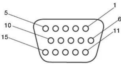
Mini D-SUB 15P
3) RS-232C Input (D-SUB 9P)
| Pin No. | Name |
| 1 | Connected to 7 & 8 |
| 2 | RXD |
| 3 | TXD |
| 4 | Connected to 6 |
| 5 | GND |
| 6 | Connected to 4 |
| 7 | Connected to 1 & 8 |
| 8 | Connected to 1 & 7 |
| 9 | NC |
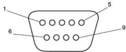
D-SUB 9P
2) Digital RGB Input (DVI-D) DVI
| 1 | TX2- 9 TX1- 17 TX0- | ||||
| 2 | TX2+ 10 TX1+ 18 TX0+ | ||||
| 3 | Shield (TX2/TX4) 11 Shield (TX1/TX3) 19 Shield (TXP/TX5) | ||||
| 4 | N C 1 2 N C 2 0 N C | ||||
| 5 | N C 1 3 N C 2 1 N C | ||||
| 6 | DDC-Serial Clock 14 +5 power 22 Shield (TXC) | ||||
| 7 | DDC-Serial Data 15 Ground (+5V) 23 TXC+ | ||||
| 8 | NC 16 Hot Plug Detect 24 TXC- | ||||
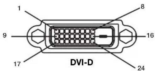
American National Standard for Human Factors Engineering of Visual Display Terminal Workstations ANSI-HFS Standard No. 100-1988
Veröffentlich vom: The Human Factors and Ergonomics Society P.O.Box 1369, Santa Monica, California 90406.
Canadian Department of Communications Compliance Statement
American National Standard for Human FactorsEngineering of Visual Display Terminal WorkstationsANSI-HFS Standard No. 100-1988
aio: The Human Factors and Ergonomics SocietyP.O.Box 1369, Santa Monica, California 90406.
Eepyoioei to eovosD.
Enotpeeoi npoyovevo evov oevov OSD.
Ia ovvdsoc Y/Cb/Cr, xpnooonote tic vnooxc DVD/ HD1 n DVD/HD2.
American National Standard for Human Factors Engineering of Visual Display Terminal Workstations ANSI-HFS Standard No.100-1988
Publicado por: The Human Factors and Ergonomics Society C.P. 1369, Santa Monica, California 90406.
Limpiar el Panel
American National Standard for Human Factors Engineering of Visual Display Terminal Workstations ANSI-HFS Standard No. 100-1988
Publié par:
The Human Factors and Ergonomics Society P.O.Box 1369, Santa Monica, California 90406.
8) DISPLAY Active/désactive I'OSD.
American National Standard for Human Factors Engineering of Visual Display Terminal Workstations ANSI-HFS Standard No.100-1988
Publicicato da: The Human Factors and Ergonomics Society P.O.Box 1369, Santa Monica, California 90406.
American National Standard for Human Factors Engineering of Visual Display Terminal Workstations ANSI-HFS No 100-1988
OIIy6IHKoBaHo: The Human Factors and Ergonomics Society P.O.Box 1369, Santa Monica, California 90406.
Ounstka nHaHeJI
- Pp3aP83HeHHn HaneHn nn cKoIIeHHn Ha He nIbIIOCTOPOxHO IpOTpuTe ee MAnKO TKAHbO.
He Tpnte IaHaeIb rpy6bIMMaTePmaIaMn.
He IaBnTe Ha IOBepxHocTb.
He nIOJIb3yIte YnCTTae cpeCTBO OA.Ipn erO IcIOJIb3OBAHm MOKHO IOBpeNTb NIN O6ecIeBETNb IOBepXHOCTb.
Ounstka Kopnyca
OTKIOUHTNEICTOCHNIKITNAHIA.
- Octopokho IIpoTpIte KopIyc MArKoT KaHbI.
TO6bO uHCTnTB KOpIyc, CMOUHTe TKAHb B BOte C HeITpaJIbHbIM MOIOIHMMpeIcTBOM, IPOTpNTe KOpIyc, a 3aTeM eIIe pa3 IIPOTpTE erO cyXoN TKAHbIO.
IIIPIMEYAHNE. IIOBepxHocTB KOpIyCa cocToNT n3 IIaCTMaCCbI pa3INuHbIX TNIIOB. HE BbIIOJIHnTe OUnCTKy c IIOMOIIbIO 6eH3OIOBOrO paCTBOPHTeJI, IeIIOUHO rO MOIOIeO cpeICTBa, MOIOIeTO cpeICTBa CO CInPTOM, ONUCTeJIe IIN CTeKOI, BOCKA, IIOJINPOJI, MBIIBHOrO IIOPOIIKA ININ INHCtNcIHNO HO BeIecTBA. B TeueHne IINTEJIbHOrO IEPNoDA BPeMeHN Pe3HnA ININ BUNHI He IOJIKHb KOHTaKTHPOBaTb C KOpIycom. TaKeI TEIIbIKNKOcTeI ININ MaTePnaIOB MOrYT INPBecTI K IOPYe, IOTpeCKNBANIO ININ OTcIAaIBAHNO KpacKn.
OuNCTKA BEHTNJRAUHOHBIX OTBEPCTNI
OuHuaTe BeHTNIAIOHHBie 06IaCTn Ila3MeHHORo MOHTopacIOMOIBIO IIbIEcOCa CMrKoI ΜeTKoI.
- IяобспeyeHHI npaBnIbHoi BeHTHJIuINN BblIOJIHЯTe OYNCTKy BEHTHJIIOHOHBIX O6laCTeKakJbI MeCJI. B 3aBNCIMoCTn OT cpeJIb, B KOTopoI yCTaHOBJe HIIa3MeHHbI MOHITOp, OYNCTKy MoKeT IOTpe6OBAtbcra BblIOJIHrTa 60JIee YAcTo.
IpeodotBpaueHne NOBJeHn IIN CHNXeHne 3oOpeKta OCTaToCHoro n3ObpaXeHn
Takke KaK IIIO6bIe MOHHTOpbIc fOocOphbIM NOKpbITHeM IIN IpyTne Ra30pa3PnHbIe INCIIJIeN, B IIIA3MeHHbIX MOHHTopax Ipi ONpeJeHbIX BO3HNKaET 3ΦΦeKT OCTaTOUHO rIOo6paKeHm. HeKOTOpbIe ycIOBn I KcIIyatauH, HApnPmep OTO6paKeHne cTaTNueCKORO IIO6paKeHm B TeueHne IPOIoJKNTEJBHO rIpOMeKyTKa BpeMeH, MOrTy IpiNBecTNI K BO3HNKHOBeHNO 3ΦΦeKT aOCTaTOUHO rIOIO6paKeHm, eCIn He IpeIIPnHtBi COOTBeTCTByIOUIIme MePb IpeIOCTOPOXHOCTN.IIra 3aIHTb IIIA3MeHHO MOHHTopa OT 3ΦΦeKTa OCTaTOUHO IIO6paKeHm co6IOJaTe CNeIyIOUIne IHCTpyKIIIN n peKOMeHndaIIN:
IIpn HcIOJIb3OBAHm MOHITopa c KOMIbIbTePOM BcerJa BKIOUaIte Ha KOMIbIbTepe 3KpaHHyIO 3actaKy.
IIO BO3MOXHOCTN BOCIIPOUN3BOJNTe IBNIraIOJIeecn 306paKeHne.
BpeMOT BpeMeHN N3MeHnTe IIOIOKeHne 3KpaHHOro MeHIO.
Iocne HcIOJIb3OBaHHaMOHHTopa BcerJa BbIKIOuayTeero.
YMeHbWeHne BepoTHocTn BO3HNKHOBeHnja 0OpeKTa OCTaToCHoro n3O6paXeHn npI npoJxKeIbHOM NcNoJIb3OBaHn
YMeHbIInTe yPoBeHb JPKoCTn KOKHTpaCTHO MIMHMaJIbHOI OTMeTKN, IIpN KOtOpO N306paXeHne OCTaETcA YeTKM.
- OTo6paKaaIte MHOIOUBeTHbIe N3O6paKeHnco MHoKecTBOM OTTeHKOB (HaIIpIMep,ΦOTOrpaΦHn HnΦOTOnIOo6HbIe N3O6paKeHn).
Co3aIte H3o6paXeHHe c MHNMaJIbHOJ KOHTpactHOCTbIO MeKJy CBETbIMN TEHMbIMN 06laCTaMn. IIO BO3MOKHOCTN NIOJIb3yTe DOIOJIHNTeJIbHBe IIN NaCTeJIbHBe IIBeta.
CTapaTecb He OTo6paKaTaBc H3o6paKeHn CHe6OblIMKoINHeCTBOMIIBeTOB NYeTKO BbPaKaHeHHbIMrpaHNiAmM MeKJy IBeTaMn.
3ByKn, BO3HnKaIOuIne npna paOte MOHITopa
IIaHeIb IIa3MeHHOro MOHITopa COCTOHT I3 IIKceIOB BbICOKOI IOITHOCTH, KOTOpBIE H3JIyauOT CBET B COOTBeTCBN CIOJyuaeMbIM BNDeocnIHAlAMN. IIO3OMy Ipr pa6ote IIa3MeHHORo MOHITopa MOJKHO yCbIIaTb JyKKaHne NINrIgHeNe. IMeTe B BuNy, YTO yBeIInuHm TEMInepaTpybI IIa3MeHHORo MOHITopa CKOPoCTb BpaIeHnOxIAkJaIOIero BeHTnIaTopa yBeIInuHBaetc. B TaKHe MOpEHbI cIbIeH IIyM IbnrTaTeJI.
IIIPIMEYAHHE: IapaHTnHe paacIPOcTpaHReTcHa.
3ΦΦeKTOCTaTOHORIO3O6paKeHH
3ByKn,NCnYcKaemBie NaHeIbIO.
PiMepbl:ABnIaTeIb
BeHTnIaTopaAeKeKTPueCKNe IyMbI,
rJdeHne BJIeKTPueCKNX eIINX/
KyKKaHne CTeKJIaHHoIIaHeIiN.
UCIOBNA 3KCPNYATAUIN
TeMnepaTpya HbAaKHOCTb OKpyKaIOIe CpeBb:OT 0^ I0 +40^ (OT +32^ IO +104^ ;OTHOCTbIbHbAH BIAKHOCTb BO3JyXa MeHee 80% (OTBepCTIg IJIaXKeHnHE 3a6IOKINPOBaHb).He pa3MeuaIte YcTPOIcTBo B IIOXO BeHTNIMPyEMOI O6JIaCTH, B MecTaX C BBICOKOI BIAKHOCTbIO IIN IIIOI IIpRMBIM COIIHeuHHBM INYUAMN (IOI CNIBHBIM NCKYCCTBeHHBM OCBeIeHNEM)
PPEyPExKdEHN
He IINIOB0AHH B MaIIHHHOM 3aJIe corIaCHO cTAnapry Protection of Electronic Computer/Data Processing Equipment ANSI/NFPA 75 (3aIIHTa 3JIeKTOHHO BbIHCINTEbHO O6OpyIOBAHn/ 06OpYIOBAHnO 6pa6OTKn dAHhIx).
IIPIMEVAHNE: NcnoJIb3yIte 3KpaHnPOBaHHk Ka6eJIb BuJeOCHHaJa ot 15-KoHTaKTHOpa3BeMa mini D-SUB K 15-KoHTaKTHomypa3BeMy mini D-SUB c feppntOBBMncepJeHHKaMn Ha o6oNX KOHcaX (He BXODIT B KOMIIeKT IocTaBKN).
IcnoJb3OBaHne DOONHHTeJIbHbIX CTOeK/ KpenJeHn
MoKHO yCTaHOBnTB DOIOHHTeBHyIO CTOnKy nn KpeIneHne.
KorIa IIaHInpyTeTcYCTaHOBnTb CToIKy IIN KpeIIeHne,a yCTPOiCTBO IIpN 3OTM HAIIpaBJIeHO IINIEBOI CTPOHOH BHN3 (Pnc.1), BO I36ekaHne IOBpeKJdeHn EKpaHa O63aTeJIbHO IIOXHTe IIOI Hero 3aIITbI JNCT (IeHOJIaCTOBH IINCT, B KOTOpBb 6bIIO 3aBePhyTO yCTPOiCTBO).
JaHHoe yctpoiCTBO IOJIKHIO HCIOJIb3OBAITBCa CO cTOnKoN mN KpeIeHem KaKOrO-JIN60 TnIIa. JaHHoe ycTPOiCTBO He IpeHa3HaueHIO JINr HCIOJIb3OBAHn8 6e3 dIOIOHNTEJbHOIIOpbl.
IIO6epeHn npaBnBHO yCTAHOBKn KpeIIHeHn peKomeHnyerC O6paNTbC K 06yehHOMy ABTOIN3OBAHOMy paNPOcTpaHNTeIO.
Ipn Hec6bHIOJeHH IPOueyyp IpaBnIbHOKpeIIeHH BO3MOxHO IOBpeKeHHe yCTpoIcTBa IIINIOJyHeHtPaBMBy YcTaHOuNkOM.
- FapaHTnI N3eJIINr He pacInpocTpaHReTcHa HIOBpeKHe, Ipon30WeiWee B pe3yIbTaTe HEIIpaBnIbHOYcTaHOBKn.
BHIMAHNE.
IINBIIIOHHeHHyCTaHOBKn CNeIyITe HNCTpyKIIIM, KOtOpBle IpiNlraIOTc K CTOnKe NnKpeIeHHIO. IVIOJIb3yIte TOJIbKO yCTpOJCTBa, peKOMeHIOBAHHbIE pON3BOIDTeEM.
- Pn yctaHOBKe cToKu Hn KpeIeHnO63aTe/ho pacIOJoxNte yCTpoIcTBO Ha KpeIKoN uYCTOuHBOI IOBepXHOCTn, CIOOCbHO BbIePkaTB Bec yCTPOINCTBA, HAIIpIMep IOny Hn IIPOOHOM cToIe.
-ДяуCTaHOBKNIICIOJIb3yIteyKa3aHHHbIe3aKIMbl.
Bo 36ekAHHe OINPOKmBbAHn HnPiAeHn yctpoiCTBa BbIOJHnTe Heo6xoIMMbIe JeICTBn.
Mecro yctaHOBKn
IOTONOK nCTeHa IOnKnBb 6bTb IOcTaOuH0 KpeKNMn, YTO6b BbIepKaTaMoHToP IN PpHaJIeXHOCTn IIN KpeIIeHH.
HEyctaHaBnBaIte ycTpoiCTBO B MecTx, rIe erO MOryt 3aIeTb IBebp HIN BOPOTa.
HEyCTaHaBnBaIteYcTpoIcTBO B MecTaX,IIe Ha HrO 6yTe BO3JeIcTBoBaT CmIbHa Bn6paIuN I IIbIb.
HEyctaHaBnBaIte yctpoIcTBO6H3MeCt,1e OCHOBHOH NCTOUYHK INTaHNAIOXoNT K 3JaHNIO.
HEyctaHaBnBaIte yCTpoNcTBO B MecTaX,Te Ha HEM NnHa KpeIIeHm MOrY IOBnCHyt IIOuN.
IIpyuCTaHOBKe BIIkaΦIINyIy6JIeHne (KaK, HApnpMep,BCTHe) IINo oecneueHHn HaIeKaIeBEHTNIIcHm MEJky CTeHOH N MOHITOPOM OCTaBBtepacctOAHnHe He MeHee 2IOHMOB (50 MM) (Pnc.2).
-06ecIeBteIOCTaOHTHyIOBEHTNIIuHIO NIKOHIMIOHINPOBAHNA BO3yxa BOKpyr MOHITOPa,TO6bTeIIOOTyCTpOINCTBaIKpeHIEHNpaCCENBAIOCB DOJKNHbIM 06pa3OM.
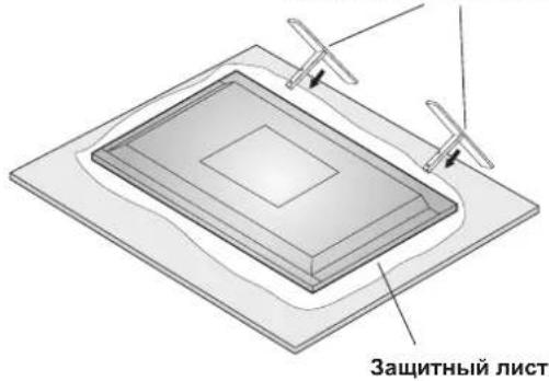
Pnc.1
DOnOHHTeJIbHaB BepTnKaJIbHaCTOka DnKpEnneHn Ha CTone
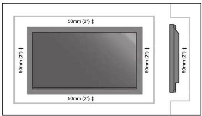
Pnc.2
YctaHOBka Ha IIOToJIke
Y6eNTecb,TOIOTONOKIOCTaTOHIOIPOuHbI, YTO6bBbIEpKaTb Bec yCTPOJCTBaN KpeIIeHnB TceEHNE IINTEJIbHO BPEMeH N pN 3eMItePaceHnx, BH3aIIbIX BN6pauiN INPOuNX BHeIHINX BO3JECTBHX.
Y6eHNTecb, YTO yCTpOHTBO KpeHNTcHa IPOuHOI KOHCTpyKIIIN B IOTOLKe, HApPIMep Ha OIOpHOI 6aJIke. 3aKpeHNTe MOHITOP C IMOOIBIO 6oTIOB, IpyKINHBIX N OOBYHBx IIaIbIg RaIKN.
HEOCYIeCTBIAIte YcTAIOBky B MeCtax 6e3 BHyTpeHHeOIIOPHOKOHCTpyKuHN. HE NcIOJIb3yIe IJIa KpeIIeHnI IUPyIb IIN aHKePHeIe BNHTbI. HE yCTaHaBIABaIte yCTpoIcTBo Ha OTJeIKy IIN CBnCaIOIIne KpeIIeHnI.
O6cIyJxNBAHne
- IepnoJnueckn npOBepaTe ocna6Hne BuHTbI, 1eH, NCKpNBHeHn Hn npTyHe npO6HeMb, KOtOpBle MOyT IpOn30nTc KpeIIHeHem. Pn o6HapyKeHHn np6HeMb 6paTntEcK KBaIHnHnnpoBaHHOMy pa60THNKy nI npOBeEHn O6ClyKuBAHHa.
PeyraHPOIPOBepaHTe MeTO yCTaHOBKn Ha IIpHaKINOBpeKdEHHN HIN Ocna6eBaHHN, KOToPbIE MOryTIIpon3OHTn CO BpeMeHem.
IIpnMOntaKeHa cTeHy mIINIOToJIOK NMeIte BBNdy cIeIyIOoee
IIpn HcnoIb3OBAHn HpHaIeXHocTe n MoHTaKa, KOTOpBHe He 6blnn OIO6peHb KOMnAHneh NEC,y6eINTecb, YTO OHN COOTBeTCTBYOT MeToy KpeJIeHHa, COBmecTNMOy c VESA (FDMly1).
KOMIIAHNA NEC HAcToTeIbHO peKOMeHpyET NIOJIb3OBaTb BnHTb M8 (16 MM + TOIIINHa KPOHIteHa). IIpN HCIOJIb3OBaHNBnHTOB, KOTOpBe IINHHee 16 MM, IIPOBepTe Iy6Hy OTBepCTHA (peKOMeHIOBaHIOe ycHIne: 1125 - 1375 H.CM). KomIIaHNA NEC peKOMeHpyET INHTepfeiCbI KpeIIeHHa, KOtOpBie COOTBeTCTBYIOT CTAHApTy UL1678 (CeBepHa AmePKa).
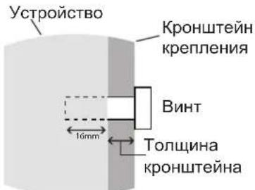
HnHa BnHTa DoJnxHa paBnTbCra
Iy6nHe OTBepCTna (16 MM) +
TONuHa KPOHnTeHa KpePnHeHn.
IpiNcIOJIb3OBAHNNIINCIIIeB KHNKHOJOpNEHTaUNMOHHTOP BKNIOHTe YCTaHOBNTe B 3KpaHHOM MeH0ONIIY2IpyHKTa COOLING FAN 3HaueHHe BKJI.

Yklaika ka6eien
Iyno6Hoy kJIAKn Ka6eNe IcIOB3yTe 3aKIMbI,
IpeHa3HaueHHBe IyCB3KN CeTeBOrO IHypa C Ka6eJIIMN
CnHaHa n ayIOkA6eJIIMN B 3aHHe yactn dncIIe.
KpeIIeHHe Ka6eIbHbIX 3aXIMOB
1.ПИКРЕПНТеKa6eJIbHbIe3aKIMbI KДиCIIJIeO.BCTaBBTe Kapa6nH 3aKIMBa OTBepCTHe Ha 3aJIHeYacTnДиCIIJIe. IIN4 Ka6eJIbHbIX 3aKIMOB Ha yCTpOJCTBe IMeETc4 OTBepCTnI.
2.ПocIe paCIOLOXKeHnKa6eBbHOrO 3aKHMa Ha nCIIpe
06MOTaIte KOHeI BOKpyr Ka6eJIe.BCTaBBTe KOHeI 3aKHMa
B OTBcPCTne pAOM c Kapa6uHOM.HaTHnBaIte, NOka
Ka6eJIH He CTAHYTCJ.
3aKMBI IIpeHa3HaueHbIIINΦHKcaUN Ha MeCTe. IocJIyCTaHOBKn 3aKMOB INCIOKHOO BHyTb.
3. Ka6eHIMoKHOIPOIOXHTCINPABa HIN CNEBa OTRaKHMa.
IIaCKpeHHeHnKa6eHIN BcEHNHHe NcNtB3yInTe
CTA8Kn.Y6eHITecb,HTO Ka6eHIN yepKNaOTcH
HOJTHOCbR.
OToeHHeHne3aXnMOB
C NOMOIIbIO IIOCKORY6IeB NOBepHInTe 3aJHM Ha 90
IpaIycOB IN BbITAHInTe erO. C TeueHNem BpeMeHN 3aJKM
MOKeT OcIa6HyTB IN IIpN IN3BHeEHn ERO MOXHO
IOBpeINrB.
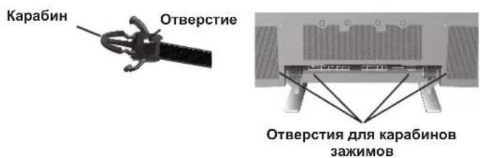

OpneHTaun
IIpn NcIOJIb3OBaHmI INCIIeB KHNKHOJOpHErTaUNMOHHTOP Heo6XOIMMO IOBePHyTB IIO YacBOO BCTpeJIKeTak, YTO6bI IeBaI CTopoHa IepMeecTNlAcB BBepx,aCBETOnIOHbI INHINKaTOp 6bl paONIOKeH BN3y.IIpn 3TOM OeCeHbAeTCn HAJIeKaUAn BeHTNIAuNHyBEJIINBaETcCpOK CNYK6bl MOHtOpA.IIpn HEINPAHbHOI BEHTNIAUIN CpOK CNYK6bl MOHtOpaMOKeT COKpaTNTbcra.
IcnoIb3ObaHne IyIbTa InCTaHIIOHHO yIpaBHeHna
YcTaHOBtSe 6aTapeKIN B NytB TnCTaHIOHHO YIpaBHeHn.
IITaHHe NylbTa IInCTaHIOHOHorO ynpaBHeHH
ocuieCTBJIeTcra OTe 6atapeek AA. YTo6bYcTaHOBHTb
HIN 3aMeHtB 6atapeKn, BblIOJIHTe yka3aHHbIe HNKe
JeIcTBnI.
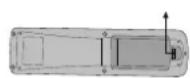
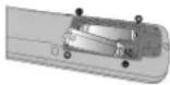
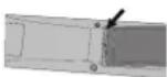
A. HaKMInTe n CdBnHbTe KpbIbKy, Yo6bI OTKpbITb ee.
B. YCTaHOBnTe 6aTapeeKn B COOTBeTcTBn C o6O3HaueHnMaN (+) n (-) BHyTpN KOpNyca.
C. YcTaHOBnTe KpbIIHKy Ha MeCTo.
BHIMAHHE. HenpaBnIbHoe nCIOJIb3OBAHne 6aTaapeek MoKeT IIpNBecTN K yTeYkAM NIN B3pyIBy. KomIIaHnNE CPeKOMeHJyET NCIOJIb3OBAtB 6aTapeKN CJeIyUOIMM 06pa3OM.
- YctaHOBNTe 6aTapeKn pa3Mepa AA TaK, YTO6bI 3HaKn (+) n (-) Ha KaKIOH 6aTapeKe COBIIaJIn CO 3HaKaAMn (+) n (-) B 6aTapeHOM OTceKe.
He nCIOJIb3yIte 6aTapeKn pa3HbIX MAPoK.
He nIOJIb3yIte CTapBIE HOBIIe 6aTapeKIN, a TaKKe 6aTapeIKn pa3HbIX MapOK. IIpn 3tOM MOKeT cokpaTHTbcra cPOK cnYk6bl 6aTapeek ININ IpOu30iTN yTeYka 3JIeKTKpoNTa.
Bo n36ekahne yTeuKN 3eKtpoNTa B6aTapeHOM oTceKe cpa3y BbHbTe ceBHNe 6aTapeKn.
HeIOTpaHbAitcBIOJIeKtpoITa,IOCKOJIbKy OH MOKeT IOBpeINTb KOKy.
He poHnTe IyIbT InCTaHIOHOHOrO yIpaBIEHNn I nCIOJIb3yIte ero IO Ha3HaueHIO. - IIyIbT IINCTaHIOHHO yIIpaBHeHNe He OJKeH IIpOMOKaTB. EcIn Ha IIyIbT INCTaHIOHHO yIIpaBHeHNe IIOHaTe BODa, cpa3y BbITpuTe erO Hacyxo.
- I36eraIte Ype3MepHOro TeIIaN BlaJxHocTn.
He BbIKnIbIBaIte 6aTaapeKINBoroHb. - Pn yTIN3aUNN NCIOIb3OBAHHBX 6aTapeek CNeIyTe IpaBNTeJIbCTBEHHBM IOCTaHOBIEHNIM NIN O6IeCTBEHHBM IpaBNIaM 3aIHTbOkpyKaIOIeCpeNb, KOToPbIe DeNCTByOT B CTpaHe/O6NaCTN.
- Pn 3aMeHe NIOJIb3yIe ToJIbKO O6bUHbIe HeIpe3apJkaEMbIe IeIoUHbIe IIN MapraHcEbbIe 6aTapeKn.
- Pn HnepaBnHbHOy yCTaHOBKe 6aTaapeek cyIecTByeT OIIacHOCTb B3pbBa.
Pa6ouH mHaIa3OH nIyIbTa IINCTaHIOHOHorO yIpaBHeHH
IpiHaKaTHN KHOIOK HAnpaBJIaTe BepXHIOU qACTb
IIyIbTa IInCTaHIOOHORO yIpaBJIeHnHa DaTtNK
MOHTOPa.IyIbT IInCTaHIOOHORO yIpaBJIeHn MOJHO
HCIOJIb3OBaTB Ha MaKcIMaJIbHOMpacCToHHN 7M/23 yTa
OT IpeJHeY qACTn MOHTOPa.OT IpeJHeY qACTn DaTtNKa
IINCTaHIOOHORO yIpaBJIeHn IIa3MeHHORO MOHTOPa.
MaKcIMaJIbHbIyTOI IO TOpH3OHTaII N BePtHKaII INp
HCIOJIb3OBaHHN IIyIbTa IInCTaHIOOHORO yIpaBJIeHn Ha
pacCToHHN 3,5 M/11,5 yTa coCTaBJIaET 30 rpaIycob.
BHIMAHHE
IyIbT IInCTaHIOHO ynpaBHeHn MoKeT He pa6oTaTb
IIpi IIOIaHn Ha DaTynK IIa3MeHOrO MOHTopa
IpyMbIX COJIHeYbIX Iyuee HIN 60JIbHIrO KOJIneCTBa
CBeta, a TaKke Ipi HaJIuHn IIpepaI.
O6paIeHHe c IyIbTOM IINCTaHIOHOHor OIpaBHeHH
OTkpBaIte IyIbT IInCTaHIOHHORO yIpaBHeHnra ToIbKO
IIra YcTaHOBKn 6aTapeek. He IOnyckaIte IOnaHaHnra Ha
IIyIbT IInCTaHIOHHORo yIpaBHeHnRA BoIbI INn IpyToR
KINkoCTn. EcIn HA IIyIbT IInCTaHIOHHORO yIpaBHeHnra
IIponaTe BOJa, cpa3y BbITpNte erO hAcYxo.
N36eraIte BO3JeCTBnra TeIINa n Iapa.
IIIPIMEUAHNE. EcnnIyIbT IINCTaHIOHOHORO ynpabJIeHHn He IIaHpyETcN HCIOJIb3OBaTb B TeueHne IInTeJIbHOrO cPOKa, BbIHbTe 6aTapeKn.
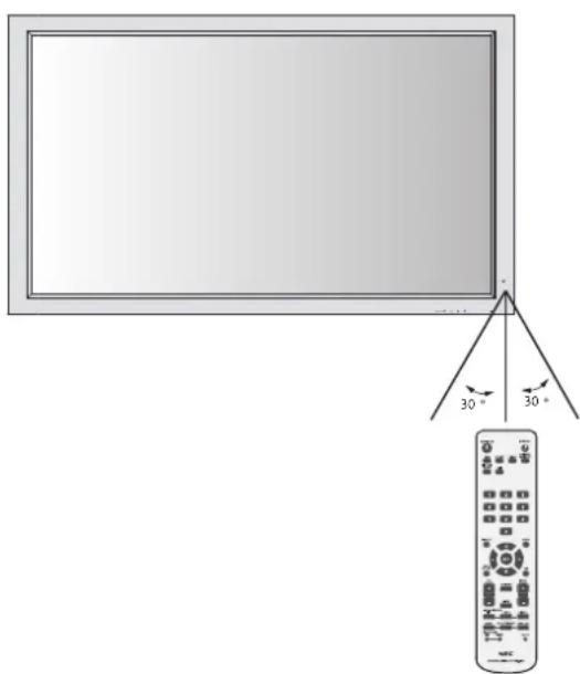
Ha3BaHnI DeTaJIeN I ΦyHKcIIN
Panaelb ynpabJeHnA
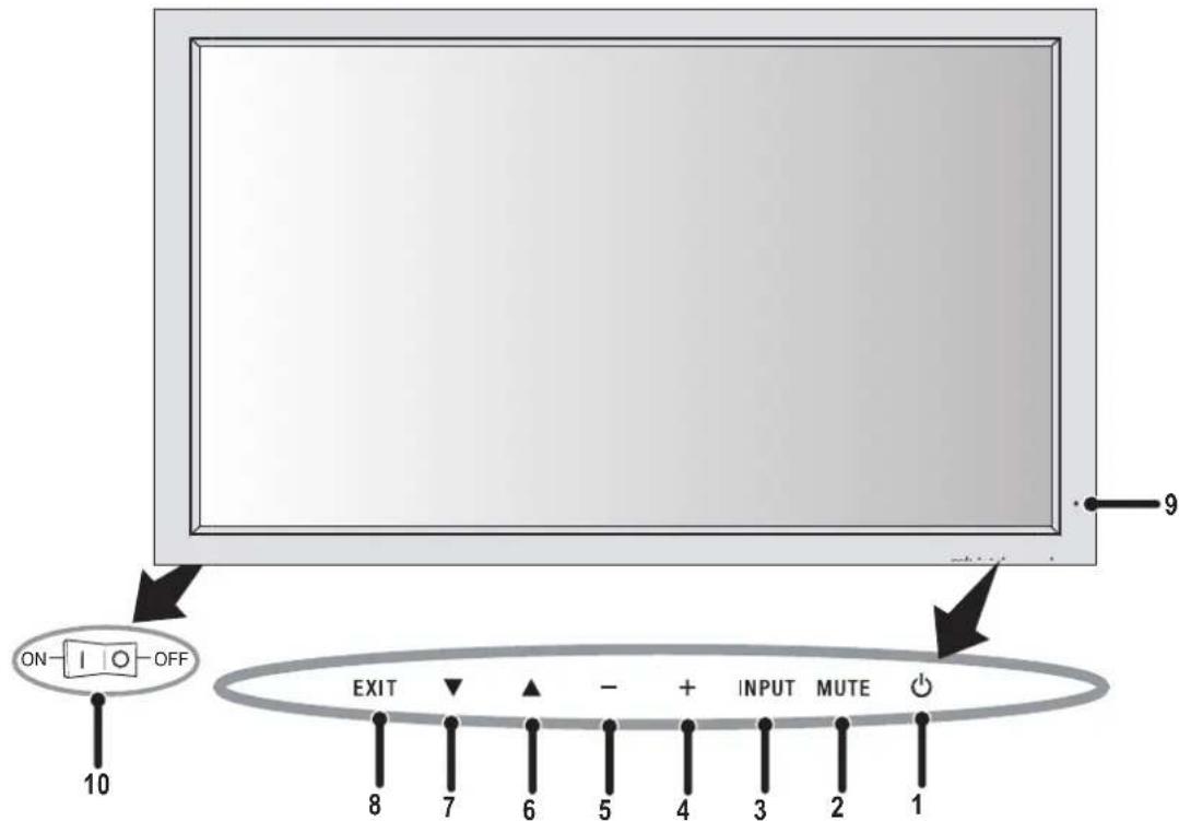
1) IITAHNE
BkHIOUeHHe IITaHnI/epexoB BpeKIM OxuHaHnI.
2) MUTE (OTKJIIOUQEHN3BYKA)
BkJIOueHHe/ByKJIOueHHe 3Byka.
3) BXOД
IpekeKIOUeHHe NCTOuHnKOB BXoHOrO CnTHaJa.
JenCTbyET KAKKHOONKA YCTAHOBKA B 3KpaHHOM MeHIO.
4) IJIIOC (+)
YBeIuHHeN3HaueHnI npaMeTpaB 3KpaHHOM MeHIO.
5) MHHYC (-)
YMeHbIeHHe 3HaueHnI IapaMeTp a B 3KpaHHOM MeHIO.
6) BBEPX (▲)
YBeJIuHHe yPoBHa rPOMKoCTn,ecIIN 3KpaHHoe MeHO BbIKIOUcHo.
IpepeMeHHe O6bactn BBepx IyBb6opa HactpaBaEMO IpaMaTePb AKpaHHOM MeIO.
7) BHN3 (V)
YMeHbIeHne yPoBnI rPOMKoCTn,ecn3KpaHHoe MeHIO BIKIOyeHO.
IepemeeHHe NoBnBn3 nBb6opa HactpaunBaemoro npaMeTp a BkpaHHOM MeHO.
8) BbIXOJI
BxOJ B 3KpaHHOe MeHIO,ecn OH OBO bIKIooHeO.
BbIXoI N3 OTo6paKaemOro B HAcToIeE BpeM MeHIO Ha MeHIO IpeIbIyIeIero YpOBHr BkPaHHOM MeHIO.
9)IaTnK IInCTaHIOHOHorO ynpabHeHn HnDnKaTop nHTAH
IpiHcHHaIa IIpi NcIOJIb3OBAHm6ecIpOBOHOIro IyIbTaIINCTAHnOHHOYnpAbeHH. EcIM MOHTOP BKIOUeH,ROPIT 3eJIeHbIM ΒBeTOM.EcIM MOHTOp HaxODITcBpeKHM OxNdaHH,ROPIT KpachbIM ΒBeTOM. EcIM MOHTOp HaxODITcBpeKHM YIP.PINTAHHE,ROPIT KeITbIM ΒBeTOM.
Ecln HNtKaTOp NTaHnMutaet KpaChbIM ZBeTOM, MOHTOPOM 6hApyKeHa HeNCIpaBHOCTb. BcIyae BO3HNKHOBeHn HncIpaBHOCTn O6paTNTecb K KBaIIΦuINpOBaHHOMy pa6OTHky.
10) IaBbI IepeKIOuATEIb IITAHIN
IpeeknooyateBnBkHooeyHn/BbIKHOuyHn HnTaHn.
OtcytctByeT n306paKeHne
Ka6eBnBnEocnHanaIOJKeH 6bTb NpaBnBHO IOKIOUeH KIIaTe IUCIIIE/KOMIbIbOtepa.
IIIATAIINCIIIEIIOJIKHA6bITbIpaBNIbHOyCTAHOBJIeHa B pa3bEm.
- IpeekIIOuateIb IIITaHnHa InepeIHeI NaHeII IN IpeekIIOUateIb IIITaHnKOMIIbItepa IOnIKHbI HxOIMTbcB B IIOJKeHH "BKJI".
Y6eNTecb,TOHaHCIOIbayEmoIIaTeIINcIIeHnCInCTEMBb6paHIOIIepKNaBaEMbIpeKM.(JIIM3MeHHeHHIpaHueCKOTopeKMaO6paTNTecbKpyKOBOCTByIOJIb3OBaTeNIIaTHINcIIeHnCInCTeMbI.)
IPOBepbTe COBmecTMOCTb MOHHTOpa NIIATy DNCHN, a TaKKe peKOMeHNyEMIe HAcTpoiKN.
IIpoBepbTe, HIEHpeHHTINKa6eJIb HHeT IN3aIaBunx KOHTAKTOB Bero p3beMe.
KhoIIka nHTaHnHa He pa6oTaet
- OToCoeHHTe ceTeBoi HHP MoHHTopa H3 po3EKn CeTH IepemEHORo TOKa, YTO6bI BBIKHOHTb MOHHTOp N C6pocHTb HaCTpoHN.
3006paeHH
IMeTe BBnHy, TTO B IINa3MeHHoTexHOIOH cyueCTByeT Oco6eHHocb, H3bHaemra 300EKTOM octaTOHOrO N3o6paKeHn. 300EKT 3AKIOUyaeTcB TOM, YTO Ha 3KpaHe OCTaETcA OCTaTOOHoe N3o6paKeHne IIpeDbluyeep KAPTHKN. BOTINuHEOT CRT-MoHTOpOB, 300EKT OCTaTOHOrO N3o6paKeHn B IINa3MeHHbIX MOHTOpax He ABInETcN IOCTOAHBM, OINaKO CNEyET N36eRtB OTO6paKeHne OINHO NTOJKe N3o6paKeHn B TeueHHe DIOrTO BpEmHn. IIN yCtPAHeHN 300EKTa OCTaTOHOrO N3o6paKeHn BIKIOHTe MOHTOp HA BpEM, PAHoe BpEmHn OTO6paKeHn IIPEbIyIero N3o6paKeHn. HApnPmEp, ecIn N3o6paKeHne He MeHIIOCb HA MOHTOpbe TteueHHe Yaca, IN B pe3yIbTaTe OCTaETcN OCTaTOOHoe N3o6paKeHne, BIKIOHTe MOHTOp HA qac, YTO6bI OHIO HCye3IO.
IIPIMEYAHNE. KopnpopuaNE NEC DISPLAY SOLUTIONS. peKOMeHnyET BOCnpon3BedeHne NOBnKHOrO N3o6paKeHHN HNCIOJIb3OBaHHe 3KpaHHo3acTaBKn Yepe3 paBHie IpOMEkyTkn BpeMeHN DnBCEX INCIIeEB BCKNi pa3, KOrJa INcIIIEe 6e3dEChByet. PeKOMeHnyETc TaKke BbIKIOuATb MOHTOP,ecn He NCIOJIb3yETcJ.
H3o6paKeHne HeyctOuHBOe, HecokycpOBaHHoe HmCMeIaTcra
Ka6eBnIeocnHaJaIOJIKeH 6bITb HAJIeKaIIMo6pa3OM coeINHeCIIa3MeHHbIM MOHTOpOM, KOMIIbIOTepOM IIN npYHM yCTPOINCTBOM BBOJa.
IcnoB3yTe cpeCTBa ynpaBHeHn 3KpaHHbIM MeHIO IIA NaCTPOIN KΦOKycuPBOKn H3O6paKeHn HHTeM yBeJIuYeHn Hm YMeHbWeHn FAs3b CnHXpOH3aHn. PIn N3MeHHeHn peKnMa pa60t b nCIIe MoKet HOTpe6OBaTbC HOBTOHO HAcPToNTb IapamEtpy H3O6paKeHn 3KpaHHoro MEHO.
IPOBepbTe COBMeCTHMOCTb MOHITOpa HIIaTb IINCIIIEe,a TaKKe peKOMeHNyEMHe CnHaJIb CnHXPOHN3aUN.
I3o6paJkeHne KOMnHOeTHTO CnTHaJa
3eHEHOBATOIBeta
- PioBepbTe, Bb6paH nn BXoHn pa3bEm DVD/HD.
He ropntCBETOIOHOHBn HnHkKaTOp (HN 3eIeHbIM, HN KpaChbIM uBeTOM)
ΓIaBbH IIpeEeKIOUaTeIb IIOJIKeH 6bITb yCTaHOBJEN B IIOIOKeHHe BKJI,a cTeEOBIIHHyp -IOIKIOUeyH.
KpacbI CBeTOIOHbI INHnKaTOP Ha MOHTope MNraet
BepoTHO, pOn30IeI c6oJ. CByKHTecb c 6IIHKaIIIM aBTOp30BaHHbM cepBnCHbM IeHTpOM KOpnpaUN NEC DISPLAY SOLUTIONS.
Pa3Mep H306paJKeHnHa IIncIIee HAcTpoEHIIpaBnIbHO
IcnoB3yutepeCTBaYnpaBHeHn3KpaHHbIM MeHIO yBeIeHnHn HmYMeHbIIeHnHTOROBTO 3HaYeHN CNHXPOHN3aHnN.
Y6eNTecb,TOHaHCIOIb3yEmoMIIaTe DnCIIeR HIN CnCTeMb Bb6paH IOJIpeKNaBemb peKm.(JIN N3MeHnRAIpaHueCKOTopeKMaO6paTntEc b K pyKOBOCTBy NOIb3OBaTeNIIaTb IINcIIeR INN CnCTeMb.)
Bb6paHHe n3o6paJKeHne oTo6paKaetc HnPaBnIbHo
IVcnoB3yTe cnpaBky kpaHHoro MeHIO, YTO6bI BOHTN B MEHIO HOpMaUNn y6eJntecb, YTO BbIbpaHO COOTBeTCTByIOUee pa3peIIHeHne. B IpOTNBOM Cnyae BbIbepNTe IIpaBnBHOe pa3peIIHeHne.
OTcyTCTBHe 3Byka
IpoBepTe IpaBnIbHocTb IOKJIIOUeHHa6eJIa HHaMnKa.
IIpoBepbTe,HeOTKIOUoHEN3ByK.
IpoBepTe,He y6aBHeJH 3BYK IO MNHMMya. IIPIMEYAHHE.MoKHO BOCnPOUNBOJNTb 3BYK OT HCTOHHKa,OTNIHOROT BNDEOHCTOHHKa.
RS-232C He pa60tae
-ПоверпгураMuTe YCTAHOBKA B MeHIO OIIIN2.
IyIbT IInCTaHmOHHOro yIpaBleHnHe pa6oTaET
- Y6eIMTeCb, yTO 6aTapeKn BCTaJIeHb IIpaBnJIbHO.
-Поверпгдзарб6атapeек. - Y6eIITecb, TTO IIyIbT IINCTaHIOHHOYIpaBHeHH HAnpAbHeIIpMo HAJaTuNK MOHHTopa.
IIpoBepbTe He HaxoIHTcH IINIyIbT INCTaHIOHOHOrO ynpabHeHn BpeKMe NIEHTNkAuaN IyIbTa INCTaHIOHOHO ynpabHeHn.
IyIbT IINCTAHINHOYIIpaJIeHHe pa6oTaETIOI pIIMMn COJIeHbIMN LyaAMn IIpN NOHaAHN 60JIbIHO KOnIYeCTBa CBETA Ha IINCTAHINHOHH DaTHNK MOHITOPa. -
IIpoBepBe npaMetp N.K.IY.B MeHIO OIIINJ3.
-
Plazma Monitor
Uzaktan kumanda ve AA Pilleri
Guc kablosu - Kullanı Elkitabı (CD-ROM)
- Bavlangić Kilavuzu (Kagit/CD-ROM)
Ana Guc Dugmesi kapaig ve vidası
Kablo kelepçeleri
Içindekiler
American National Standard for Human Factors Engineering of Visual Display Terminal Workstations ANSI-HFS Standard No.100-1988
Yayinlayan:
The Human Factors and Ergonomics Society P.O.Box 1369, Santa Monica, California 90406.
Temizlik ve Panel
WEEE Mark (European Directive 2002/96/EC)
Within the European Union

EU-wide legislation, as implemented in each Member State, requires that waste electrical and electronic products carrying the mark (left) must be disposed of separately from normal household waste. This includes monitors and electrical accessories, such as signal cables or power cords. When you need to dispose of your NEC display products, please follow the guidance of your local authority, or ask the shop where you purchased the product, or if applicable, follow any agreements made between yourself and NEC. The mark on electrical and electronic products only applies to the current European Union Member States.
The mark on electrical and electronic products only applies to the current European Union Member States.
Outside the European Union
If you wish to dispose of used electrical and electronic products outside the European Union, please contact your local authority so as to comply with the correct disposal method.
Declaration of the Manufacturer
We hereby certify that the color monitor P426Y0, P506Y1 or P606Y2 is in compliance with Council Directive 73/23/EEC:
- EN 60950-1
and marked with

Council Directive 89/336/EEC:
EN 55022
EN 61000-3-2
EN 61000-3-3
— EN 55024
NEC Display Solutions Ltd.
4-13-23, Shibaura,
Minato-Ku
Tokyo 108-0023, Japan
DECLARATION OF CONFORMITY
Th is device complies with Part 15 of FCC Rules. Operation is subject to the following two conditions. (1) This device may not cause harmful interference, and (2) this device must accept any interference received, including interference that may cause undesired operation.
U.S. Responsible Party: NEC Display Solutions of America, Inc.
Address: 500 Park Blvd. Suite 1100
Itasca, IL 60143
Tel. No.: (630)467-3000
Type of Product: Computer Monitor
Equipment
Classificati on: Class B Peripheral
Model: PlasmaSync 42XP10 (P426Y0)
PlasmaSync 50XP10 (P506Y1)
PlasmaSync 60XP10 (P606Y2)

We hereby declare that the equipment specified above conforms to the technical standards as specified in the FCC Rules.
Windows is a registered trademark of Microsoft Corporation. NEC is a registered trademark of NEC Corporation. All other brands and product names are trademarks or registered trademarks of their respective owners.


- Table of Contents
- Read Before Operating Equipment.
- Additional Safety Information
- WARNING
- CAUTION
- Canadian Department of
- Communications Compliance Statement
- FCC Information
- Safety Precautions and Maintenance
- CORRECT PLACEMENT AND ADJUSTMENT OF THE MONITOR CAN REDUCE EYE, SHOULDER AND NECK FATIGUE. CHECK THE FOLLOWING WHEN POSITIONING THE MONITOR:
- Ergonomics
- Cleaning the Panel
- Cleaning the Cabinet
- CLEANING THE VENT HOLES
- To avoid or minimize image retention:
- To reduce the likelihood of image retention from long-term use:
- Plasma monitor driving sound
- OPERATING ENVIRONMENT
- Using Optional Stand/Mounts
- CAUTION:
- Mounting Location
- Mounting on Ceiling
- Maintenance
- Please note the following when mounting on wall or ceiling.
- Orientation
- Cable Management
- Using the Remote:
- Install the remote control batteries.
- Operating Range for the Remote Control
- Handling the Remote Control
- Terminal Panel
- Remote Control Functions
- 1) POWER ON/STANDBY
- 2)VIDEO
- 3) RGB
- 4) DVD/HD
- 5) PICTURE MODE
- 6) SIZE
- 7) KEYPAD
- 8) DISPLAY
- 9) ▲▼
- 10) AUTO SETUP
- 11)POINTER
- 12)VOLUME
- 13)SPLITSCREEN
- 14)REMOTEID
- 15) MENU
- 16)SET
- 17)-,+
- 18)EXIT
- 19)ZOOM
- 20)MUTE
- 21)SLEEP
- Part Names and Functions -continued
- POWER
- To turn the unit ON and OFF:
- DISPLAY
- DIGITAL ZOOM
- POINTER
- Main Power Switch Cover
- REMOTE CONTROL ID
- TO SET REMOTE CONTROL ID:
- TO USE REMOTE CONTROL ID MODE
- Remote Control ID Function
- On-Screen Display (OSD)
- Using the OSD
- Control Panel
- No picture
- Power Button does not respond
- Image persistence
- Image is unstable, unfocused or
- swimming is apparent
- Image of component signal is greenish
- LED on monitor is not lit
- (no green or red color can be seen)
- Red LED on monitor is blinking
- Display image is not sized properly
- Selected resolution is not displayed properly
- No Sound
- RS-232C does not work
- Remote Control does not work
- Specifications P42XP10
- Specifications P50XP10
- Specifications P6oXP10
- P42XP10 Supported Resolutions (PC)
- P42XP10 Supported Resolutions (Video)
- P50XP10 Supported Resolutions (PC)
- P50XP10 Supported Resolutions (Video)
- P6oXP10 Supported Resolutions (PC)
- P6oXP10 Supported Resolutions (Video)
- Pin Assignment
- Canadian Department of Communications Compliance Statement
- Limpiar el Panel
- Ounstka nHaHeJI
- Ounstka Kopnyca
- OuNCTKA BEHTNJRAUHOHBIX OTBEPCTNI
- IpeodotBpaueHne NOBJeHn IIN CHNXeHne 3oOpeKta OCTaToCHoro n3ObpaXeHn
- YMeHbWeHne BepoTHocTn BO3HNKHOBeHnja 0OpeKTa OCTaToCHoro n3O6paXeHn npI npoJxKeIbHOM NcNoJIb3OBaHn
- 3ByKn, BO3HnKaIOuIne npna paOte MOHITopa
- UCIOBNA 3KCPNYATAUIN
- PPEyPExKdEHN
- IcnoJb3OBaHne DOONHHTeJIbHbIX CTOeK/ KpenJeHn
- BHIMAHNE.
- Mecro yctaHOBKn
- YctaHOBka Ha IIOToJIke
- O6cIyJxNBAHne
- IIpnMOntaKeHa cTeHy mIINIOToJIOK NMeIte BBNdy cIeIyIOoee
- Yklaika ka6eien
- OpneHTaun
- IcnoIb3ObaHne IyIbTa InCTaHIIOHHO yIpaBHeHna
- YcTaHOBtSe 6aTapeKIN B NytB TnCTaHIOHHO YIpaBHeHn.
- Pa6ouH mHaIa3OH nIyIbTa IINCTaHIOHOHorO yIpaBHeHH
- BHIMAHHE
- O6paIeHHe c IyIbTOM IINCTaHIOHOHor OIpaBHeHH
- Ha3BaHnI DeTaJIeN I ΦyHKcIIN
- Panaelb ynpabJeHnA
- OtcytctByeT n306paKeHne
- KhoIIka nHTaHnHa He pa6oTaet
- 3006paeHH
- H3o6paKeHne HeyctOuHBOe, HecokycpOBaHHoe HmCMeIaTcra
- I3o6paJkeHne KOMnHOeTHTO CnTHaJa
- 3eHEHOBATOIBeta
- He ropntCBETOIOHOHBn HnHkKaTOp (HN 3eIeHbIM, HN KpaChbIM uBeTOM)
- KpacbI CBeTOIOHbI INHnKaTOP Ha MOHTope MNraet
- Pa3Mep H306paJKeHnHa IIncIIee HAcTpoEHIIpaBnIbHO
- Bb6paHHe n3o6paJKeHne oTo6paKaetc HnPaBnIbHo
- OTcyTCTBHe 3Byka
- RS-232C He pa60tae
- IyIbT IInCTaHmOHHOro yIpaBleHnHe pa6oTaET
- Içindekiler
- Temizlik ve Panel
- WEEE Mark (European Directive 2002/96/EC)
- Within the European Union
- Outside the European Union
- Declaration of the Manufacturer
- DECLARATION OF CONFORMITY
Brand : NEC
Model : PlasmaSync 42XP10
Category : Television