BXLJC10 - Alarm clock radio BASICXL - Free user manual and instructions
Find the device manual for free BXLJC10 BASICXL in PDF.

User questions about BXLJC10 BASICXL
0 question about this device. Answer the ones you know or ask your own.
Ask a new question about this device
Download the instructions for your Alarm clock radio in PDF format for free! Find your manual BXLJC10 - BASICXL and take your electronic device back in hand. On this page are published all the documents necessary for the use of your device. BXLJC10 by BASICXL.
USER MANUAL BXLJC10 BASICXL
natural_image
Pink piggy bank clock with digital display showing 12:14 (no text or symbols on face)MANUAL (p. 2) JUMPING CLOCK
MODE D'EMPLOI (p. 10) RÉVEIL SAUTEUR
MANUALE (p. 19) OROLOGIO SALTANTE
HASZNÁLATI ÚTMUTATÓ (o. 27.) UGRÁLÓ ÓRA
BRUKSANVISNING (s. 35) JUMPING CLOCK (HOPPANDE KLOCKA)
MANUAL DE UTILIZARE (p. 43) CEAS DEŞTEPTĂTOR SĂLTĂRET
- Perpetual calendar (2000-2099), with display of time, date and day of week, shift between 12-hour and 24-hour systems
• Temperature: Shift between Centigrade and Fahrenheit temperature scales (0\~50°C, 32-122°T) - Alarm with chords/rotary alarm/snooze functions
- Jumping perpetual calendar
• Countdown function
Initial time mode:
The product is in time mode at the beginning when powered up and displays a time of 0:00 for the 24-hour system. The initial date is January 1 (initial year is 2010). The temperature is in degrees Celsius and the alarm and snooze functions are disabled.
Setting of time, year, month and day:
-
In time mode, press the SET key for 3 seconds to enter time setting, and the hour starts flashing. Press the UP or DOWN key to adjust the hour, and press the SET key again, then the UP or DOWN key to adjust the minute, year, month and day. Press the SET key again to return to normal time display (the week will automatically change when setting the date).
-
To exit the setting mode, press the MODE key or do not press any key for 1 minute.
Shift between 12-hour and 24-hour modes:
In time mode, press the UP key to shift between 12-hour and 24-hour modes.
Alarm and snooze functions:
In time mode, enable the alarm ring and snooze functions via the DOWN key and press it again to disable the function. The symbols displayed are (((□))) for alarm ring and Zz for snooze. In normal time mode, no alarm ring or snooze symbol indicates that alarm ring and snooze have been disabled. If the alarm ring and snooze symbols are not displayed, the alarm ring does not go off when the set time is reached. Meanwhile, if the alarm ring symbol only is displayed, the snooze function is not available. If both functions are required, the alarm ring and snooze symbols should be displayed simultaneously. In time mode, press the MODE key once to enter alarm mode (with ALARM symbol).
Press the SET key for 3 seconds and the hour starts flashing. Press the UP or DOWN key to adjust upwards or downwards, and press the SET key briefly to coordinate with the UP or DOWN key to adjust the minute. To return to time mode, press the MODE key twice or do not press any key. When the alarm clock reaches the set time, the chords start playing, the product starts rotating and the coloured lamp starts giving out dynamic and coloured light. It stops automatically after one minute. In case any keys are operated, the alarm ring stops. When the snooze function of the product is activated, the chords will play, the product will rotate and the coloured lamp will give out dynamic and coloured light again after 5 minutes (it will show the snooze state and can be snoozed 3 times). It stops automatically after one minute. In the snooze state, press SET to stop snoozing.
Timer Mode:
In time mode, press the MODE key twice to enter countdown mode. The default time display is 0:00:00.
Press the SET key for about 3 seconds to enter the setting, and the hour starts flashing. Press the UP or DOWN key to adjust the hour upwards or downwards, and press the SET key again, then the UP or DOWN key to adjust the minute and second, and finally press the SET key again to confirm.


After the above settings are completed, press the UP key to start timing and the number of seconds set starts decreasing. When timing reaches 0 seconds, the set number of minutes starts decreasing. When it reaches 0 minutes, the set number of hours also starts decreasing. When timing reaches 00:00:00, the chords start playing, the product starts rotating and the coloured lamp starts giving out dynamic and coloured light. It stops automatically after one minute.
Setting range: 0-23 for hour, 0-59 for minute and 0-59 for second.
In the setting mode, press the MODE key twice to return to time mode.
In the course of time counting, press the UP key to pause time counting and press again to resume. If time counting is paused, press the DOWN key to clear the setting and reset it to zero.
Temperature mode:
Displays current ambient temperature. In time display mode, press the SET key briefly to shift between Centigrade temperature and Fahrenheit temperature. Normal range of measurement: 0-50°C (32-122°F)
Demonstration mode:
In any mode, press the TEST key to enter demonstration mode. The chords start playing, the product starts rotating and the coloured lamp gives out dynamic and coloured light.
Reset: In case of abnormal display, press the RE key to reset to the default value.
Power supply and replacement of batteries: (2 sets of batteries should be inserted as per the following steps for a newly purchased clock).
Two sets of batteries are used for the power supply of this product. 4 pieces of 1.5 V AA batteries are used for the power supply of the motor and lamp and 2 pieces of 1.5 V AAA batteries are used for the power supply of the display and audio parts.
Replacement of 1.5 V AAA battery: If the product is used for a long time, the display is weak, the alarm ring sound lacks fidelity or is intermittent or mute, it indicates that the unit lacks electricity and the batteries need to be replaced with 2 pieces of size 7 batteries. Remove the upper cover of the ball part of the product, remove the battery cover and insert 2 pieces of new size 7 1.5 V batteries properly.
Replace the battery cover and upper cover of the ball part properly.
Replacement of 1.5 V AA battery: If the product is used for a long time, the alarm ring lacks fidelity, the light is dim when pressing TEST to enter demonstration mode, the motor rotates very slowly or the motor does not rotate when power is on, it indicates that the unit lacks electricity and the batteries need to be replaced. Remove the upper cover of the ball part of the product, remove the battery cover of the rotating part in the middle and insert 4 pieces of new 1.5 V batteries properly. Replace the battery cover and upper cover of the ball part properly. (See installation diagram of batteries at the back).
Caution:
The product can jump rapidly when the alarm goes off and if "TEST" is pressed. The product will move rapidly or jump while rotating, so please do not put it in a very high place to ensure that the product will not be damaged when it is dropped.
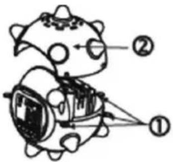
Step one
Gently loosen the buckles with your hand as shown in 1 (5 buckles in all).
Remove the upper cover as shown in 2.


text_image
Hand-drawn cartoon character with labeled parts, likely illustrating a concept or concept in physics or mathematics.-
Buckles
-
Upper cover
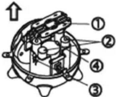
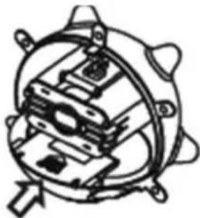
Step two
Press down the battery buckle with your hand (as shown in 3, and remove the battery cover).
Battery buckle Big opening.
Insert 4 pieces of 1.5 V AA batteries as per the correct polarity (positive or negative symbols are shown on the battery cover and the + symbol is the positive polarity of the battery).
text_image
Technical diagram of a mechanical device with numbered components and an upward arrow indicating direction-
Battery cover
-
Battery
-
Battery buckle
-
Buckle
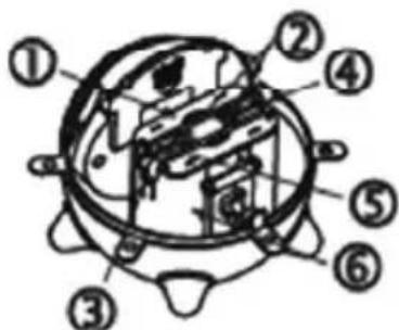
Step three
Replace the battery cover and observe the correct direction of the battery cover (The smaller opening of the battery cover should be against the battery buckle. Place the bigger and smaller openings properly onto the battery cabinet and press down the middle part, ensuring that the two buckles in the middle are in place).
text_image
Technical diagram of a mechanical component with numbered parts labeled ① through ⑥-
Battery cover
-
Battery buckle
-
Battery buckle
-
Big opening
-
Small opening
-
Battery cabinet
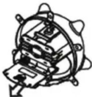
Step four
Push the battery cover outward, remove it and insert 2 pieces of 1.5 ~V AAA batteries as per the correct symbols of polarity (correct symbols of positive and negative polarity are shown inside the battery box and the + symbol is the positive polarity of the battery).
natural_image
Mechanical component diagram showing a gear-like assembly with no visible text or symbolsPush battery cover outward
Step five
Push the battery cover in, as shown in the above diagram. Replace the upper cover and buckle it well.
natural_image
Mechanical assembly diagram showing internal components and mounting brackets (no text or labels)Push the battery cover in
Safety precautions:

text_image
CAUTION RISK OF ELECTRIC SHOCK DO NOT OPENTo reduce risk of electric shock, this product should ONLY be opened by an authorized technician when service is required. Disconnect the product from mains and other equipment if a problem should occur. Do not expose the product to water or moisture.
Maintenance:
Clean only with a dry cloth. Do not use cleaning solvents or abrasives.
Warranty:
No guarantee or liability can be accepted for any changes and modifications of the product or damage caused due to incorrect use of this product.
General:
Designs and specifications are subject to change without notice.
All logos brands and product names are trademarks or registered trademarks of their respective holders and are hereby recognized as such.
Keep this manual and packaging for future reference.
Attention:
This product is marked with this symbol. It means that used electrical and electronic products should not be mixed with general household waste. There is a separate collections system for these products.
DEUTSCH
Hauptfunktionen
text_image
Diagram of a cartoon character with labeled parts, showing eye and ear structures with numbered annotations.text_image
Technical diagram of a mechanical device with numbered components and an upward arrow indicating directiontext_image
Technical diagram of a mechanical device with numbered components for identificationnatural_image
Mechanical component diagram showing internal gears and housing (no text or symbols)natural_image
Technical line drawing of a mechanical component with no visible text or symbolstext_image
Diagram of a cartoon character with labeled parts, showing eye positions and numbered annotations.Attache des piles ©Big opening.
text_image
Technical diagram of a mechanical component with numbered parts and an upward arrow indicating directiontext_image
Technical diagram of a mechanical device with numbered components for identificationnatural_image
Mechanical assembly diagram showing a rotating component with no visible text or symbolsnatural_image
Technical line drawing of a mechanical assembly with no visible text or symbolstext_image
Hand-drawn cartoon character with labeled parts, likely illustrating a concept or concept in physics or mathematics.- Klemmen
- Bovendeel
Stap twee
text_image
Technical diagram of a mechanical device with numbered components and an upward arrow indicating directiontext_image
Technical diagram of a mechanical device with numbered components for identificationnatural_image
Mechanical component diagram showing a gear-like structure with no visible text or symbolsnatural_image
Technical line drawing of a mechanical assembly with no visible text or symbolstext_image
Diagram of a cartoon character with labeled parts, showing eye and ear structures with numbered annotations.text_image
Technical diagram of a mechanical device with numbered components and an upward arrow indicating directiontext_image
Technical diagram of a mechanical device with numbered components for identificationnatural_image
Mechanical assembly diagram showing a rotating component with no visible text or symbolsSpingere il coperchio batterie verso l'esterno
Passo cinque
natural_image
Technical line drawing of a mechanical assembly with no visible text or symbolstext_image
Diagram of a cartoon character with labeled parts, showing eye positions and numbered annotations- Broches
- Cubierta superior
Paso dos
text_image
Technical diagram of a mechanical device with numbered components and an upward arrow indicating directiontext_image
Technical diagram of a mechanical device with numbered components for identificationnatural_image
Mechanical assembly diagram showing a rotating component with internal components (no text or labels)natural_image
Mechanical assembly diagram showing internal components and mounting holes (no text or labels)text_image
Diagram of a cartoon character with labeled parts, showing eye and body parts connected by lines.- Csatok
- Felső fedél
Második lépés
text_image
Technical diagram of a mechanical component with numbered parts and an upward arrow indicating directiontext_image
Technical diagram of a mechanical component with numbered parts labeled ① through ⑥natural_image
Mechanical assembly diagram showing a rotating component with springs and housing (no text or labels)natural_image
Mechanical assembly diagram showing internal components and mounting holes (no text or labels)text_image
Diagram of a cartoon character with labeled parts, showing eye and ear structures with numbered annotations.text_image
Technical diagram of a mechanical component with numbered parts and an upward arrow indicating direction- Paristokotelon kansi
- Paristo
- Pariston kiinnike
- Kiinnike
Vaihe 3
text_image
Technical diagram of a mechanical device with numbered components for identificationnatural_image
Mechanical assembly diagram showing a rotating component with internal components (no text or labels)natural_image
Mechanical assembly diagram showing internal components and mounting holes (no text or labels)text_image
Diagram of a cartoon character with labeled parts, showing eye positions and numbered annotations- Spänne
- Övre skydd
Steg två
Batteri spänne ©Big opening.
text_image
Technical diagram of a mechanical component with numbered parts and an upward arrow indicating direction- Batteri skydd
- Batteri
- Batteri spänne
- Spänne
Steg tre
text_image
Technical diagram of a mechanical component with numbered parts labeled ① through ⑥natural_image
Mechanical component diagram showing a rotating fan and housing (no text or symbols)natural_image
Mechanical assembly diagram showing internal components and mounting holes (no text or labels)Skljut in batteriskyddet.
text_image
Diagram of a cartoon character with labeled parts, showing eye positions and connections-
Svorky
-
Horní kryt
Krok 2
text_image
Technical diagram of a mechanical device with numbered components and an upward arrow indicating direction- Kryt prostoru pro baterie
- Baterie
- Svorka baterie
- Svorka
Krok 3
text_image
Technical diagram of a mechanical device with numbered components for identification- Kryt prostoru pro baterie
- Svorka baterie
- Svorka baterie
- Velký otvor
- Malý otvor
- Prostor pro baterie
Krok 4
natural_image
Mechanical component diagram showing internal components and mounting brackets (no text or symbols)natural_image
Mechanical assembly diagram showing internal components and mounting holes (no text or labels)text_image
Diagram of a cartoon character with labeled parts, showing eye and lens components-
Elemente de prindere
-
Capac superior
Pasul doi
text_image
Technical diagram of a mechanical component with numbered parts and an upward arrow indicating directiontext_image
Technical diagram of a mechanical device with numbered components for identificationnatural_image
Mechanical component diagram showing a gear-like structure with no visible text or symbolsnatural_image
Mechanical assembly diagram showing internal components with no visible text or symbolstext_image
Diagram of a cartoon character with labeled parts, showing eye and lens components and numbered annotations.-
Kríkoí
-
Άνω κάλυμμα
2 βήμα
text_image
Technical diagram of a mechanical component with numbered parts and an upward arrow indicating directiontext_image
Technical diagram of a mechanical device with numbered components for identificationnatural_image
Mechanical component diagram showing internal gears and housing (no text or symbols)natural_image
Cross-sectional diagram of a mechanical device with internal components and mounting brackets (no text or symbols)text_image
Diagram of a cartoon character with labeled parts, showing eye and lens components and directional arrows.- Spænder
- ∅verste låg
Trin to
text_image
Technical diagram of a mechanical device with numbered components and an upward arrow indicating directiontext_image
Technical diagram of a mechanical device with numbered components for identificationnatural_image
Mechanical component diagram showing a rotating fan and housing (no text or symbols)Skub batterilåget udad.
Trin fem
natural_image
Technical line drawing of a mechanical assembly with no visible text or symbolsSkub batterilåget ind.
text_image
Diagram of a cartoon character with labeled parts, showing eye positions and numbered annotations- Spenner
- ∅vre deksel
Trinn to
text_image
Technical diagram of a mechanical device with numbered components and an upward arrow indicating directiontext_image
Technical diagram of a mechanical device with numbered components for identificationnatural_image
Mechanical assembly diagram showing a rotating component with no visible text or symbolsSkyv batteridekselet ut.