iCSPDA2T02 - Flat screen mount Chief - Free user manual and instructions
Find the device manual for free iCSPDA2T02 Chief in PDF.

User questions about iCSPDA2T02 Chief
0 question about this device. Answer the ones you know or ask your own.
Ask a new question about this device
Download the instructions for your Flat screen mount in PDF format for free! Find your manual iCSPDA2T02 - Chief and take your electronic device back in hand. On this page are published all the documents necessary for the use of your device. iCSPDA2T02 by Chief.
USER MANUAL iCSPDA2T02 Chief
Milestone AV Technologies, and its affiliated corporations and subsidiaries (collectively, "Milestone"), intend to make this manual accurate and complete. However, Milestone makes no claim that the information contained herein covers all details, conditions or variations, nor does it provide for every possible contingency in connection with the installation or use of this product. The information contained in this document is subject to change without notice or obligation of any kind. Milestone makes no representation of warranty, expressed or implied, regarding the information contained herein. Milestone assumes no responsibility for accuracy, completeness or sufficiency of the information contained in this document.
Chief® is a registered trademark of Milestone AV Technologies. All rights reserved.

IMPORTANT WARNINGS AND CAUTIONS!
WARNING: A WARNING alerts you to the possibility of serious injury or death if you do not follow the instructions.

CAUTION: A CAUTION alerts you to the possibility of damage or destruction of equipment if you do not follow the corresponding instructions.

WARNING: Failure to read, thoroughly understand, and follow all instructions can result in serious personal injury, damage to equipment, or voiding of factory warranty! It is the installer's responsibility to make sure all components are properly assembled and installed using the instructions provided.

WARNING: Failure to provide adequate structural strength for this component can result in serious personal injury or damage to equipment! It is the installer's responsibility to make sure the structure to which this component is attached can support five times the combined weight of all equipment. Reinforce the structure as required before installing the component.

WARNING: Exceeding the weight capacity can result in serious personal injury or damage to equipment! It is the installer's responsibility to make sure the combined weight of all components attached to the iCSPDA2 does not exceed 40 lbs (18kg).

AVISOS Y PRECAUCIONES IMPORANTES!

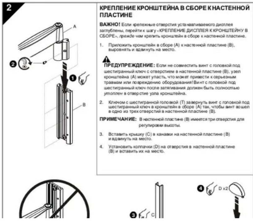
Installation Instructions

IMPORTANT! If installing a display with recessed mounting holes, then proceed to "INSTALL DISPLAY TO ARM ASSEMBLY" before installing arm assembly to wall plate.
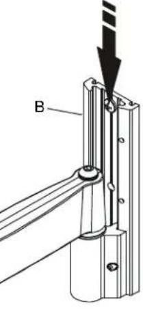
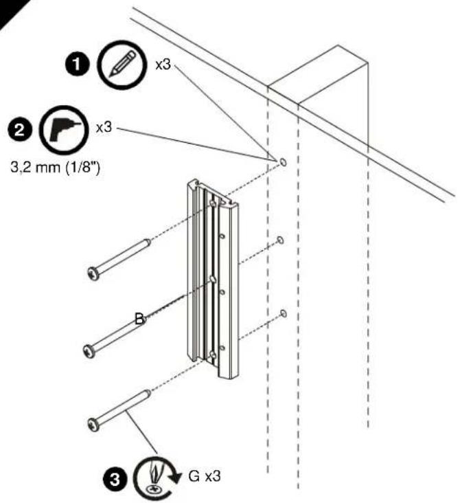
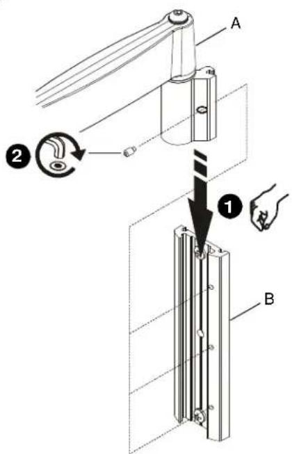
- Align arm assembly (A) with wall plate (B) and slide into position.
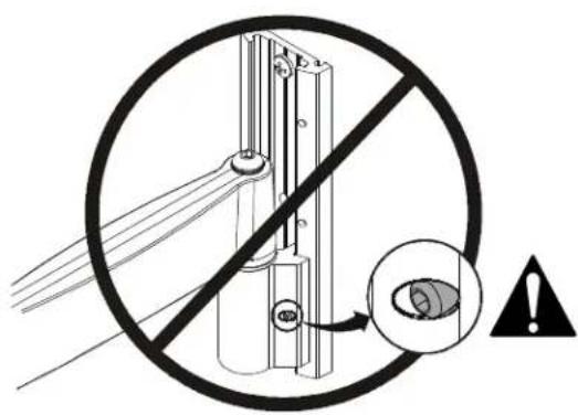
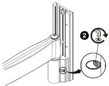
WARNING: Failure to align hex head screw with hole in wall plate (B) may allow arm assembly (A) to fall, resulting in serious personal injury or damage to equipment! Hex head screw should fully recede into arm assembly hole after tightening. - Using hex key (T), tighten hex head screw in arm assembly (A) ensuring that screw engages one of three holes in wall plate (B).
NOTE: Three holes are provided in wall plate (B) to provide height adjustment.
- Align cover (C) with grooves in wall plate (B) and slide into position.
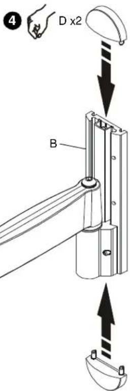
- Align caps (D) with holes in wall plate (B) and slide into position.
3
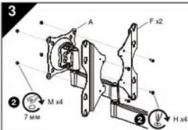
| 3 7mm F x2 M x4 H x4 | INSTALL DISPLAY TO ARM ASSEMBLY 1. If display has a 75 x75mm or 100 x 100mm mounting pattern, proceed to Step 3A ("Flush Mounting Holes") or Step 3B ("Recessed Mounting Holes"), as applicable. Otherwise, continue below. 2. Install screws (H) through brackets (F) and arm assembly (A) into nuts (M). 3. Proceed to Step 3A ("Flush Mounting Holes") or Step 3B ("Recessed Mounting Holes"), as applicable. |
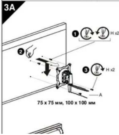
| 3A 75 x 75mm, 100 x 100mm | Flush Mounting Holes IMPORTANT! This procedure only applicable when 4mm or 6mm diameter mounting holes are flush with back surface of display. WARNING: Exceeding the weight capacity can result in serious personal injury or damage to equipment! It is the installer's responsibility to make sure the combined weight of all components attached to the iCSPDA2 does not exceed 40 lbs (18 kg). CAUTION: Using screws of improper size may damage your display! Proper screws will easily and completely thread into display mounting holes. CAUTION: Inadequate thread engagement in display may cause display to fall! Back out screws ONLY as necessary to allow installation to arm assembly. 1. Install two screws (H or Q, as applicable) into the upper mounting holes on display. Thread screws completely into display, then back out 3 complete turns. NOTE: 100 x 100 and 200 x 200 mounting hole patterns shown; 75 x 75mm and 100 x 200mm patterns similar. 2. Align display so that screws installed in previous step fit into upper pair of teardrop mounting holes. Lower display firmly into place. NOTE: Display will be hanging on upper two screws. 3. Install two remaining screws (H or Q, as applicable) through lower pair of teardrop mounting holes. • If installing screws (H) through brackets (F), then install washers (L) under screw heads (H). 4. Tighten all four screws (H or Q, as applicable). Do not overtighten! |
3B
Recessed Mounting Holes
IMPORTANT! This procedure only applicable when 4mm diameter mounting holes are recessed into back surface of display.

WARNING: Exceeding the weight capacity can result in serious personal injury or damage to equipment! It is the installer's responsibility to make sure the combined weight of all components attached to the iCSPDA2 does not exceed 40 lbs (18 kg).
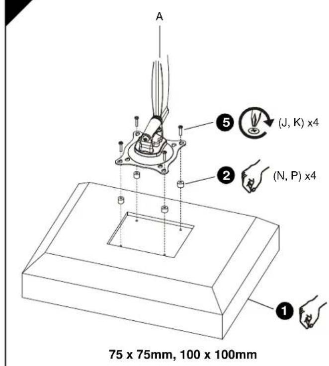
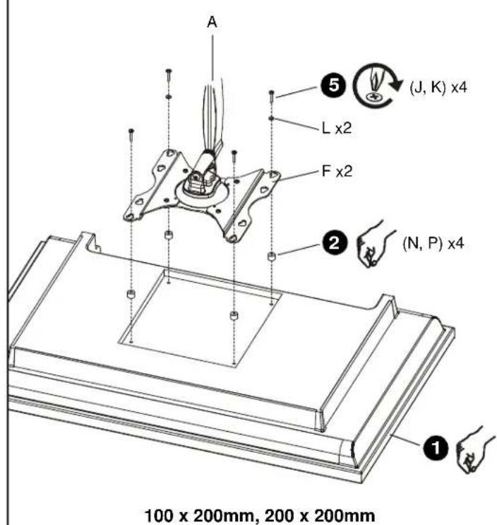
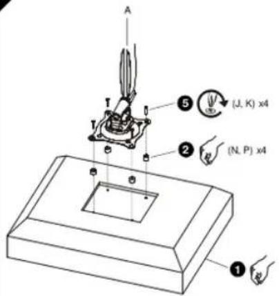
- Carefully place display face down on protective surface.
- Place four spacers (N or P, as applicable) over each mounting hole on back of display. Select shortest spacer which will provide adequate fill. All spacers must be same length.
NOTE: 100 × 100 and 200 × 200 mounting hole patterns shown; 75 × 75mm and 100 × 200mm patterns similar.
- Select screw length:
If using spacers (N), then use screws (J).
- If using spacers (P), then use screws (K).
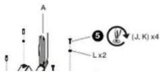
NOTE: If installing screws (J, K) through brackets (F), then also use washers (L) for lower pair of teardrop mounting holes.
- Orient arm assembly (A) so that teardrop mounting holes are aligned with holes in spacers (N or P, as applicable).

CAUTION: Using screws of improper size may damage your display! Proper screws will easily and completely thread into display mounting holes.
- Install screws (J or K, as applicable) through washers (L, if applicable), teardrop mounting holes, and spacers (N or P, as applicable), into display. Tighten all four screws. Do not overtighten!
- Continue with "INSTALL ARM ASSEMBLY TO WALL PLATE."
1
INSTALACION DE LA PLACA DE MONTAJE EN PARED
ARMCONSTRUCTIE AAN WANDPLAAT BEVESTIGEN
EDyPENKDEHNE:Ecm He oecneHn
DOCTAOHYO KOHCTPYKIAOHHOYIPOHOHOTB DNR
DHHIOKO COMBOHHTA,30MOXET NOHN
C6pe3HeT B4aMn NIN NOPQxDHNE
060yobDnA. HIO.OOCYCTNANHOOeTcYbONAOK 063aHNOpCnEHNbTAEM.TTOBbKOHTCPYKJH
KKTOPOR KPERTOR DAHM KOMTHOENT, MONT
Baeepkatah Harpy3xy, paabnyo nntnpiKATHMO Bcye Boero oobopybaHAn. Eehne Heo6bmo, nepey cytAchoNKO KOMIOHEHTA yCyrHNTb ABO KOHCTPQUck
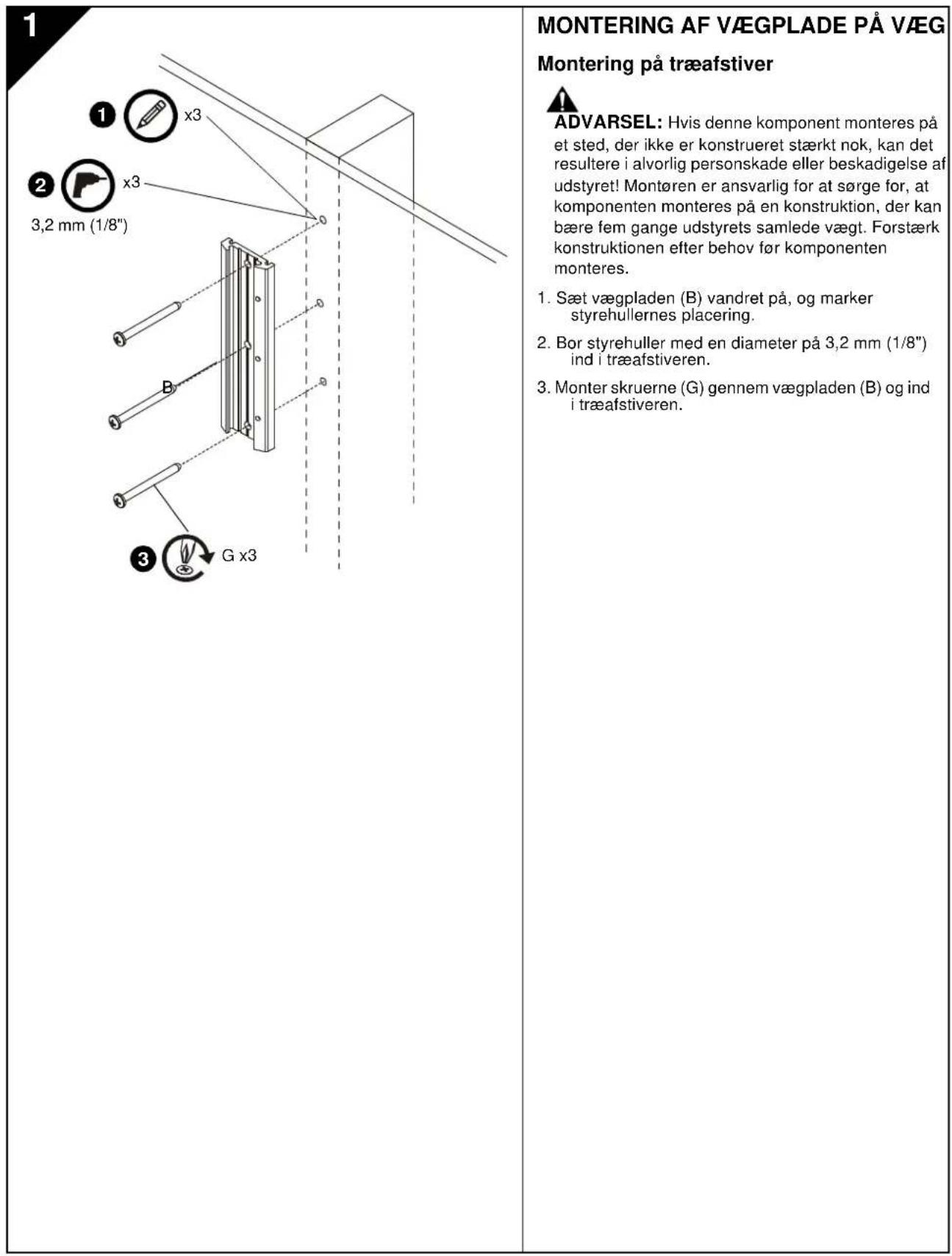
- 北罗布尼娃纳克夫斯基(B)和罗夫斯基
- nongenchenhaohanpaowu(O)和O
- IpocsepiHxI npaHApKuOy OteEpyTb DAMETOM 3,2 MM (1/8) B depEnHOM KAPok
- 3aeeepyIyyuynm (G) epeeHnactehyn H nnaey (B) epeepnnkkapac.
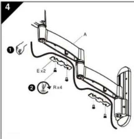
KPENIEHNE DNCNIEK KPOHHTEHY B C6OPE
- EcmpanmmeBn 75mmNpnexnHnepxntbT 75mm 75mm 100X100 mm 100 X100 mm nnnn nnnn nnnn nnnn nnnn nnnn nnnn nnnn nnnn nnnn nnnn nnnn nnnn nnnn nnnn nnnn nnnn nnnn nnnn nnnn nnnn nnnn nnnn nnnn nnnn nnnn nnnn nnnn nnnn nnnn nnnn nnnn nnnn nnnn nnne
2.3aBepHTy BnHbTI (H)pee3 cKo6b (F) HpOOnTu8H a cbOp (A) a Raim (M). - Napeiin K uay 3A (<Kpenexhne OtepctnK. paoononek 3aandnou<) nK uay 3B (<Any6nne Kpenekohne OtepctnK.a 3aNNMocnO onoay
Kpenekhbe OteBepctn,paononoXehnhbe 3anoNnpo
BAKHOI 3ra npoueDpypnpmeHmHaToIaKoEChn XpehnoHeO tBepCTNaDAMTPO4 MM m6 MM paonNoKeHb 3azo 0uC zAaHOBePXPHOxO aDQNner.

PNDYPTPEKDEHNE: Pnepbawbdoynctmnn Becobn Karpny MoKt NnBnEb OpeBHe Tpaamn Wnnpaekpne Hne 06bpOanHnI RIO, oocyeTANrOeue yctahOBx, OB3AHO npocpeDtt 3A TET, YTOB cymmapna Maccacbcx KomoHOBNc, YCTaONBeHnBnHa HA ICSPDA2, He ppebnua18Kr (40yfHTOB).

PNEOCTEPEXEHME: INI NIOHOBBAHBIHTOB HNOEDQHOHOA PMA BO3MOHO NOPEXDHGEHN DINNIE BINTHn pRABHnHO HO PA3Me nHnNOHOCTBO BHHNNHACOT K BKNKENHO OTBETCTHJ DNCLNER.
3B
75×75MM,100×100MM
3ayn6nHHbIe KpenexKbIe OTBepCTH
BAKHO! 3ra npoea ypa nmaeHMA ToIbKO e cIM KxepKHeO tBepCTN daAMETpOM 4 MM 3a2y6nHb H aDIO NOEPEHOCTb PcHIN

N PDEYINPEKHEME: PpeBHeMeDONYCIMOMI BEOAEB HAPyERMOKET NOEHNBcEPENH TPAEMN WnnepeBdHnO 06pOyDaaHn1 Iaepo, Ocyue CTANbUe yCTAOHB, OB3AnHO pncOpEnb4T 3A TEM, YTObS CYMMAE MAcc AECK KOMONHHTo, YctAHOBNEHbK HA cSPDAZ, He npeBuaa 18 k (40 dyfno).
- Axxypatho NONOKHTI, darnne nniueBt ctoPOHBA H3A 3aauTTHYO NOEbEXHOCTb
- POMECTBHTY BPTTCTAETKMOHNNBE TBYTN (NVIHN P, ABAHCMOTCOT CNTUATyAN) HA YTEK KPEKEXHXI XOBETCR HA ZADHE CTENK DNJIINER. BIBOPAT CAMBLE KOPOTKTN BYTKO, DOCTAOCHNO DE NINHE BOE ATYNIOJONIKH6bTTbOH OHNJINHH.
PIMMEYAHNE: Nocaaa 1 a5nnonepeneo
OTBepcn 100x100 MM
200x200MM,uaaNohei
75 × 75 mm × 100 × 200 mm
0
- Buxpaatb bntb HymnoH OunhB:
EcnwnonbsyntaBtynnN
ONON308aTbBHTbJ
Ecnna nannnayotat ytnnn (P) nannnabotsa bntn (K).
PIMMEAHHE: EcmBnhtb (J.K) nponyckxotcr
Hep306b(F), Taekoe konno3a8a
Aai6i(L) dna Hauke npny
KanneMkKpKpEeKbXb OTaeptT.
- PACONONOMATH KPOHUIJETB H 605E (A) Tak, UTOHAI KANGAN MONGKONGYUO ANOCTO

2
MONTERING AF ARMENHED PÅ VæGPLADE
MANUFACTURERS DECLARATION OF CONFORMITY
For
Product identification:
Model/type
iCSPDA2
Category (description)
Mounting devices, Stands and other Accessories, to be used with entertainment electronics
Brand
iC
Manufacturer:
CSAV Inc.
8401 Eagle Creek Parkway
Savage, MN 55378
EU Representative:
CSAV Inc.
Fellennoord 130 5611
ZB Einhoven
The Netherlands
31(0)402668620
| Concerning | ||||
| EMC | Safety | |||
| A sample of the product has been tested by: | Not Applicable | CSAV Inc. | ||
| Test report reference | . | |||
| Applied standards | EN 60065 :2002 | |||
Means of conformity
We declare under our sole responsibility that this product is in conformity with Directive 93/68/EEC (Marking), 98/37/EC (Machinery) 2001/95/EC (Safety) and/or complies to the essential requirements and all other relevant provisions of the based on test results using (non)harmonized standards in accordance with the Directives mentioned

Manufactured by CHIEF®
iC Mounting Solutions
USA·8401 Eagle Creek Parkway, Suite 700·Savage, Minnesota 55378·800.572.1373
Europe/Middle East/Africa ^+ 31 (0)40 2668620
www.icmounts.com