6 Acoustimass Speaker System - Speakers BOSE - Free user manual and instructions
Find the device manual for free 6 Acoustimass Speaker System BOSE in PDF.
User questions about 6 Acoustimass Speaker System BOSE
0 question about this device. Answer the ones you know or ask your own.
Ask a new question about this device
Download the instructions for your Speakers in PDF format for free! Find your manual 6 Acoustimass Speaker System - BOSE and take your electronic device back in hand. On this page are published all the documents necessary for the use of your device. 6 Acoustimass Speaker System by BOSE.
USER MANUAL 6 Acoustimass Speaker System BOSE
Acoustimass® 6 Series III Acoustimass® 10 Series IV
Please read this owner's guide
Please take the time to follow this owner's guide carefully. It will help you set up and operate your system properly and enjoy all of its advanced features. Please save your owner's guide for future reference.
For your safety
WARNING: To reduce the risk of fire or electric shock, do not expose the powered Acoustimass® module to rain or moisture.
WARNING: No naked flame sources, such as lighted candles, should be placed on the apparatus.
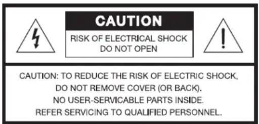
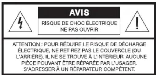
These CAUTION marks are located on the rear of the Acoustimass module:
The lightning flash with arrowhead symbol within an equilateral triangle is intended to alert the user to the presence of uninsulated, dangerous voltage within the system enclosure that may be of sufficient magnitude to constitute a risk of electric shock.

The exclamation point within an equilateral triangle, as marked on the system, is intended to alert the user to the presence of important operating and maintenance instructions in this owner's guide.
CAUTION: To prevent electric shock, match the wide blade of the line cord plug to the wide slot of the AC (mains) receptacle. Insert fully.
This product conforms to the EMC Directive 89/336/EEC and to the Low Voltage Directive 73/23/EEC. The complete Declaration of Conformity can be found on www.bose.com/static/compliance/index.html.
Additional safety information
See the additional safety information on the Important Safety Instructions page enclosed with your speaker system.
For your records
The system serial number is located on the rear of the Acoustimass module.
Serial number:
Dealer name:
Dealer phone: Purchase date:
Please keep your sales receipt and warranty card together with this owner's guide.
SETTING UP 4
Before you begin 4
Unpacking the carton 4
Placing your speakers to achieve realistic home theater sound 5
Front left and right speakers 6
Center speaker 6
Rear speakers 6
7
Making the connections 7
Connecting speakers to the Acoustimass module 7
Connecting the Acoustimass module to the receiver 9
Checking the connections 10
Getting the most from your home theater speakers 11
Adjusting the bass/room compensation 11
Adjusting the LFE level 11
Setting your digital surround sound receiver 12
Receiving a digital audio signal 12
Setting your analog surround sound receiver 12
REFERENCE 13
Troubleshooting 13
Customer service 14
Cleaning the speakers 14
Limited warranty 14
Accessories 14
Technical information 15
Before you begin
We appreciate your choice of the Bose® Acoustimass® 6 Series III or Acoustimass 10 Series IV home entertainment speaker system.
The Acoustimass 6 features five small cube speakers, while the Acoustimass 10 system features four cube speaker arrays and a center front speaker. These speakers, together with the Acoustimass module, reproduce the full spectrum of multi-channel digital programming for a powerful and realistic home theater experience.
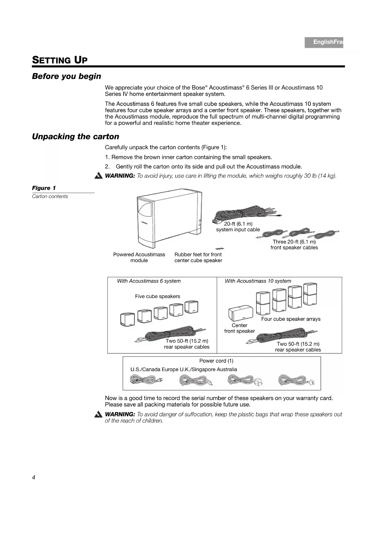
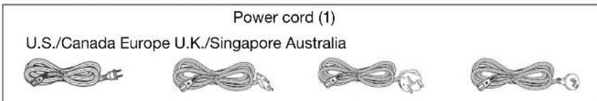
Unpacking the carton
Carefully unpack the carton contents (Figure 1):
- Remove the brown inner carton containing the small speakers.
- Gently roll the carton onto its side and pull out the Acoustimass module.
WARNING: To avoid injury, use care in lifting the module, which weighs roughly 30 lb (14 kg).
Carton contents
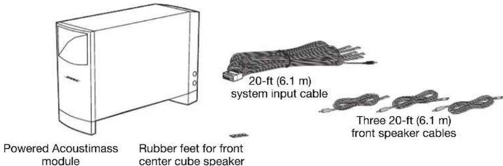
Figure 1
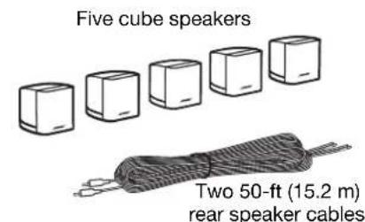
With Acoustimass 6 system
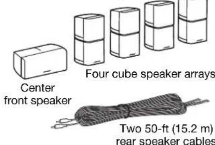
With Acoustimass 10 system
Now is a good time to record the serial number of these speakers on your warranty card. Please save all packing materials for possible future use.
WARNING: To avoid danger of suffocation, keep the plastic bags that wrap these speakers out of the reach of children.
Placing your speakers to achieve realistic home theater sound
Keep these guidelines in mind when choosing a location for each speaker:
- The Acoustimass® module should be at least 2 feet (.6 m) from your TV set to prevent interference.
- All of the small speakers are magnetically shielded to prevent interference with a TV picture.
- Select a stable and level surface for each of the small speakers. Vibration can cause them to move, particularly on smooth surfaces like marble, glass, or highly polished wood. To prevent this problem, rubber feet are provided for attachment to the bottom of the center front speaker.
Note: You may order additional rubber feet, free of charge, by contacting Bose. Refer to the address list included in the carton.
- In an Acoustimass 10 system, the center front speaker is for use at the front of the room and near the center of your TV. The other cube array speakers are identical and can be placed interchangeably around the room (Figure 2a and 2b).
- The top and bottom cube on each cube array speaker can be rotated to create room-filling sound patterns.
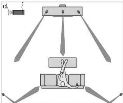
- In the Acoustimass 6 system, all five single cube speakers are identical and can be placed interchangeably around the room (Figure 2c and 2d).
The shape and size of your room and location of the furniture in it will affect your choice of speaker locations. Use the examples below as the basis, but not the rule, for your home theater setup.
Figure 2
Sample speaker placement (a and c) and performance results (b and d)

Acoustimass 10 Series IV system
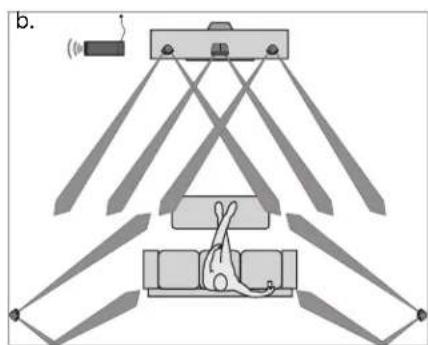
Acoustimass 6 Series III system
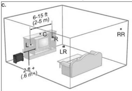
Front left and right speakers
The goal for these is to create a sound image wider than the screen that seems natural to viewers sitting anywhere in the room.
- Place these two front speakers on either side of your TV.
- Keep them from 6 feet (2 m) to 15 feet (5 m) apart (as shown in Figure 2 on page 5).
Center speaker
Sound from the center speaker should seem to come from within the picture to give the most realistic performance of on-screen action and dialogue.
- Place the center speaker above, on top of, or below your TV. Do NOT rest the weight of the TV on the speaker.
- Keep the speaker in line with the vertical center of the screen, if possible, for the most accurate reproduction of dialogue (as shown in Figure 2 on page 5).
CAUTION: Before placing the center speaker on top of your television, attach the four supplied rubber feet to the bottom of the speaker. Position two of the feet near the front edge and close together on the bottom surface. Place the other two feet at the rear outer edges on the bottom.
Rear speakers
While the rear (surround) speakers may deliver some dialogue, they serve primarily to deliver discrete sounds and special effects that expand the visual image. They help bring the viewer into the center of the action.
Choose locations that are practical and convenient, while considering these recommended guidelines:
- Position the left and right rear speakers so they can deliver sound on both sides of the viewer, rather than from directly behind (as shown in Figure 2 on page 5).
- Place these speakers at the same height as the ears of a seated viewer or higher.
- For the Acoustimass® 10 system, rotate the top and bottom sections of the rear cube speaker arrays to direct the sound to the front and back of the listener (see Figure 3 on page 7).
- For the Acoustimass 6 system, aim the rear cube speakers slightly behind the listener or reflect the sound off the rear wall (see Figure 2 on page 5).
Powered Acoustimass module
Acoustimass® speaker technology makes it difficult to locate the source of low-frequency sound from this module. So feel free to hide it from view, and:
- Locate the module at the same end of the room as the TV screen.
- Keep the module at least 2 feet (.6 m) from your TV set to prevent interference.
- To increase bass effects, turn the front opening toward a wall; turn it away from the wall to decrease bass effects.
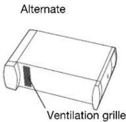
- Keep both the front opening and the ventilation grille on the bottom of the module at least 2 inches (5 cm) from any other surface.
- Do not block the ventilation grilles located on the bottom of the module. Impeding ventilation can cause a reduction in the bass-frequency output from the module.
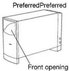
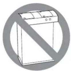
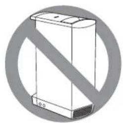
Figure 3
Position options for your Acoustimass module
Making the connections
Only the Acoustimass module connects to your receiver. The small speakers all connect directly to the Acoustimass module.
WARNING: Connecting the small speakers to a receiver can result in damage to your system and possible electric shock.
Connecting speakers to the Acoustimass module
Insert the connector on each speaker cable into the jack on the module. Refer to the label on each connector to match it to the proper jack.
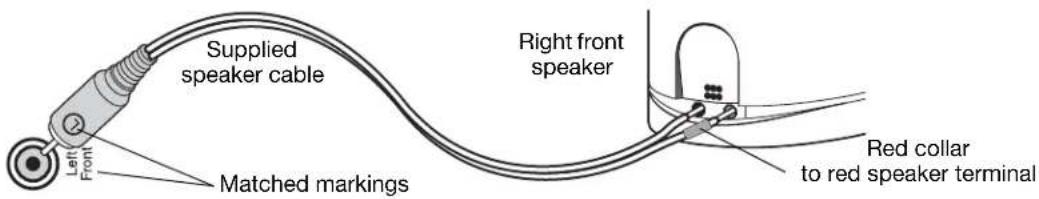
Figure 4
Speaker cable connection to an output jack on the module and to the speaker
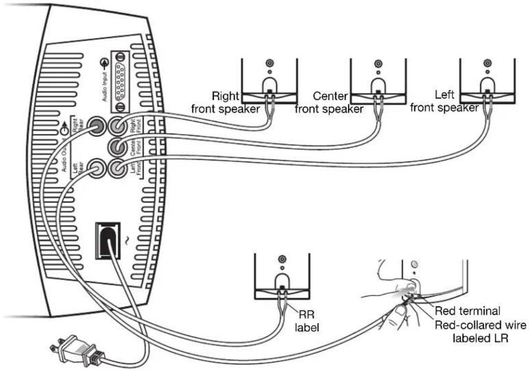
- Use the supplied 20-ft (6.1 m) speaker cables for the three front speakers.
Insert the connectors, as labeled, into jacks on the module as follows (Figure 5 on page 8).
- R goes into the jack labeled Right Front.
C goes into the jack labeled Center Front. -
L goes into the jack labeled Left Front.
-
Use the supplied 50-ft (15.2 m) speaker cables for the speakers at the rear of your room (Figure 5).
Insert them into the jacks on the module as follows:
- RR goes into the jack labeled Right Rear.
-
LR goes into the jack labeled Left Rear.
-
At the other end of each cable, insert the red-collared (+) wire into the red (+) terminal on one speaker. Insert the other wire into the other terminal (Figure 5).
Notice a label on each red-collared wire that matches it to the proper speaker:
| ·L for the speaker at the left front ·LR for the speaker at the left rear |
| ·R for the speaker at the right front ·RR for the speaker at the right rear |
| ·C for the speaker at the center front |
Figure 5
Completing connections of the small speakers to your Acoustimass module
Acoustimass 10 system module
Connecting the Acoustimass® module to the receiver
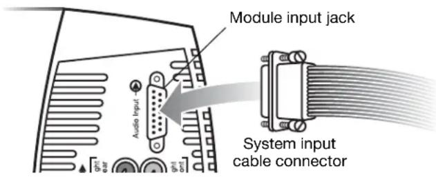
The system input cable is 20 feet (6.1 m) long and connects to your surround receiver. Unlike the speaker cables, this input cable has a multi-pin connector that inserts into the Audio Input jack on the module (Figure 6).
System input cable connection
Figure 6
Unzipping the paired wires
At the other end of the system input cable, multiple wire pairs "unzip" for easy reach and insertion into terminals on your receiver. A red collar marks a wire as positive (+) wire.
CAUTION: Do NOT connect your module to the TV, which lacks the required amplification.
The single RCA connector at that end is for use ONLY with a receiver that handles low-frequency effects and provides an LFE/SUBWOOFER jack (Figure 7).
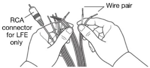
Figure 7
CAUTION: Before making these connections, turn off your receiver to prevent unwanted noises when you plug the Acoustimass® module into it.
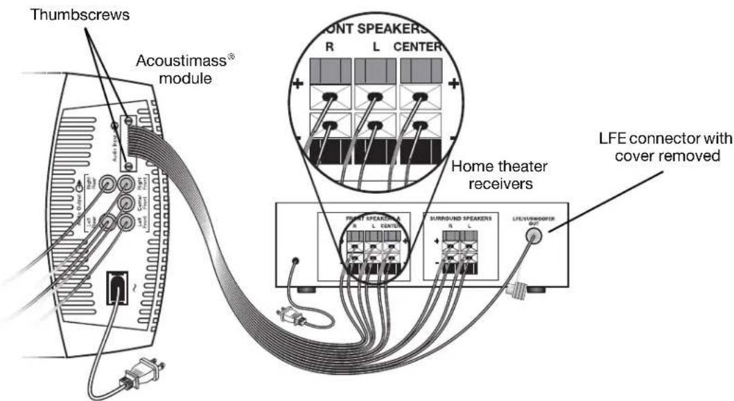
To make the connections (Figure 8 on page 10):
- Insert the multi-pin connector on the system input cable into the input jack on the Acoustimass module. Tighten the two thumbscrews to secure the connection.
-
Connect each wire pair on the other end of the system input cable to your surround receiver, which should have audio output terminals labeled:
-
Right, Left, and Center for the front audio channels.
- Right Surround and Left Surround for the rear channels. The specific labels on your receiver may differ slightly.
CAUTION: Do not allow exposed wires to brush against each other; this could damage your receiver.
-
Carefully match the polarity of the connections (+ to + and - to -).
-
Attach each red-collared wire (+) to the appropriate + terminal.
-
Attach each plain wire (-) to the appropriate - terminal.
-
If applicable to your receiver, insert the RCA plug marked LFE on the system input cable into the LFE/SUBWOOFER OUT jack on your surround receiver. Remove the cover first.
Figure 8
Acoustimass® module to receiver connections
Checking the connections
Before plugging in the Acoustimass module, check all connections from the receiver to the the module and the module to the small speakers (Figure 8).
- Make sure all cube speaker arrays are connected to the proper terminals according to their position in your room.
- Check to be sure all wires are connected to your surround receiver with the proper polarity (+ to + and - to - wires). Incorrect wiring can result in a total loss of module output.
- Correct any wiring problems before you plug in your receiver and turn it on.
When all the connections check out, plug the power cord from the Acoustimass module into an AC (mains) outlet. Plug in the receiver also.
Note: Bose recommends using a quality surge suppressor on all electronics equipment. Voltage variations and spikes can damage electronic components in any system. Using a high-quality suppressor (available at electronics stores) can eliminate the vast majority of failures caused by a power surge.
Getting the most from your home theater speakers
With system connections completed and the module plugged in, your Acoustimass® system is now ready for use.
You may want to familiarize yourself with the controls and built-in protections that adjust the audio of this system (Figure 9). They offer options to suit your particular style of use and preferences.
CAUTION: This system provides an automatic protection circuit to help guard against damage from electrical stresses and overload of the system. At high volume levels, the circuit activates to reduce output, which slightly decreases the volume. If you notice this decrease, be aware that your system is functioning as designed. This volume reduction also indicates that power input to the system may exceed safe levels. Sustained listening at these levels is not recommended.
Figure 9
Audio adjustment knobs
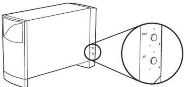
Adjusting the bass/room compensation
After placing the Acoustimass module where you want it, you can fine-tune it for that location. Make this adjustment only as necessary.
For example:
- If the system performance is "thin" or lacks bass, turn the BASS control (shown above) clockwise to increase the low-frequency output of the module.
- If the audio is "boomy" or overemphasizes bass, turn the knob counter-clockwise to reduce the low-frequency output of the module.
The setting made at the factory is meant for use in the most common room arrangements.
Adjusting the LFE level
The LFE level control (shown above) is for use only with receivers that provide an LFE/SUB-WOOFER channel.
By turning the knob, you can adjust the relative level of the low-frequency effects from movie soundtracks. Use it to match the volume level of the LFE channel with volume levels of your other speaker channels.
You can check all levels by using the "test tones" feature on your digital surround sound receiver. For details on using this feature, refer to the owner's guide provided with your surround receiver.
Setting your digital surround sound receiver
Speakers in your Acoustimass® 6 Series III or Acoustimass 10 Series IV system are fully compatible with the audio output of digital surround receivers. The system's integrated signal processing supports full low-frequency reproduction from all channels.
To gain complete advantage of these system capabilities, you may want to adjust some settings on your receiver. To make changes, use the digital display menu on the receiver and refer to the list of recommended settings, below.
Speaker Receiver setting
- Left and right LARGE
Center LARGE - Left and right surround LARGE
LFE/Subwoofer ON
Note: If your receiver provides it, the LFE or Subwoofer option setting should be ON and the crossover value at the lowest number possible, which is typically 80 Hz.
Receiving a digital audio signal
For the digital audio signal from your DVD player to reach your surround receiver, you need a digital audio connection between the DVD player and receiver (Figure 10).
- Use either the Optical or Coaxial input (not both) on the receiver to connect to the digital output from the DVD.
- Be sure to select the digital output in the setup menu of your DVD player.
For additional setup and operating information, please refer to the owner's guide that came with your surround receiver.
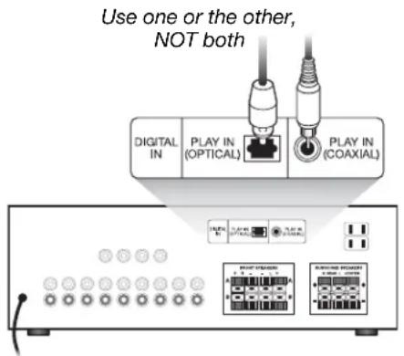
Figure 10
Digital signal receiver connections
Setting your analog surround sound receiver
For analog (non-digital) surround sound applications, we recommend that you set the surround sound center mode of your receiver to Wide. For instructions on how to change this setting, refer to the owner's guide provided with your surround receiver.
Troubleshooting
If you have a problem with your Acoustimass® speaker system, turn off your sound source and try the following solutions. If you still have a problem, contact your Bose® dealer to arrange for service. To contact Bose directly, refer to the address list included in the carton.
| Problem What to do | |
| System does not function at all | ·Make sure the receiver and powered Acoustimass module are plugged into an operating AC outlet and that the receiver is turned on. ·Be sure to select an audio source on the receiver (video, CD, DVD, tuner). |
| No sound • Increase the volume. | ·Disconnect any headphones. ·Check the speaker connections. ·Make sure that both the powered Acoustimass module and the receiver are plugged in. ·For digital sound, be sure a coaxial or optical cable connects the digital output of the DVD player with the digital input on your receiver. ·Be sure the audio source selected is correct. For example, select DVD audio on your receiver to hear the DVD sound. |
| No surround sound • Make | sure the source material contains surround sound. ·If you are using the Dolby Pro-Logic mode on your receiver, make sure surround sound is turned on. ·Be sure the source material (DVD, laser disc, or broadcast programming) is Dolby Digital encoded. ·Be sure your receiver is processing a signal from a Hi-Fi VCR, stereo TV, laserdisc, or DVD player, or other surround sound source. ·If you are using digital programming, verify that the settings are correct at the receiver. |
| No bass | ·Be sure the speaker connections from the receiver to the amplifier are in the correct phase, red-collared wire to red jack (+ to + and - to -). |
| Not enough or too much bass | ·Move your Acoustimass module closer to a wall or corner to increase bass. Move it farther from a wall or corner to decrease bass. ·Adjust the LFE level or Room Compensation control. |
| Sound is distorted • Make | sure speaker wire is not damaged. ·Reduce the volume of external components connected to the receiver. |
Customer service
For additional help in solving problems, contact the Bose Customer Service office appropriate to your area. See the address list included in the carton.
Cleaning the speakers
The cabinets of your Acoustimass speaker system may be cleaned only with a soft dry cloth. Do not use any sprays near the system or allow liquids to spill into any openings. Also, do not use any solvents, chemicals, or cleaning solutions containing alcohol, ammonia, or abrasives.
The grille assemblies on the small speakers may be carefully vacuumed, if necessary. Please note that the drivers are located directly behind the grille cloth and are easily damaged if reasonable care is not taken.
Limited warranty
Your Acoustimass® speaker system is covered by a limited transferable warranty. Details of the warranty are provided on the warranty card that came with your system.
Please fill out the information section on the card and mail it to Bose. Failure to do so, however, does not affect your rights.
Accessories
Bose offers the following accessories in colors to match and add to your enjoyment of the Acoustimass speaker system.
- UTS-20 table stands
- UFS-20 floor stands
UB-20 wall brackets - Speaker wire adapter kit for use with in-wall wiring from the Acoustimass module to the small speakers. Available in black, white, or silver.
For the accessories described above:
Contact your authorized Bose dealer or visit the Bose website: www.bose.com.
For the accessories described below:
Contact your authorized Bose dealer. Or to contact Bose directly, refer to the address list included in the carton.
- Input cable adapter for use with in-wall wiring from the Acoustimass module to the receiver.
- 20-ft (6.1 m) extension cable for use between the Acoustimass module and the receiver.
Technical information
Speaker driver complement
Acoustimass 10 system:
- Cube speaker arrays and center front speaker: Two 2.5'' (6.35 cm) Twiddler™ speakers
- Powered Acoustimass module: Two 5.25" (13 cm) woofers
Acoustimass 6 system:
- Cube speakers: One 2.5'' (6.35 cm) TwiddleFMM speaker
- Powered Acoustimass module: One 5.25" (13 cm) woofers
System power rating
Acoustimass 10 system: Canada:100-127V 50/60 Hz 270W Europe/Australia:220-240V 50/60 Hz 270W
Acoustimass 6 system: U.S./Canada:100-127V 50/60 Hz 135W Europe/Australia:220-240V 50/60 Hz 135W
Connectivity
Acoustimass 10 system:
Compatible with A/V receivers and amplifiers rated from 10 to 200 watts per channel, rated from 4 to 8 ohms
Acoustimass 6 system:
Compatible with A/V receivers and amplifiers rated from 10 to 150 watts per channel, rated from 4 to 8 ohms
Speaker weight/size
Acoustimass 10 system: Cube speaker array and center front speaker: 2.4 lb (1.1 kg) each 6.2^ × 3.1^ × 4.0^ 15.7 cm x 7.9 cm x 10.2 cm
Module: 35 lb (15.8 kg)
16.3"H x 8.1"W x 25.3"D (41.4 cm x 20.6 cm x 64.3 cm)
Acoustimass 6 system:
Cube speaker: 1.1 lb (0.5 kg)
3.1"H x 3.1"W x 4.0"D (7.9 cm x 7.9 cm x 10.2 cm)
Module: 27 lb (12.2 kg)
16.3"H x 8.1"W x 22.3"D (41.4 cm x 20.6 cm x 56.6 cm)