
Z87 Extreme4 - Motherboard ASROCK - Free user manual and instructions
Find the device manual for free Z87 Extreme4 ASROCK in PDF.
| Product type | Motherboard |
| Brand | ASRock |
| Model | Z87 Extreme4 |
| Socket | LGA1150 |
| Chipset | Intel Z87 |
| Compatible processors | 4th Gen Intel Core i7 / i5 / i3 / Xeon / Pentium / Celeron (Haswell) |
| Number of memory slots | 4 x DDR3 DIMM |
| Maximum memory supported | Up to 32GB (estimated) |
| Supported memory frequencies | DDR3-2933+ (OC) / 2800 (OC) / 2400 (OC) / 2133 / 1600 / 1333 / 1066 |
| Audio | Realtek ALC1150, 7.1 channels, SNR 115 dB, TI NE5532 headphone amplifier |
| Network | Gigabit Ethernet (10/100/1000 Mb/s) |
| Storage connectors | 8 x SATA3 (6Gb/s) with RAID 0, 1, 5, 10 support |
| USB | 4 rear USB 3.0 ports + 2 headers (4 ports); 2 rear USB 2.0 ports + 3 headers (6 ports) |
| Video outputs | 1x DVI-I, 1x HDMI, 1x DisplayPort (supports 4K@24Hz) |
| BIOS | Dual UEFI BIOS (primary and backup) |
| Dimensions | ATX (305mm x 244mm) |
| Power supply | 24-pin ATX connector + 8-pin ATX12V connector |
| Maintenance | Clean with a soft dry cloth; do not use liquid products |
| Safety | Overclocking under user's responsibility; overvoltage protection (integrated) |
Frequently Asked Questions - Z87 Extreme4 ASROCK
User questions about Z87 Extreme4 ASROCK
0 question about this device. Answer the ones you know or ask your own.
Ask a new question about this device
Download the instructions for your Motherboard in PDF format for free! Find your manual Z87 Extreme4 - ASROCK and take your electronic device back in hand. On this page are published all the documents necessary for the use of your device. Z87 Extreme4 by ASROCK.
USER MANUAL Z87 Extreme4 ASROCK
Published April 2013
Copyright©2013 ASRock INC. All rights reserved.
Copyright Notice:
No part of this documentation may be reproduced, transcribed, transmitted, or translated in any language, in any form or by any means, except duplication of documentation by the purchaser for backup purpose, without written consent of ASRock Inc.
Products and corporate names appearing in this documentation may or may not be registered trademarks or copyrights of their respective companies, and are used only for identification or explanation and to the owners' benefit, without intent to infringe.
Disclaimer:
Specifications and information contained in this documentation are furnished for informational use only and subject to change without notice, and should not be constructed as a commitment by ASRock. ASRock assumes no responsibility for any errors or omissions that may appear in this documentation.
With respect to the contents of this documentation, ASRock does not provide warranty of any kind, either expressed or implied, including but not limited to the implied warranties or conditions of merchantability or fitness for a particular purpose.
In no event shall ASRock, its directors, officers, employees, or agents be liable for any indirect, special, incidental, or consequential damages (including damages for loss of profits, loss of business, loss of data, interruption of business and the like), even if ASRock has been advised of the possibility of such damages arising from any defect or error in the documentation or product.
The terms HDMI^TM and HDMI High-Definition Multimedia Interface, and the HDMI logo are trademarks or registered trademarks of HDMI Licensing LLC in the United States and other countries.

This device complies with Part 15 of the FCC Rules. Operation is subject to the following two conditions:
(1) this device may not cause harmful interference, and
(2) this device must accept any interference received, including interference that may cause undesired operation.
CALIFORNIA, USA ONLY
The Lithium battery adopted on this motherboard contains Perchlorate, a toxic substance controlled in Perchlorate Best Management Practices (BMP) regulations passed by the California Legislature. When you discard the Lithium battery in California, USA, please follow the related regulations in advance.
"Perchlorate Material-special handling may apply, see www.dtsc.ca.gov/hazardouswaste/perchlorate"

The terms HDMI and HDMI High-Definition Multimedia Interface, and the HDMI logo are trademarks or registered trademarks of HDMI Licensing LLC in the United States and other countries.

Manufactured under license under U.S. Patent Nos: 5,956,674; 5,974,380; 6,487,535; 7,003,467 & other U.S. and worldwide patents issued & pending. DTS, the Symbol, & DTS and the Symbol together is a registered trademark & DTS Connect, DTS Interactive, DTS Neo:PC are trademarks of DTS, Inc. Product includes software.
DTS, Inc., All Rights Reserved.


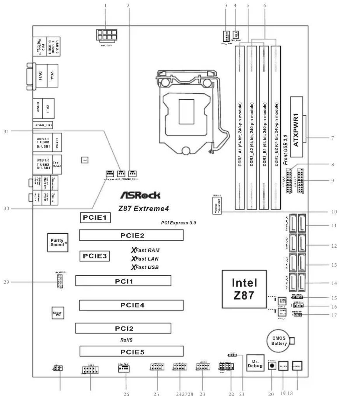
Motherboard Layout
No. Description
1ATX 12V Power Connector (ATX12V1)
2 Chassis Fan Connector (CHA_FAN2)
3 CPU Fan Connector (CPU_FAN1)
4 CPU Fan Connector (CPU_FAN2)
5 2 x 240-pin DDR3 DIMM Slots (DDR3_A1, DDR3_B1)
6 2 x 240-pin DDR3 DIMM Slots (DDR3_A2, DDR3_B2)
7 ATX Power Connector (ATXPWR1)
8 USB 3.0 Header (USB3_4_5) (ASMedia Hub)
9 USB 3.0 Header (USB3_6_7) (ASMedia Hub)
10 Vertical Type A USB 3.0 (USB3_12)
11 SATA3 Connectors (SATA3_A0_A1)
12 SATA3 Connectors (SATA3_0_1)
13 SATA3 Connectors (SATA3_2_3)
14 SATA3 Connectors (SATA3_4_5)
15 Chassis Speaker Header (SPEAKER1)
16 BIOS Selection Jumper (BIOS_SEL1)
17 Clear CMOS Jumper (CLRCMOS1)
18 Power Switch (PWRBTN1)
19 Reset Switch (RSTBTN1)
20 Clear CMOS Switch
21 Power LED Header (PLED1)
22 System Panel Header (PANEL1)
23 USB 2.0 Header (USB2_3)
24 USB 2.0 Header (USB4_5)
25 USB 2.0 Header (USB6_7)
26 Chassis Fan Connector (CHA_FAN1)
27 COM Port Header (COM1)
28 Infrared Module Header (IR1)
29 Front Panel Audio Header (HD_AUDIO1)
30 Power Fan Connector (PWR_FAN1)
31 Chassis Fan Connector (CHA_FAN3)
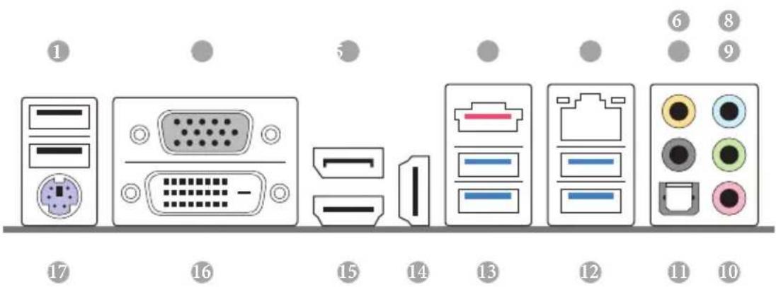
I/O Panel
No. Description No. Description
1 USB 2.0 Ports (USB01) 10 Microphone (Pink)
2 VGA Port 11 Optical SPDIF Out Port
3 Display Port 12 USB 3.0 Ports (USB3_23)
4 eSATA Connector***
13 USB 3.0 Ports (USB3_01)
5 LAN RJ-45 Port* 14 HDMI-In Port
6 Central / Bass (Orange) 15 HDMI-Out Port
7 Rear Speaker (Black) 16 DVI-D Port
8 Line In (Light Blue)
17 PS/2 Mouse/Keyboard Port
9 Front Speaker (Lime)**
- There are two LEDs on each LAN port. Please refer to the table below for the LAN port LED indications.
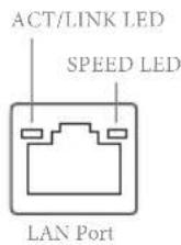
| Activity / Link LED Speed LED | |||
| Status Description Status Description | |||
| Off No Link Off | 10Mbps connection | ||
| Blinking | Data Activity | Orange | 100Mbps connection |
| On Link Green | Gbps connection | ||
** If you use a 2-channel speaker, please connect the speaker's plug into "Front Speaker Jack". See the table below for connection details in accordance with the type of speaker you use.
| Audio Output Channels | Front Speaker (No. 9) | Rear Speaker (No. 7) | Central / Bass (No. 6) | Line In (No. 8) |
| 2 V -- -- | ||||
| 4 V V -- -- | ||||
| 6 V V V -- | ||||
| 8 V V V V |

To enable Multi-Streaming, you need to connect a front panel audio cable to the front panel audio header. After restarting your computer, you will find the "Mixer" tool on your system. Please select "Mixer ToolBox", click "Enable playback multi-streaming", and click "ok". Choose "2CH", "4CH", "6CH", or "8CH" and then you are allowed to select "Realtek HDA Primary output" to use the Rear Speaker, Central/Bass, and Front Speaker, or select "Realtek HDA Audio 2nd output" to use the front panel audio.
*** The eSATA connector supports SATA with cables within 1 meters.
1 Introduction
Thank you for purchasing ASRock Z87 Extreme4 motherboard, a reliable motherboard produced under ASRock's consistently stringent quality control. It delivers excellent performance with robust design conforming to ASRock's commitment to quality and endurance.

Because the motherboard specifications and the BIOS software might be updated, the content of this documentation will be subject to change without notice. In case any modifications of this documentation occur, the updated version will be available on ASRock's website without further notice. If you require technical support related to this motherboard, please visit our website for specific information about the model you are using. You may find the latest VGA cards and CPU support list on ASRock's website as well. ASRock website http://www.asrock.com.
1.1 Package Contents
ASRock Z87 Extreme4 Motherboard (ATX Form Factor)
ASRock Z87 Extreme4 Quick Installation Guide
ASRock Z87 Extreme4 Support CD
4 x Serial ATA (SATA) Data Cables (Optional)
1 x I/O Panel Shield
1 x ASRock SLI_Bridge_2S Card
1.2 Specifications
| Platform | ATX Form Factor Premium Gold Capacitor design (100% Japan-made high-quality Conductive Polymer Capacitors) |
| A-Style | Home Cloud Purity Sound™ HDMI-In |
| CPU | Supports 4th Generation Intel® CoreTM i7 / i5 / i3 / Xeon® / Pentium® / Celeron® in LGA1150 Package Digi Power Design 12 Power Phase Design Supports Intel Turbo Boost 2.0 Technology Supports Intel K-Series unlocked CPU Supports ASRock BCLK Full-range Overclocking |
| Chipset | Intel® Z87 |
| Memory | Dual Channel DDR3 Memory Technology 4 x DDR3 DIMM slots Supports DDR3 2933+(OC)/2800(OC)/2400(OC)/2133(OC)/1866(OC)/1600/1333/1066 non-ECC, un-buffered memory Max. capacity of system memory: 32GB (see CAUTION) Supports Intel Extreme Memory Profile (XMP)1.3/1.2 Distortion-Free Slot |
| Expansion Slot | 3 x PCI Express 3.0 x16 slots (PCIE2/PCIE4/PCIE5: single at x16 (PCIE2); dual at x8 (PCIE2) / x8 (PCIE4); triple at x8 (PCIE2) / x4 (PCIE4) / x4 (PCIE5)) 2 x PCI Express 2.0 x1 slots 2 x PCI slots Supports AMD Quad CrossFireX™, 3-Way CrossFireX™ and CrossFireX™ Supports NVIDIA® Quad SLI™ and SLI™ |
Graphics
Intel® HD Graphics Built-in Visuals and the VGA outputs can be supported only with processors which are GPU integrated. Supports Intel® HD Graphics Built-in Visuals : Intel® Quick Sync Video with AVC, MVC (S3D) and MPEG-2 Full HW Encode1, Intel® InTru™ 3D, Intel® Clear Video HD Technology, Intel® Insider™, Intel® HD Graphics 4400/4600 Pixel Shader 5.0, DirectX 11.1 Max. shared memory 1792MB Four VGA Output options: D-sub, DVI-D, HDMI and DisplayPort Supports Triple Monitors Supports HDMI Technology with max. resolution up to 4K× 2K (4096x2304) @ 24Hz Supports DVI-D with max. resolution up to 1920x1200 @ 60Hz Supports D-Sub with max. resolution up to 1920x1200 @ 60Hz Supports DisplayPort with max. resolution up to 4K× 2K (4096x2304) @ 24Hz Supports Auto Lip Sync, Deep Color (12bpc), xvYCC and HBR (High Bit Rate Audio) with HDMI (Compliant HDMI monitor is required) Supports HDCP function with DVI-D, HDMI and DisplayPort ports Supports Full HD 1080p Blu-ray (BD) / HD-DVD playback with DVI-I, HDMI and DisplayPort ports
Audio
7.1 CH HD Audio with Content Protection (Realtek ALC1150
Audio Codec)
Premium Blu-ray audio support
Supports Purity SoundTM
- 115dB SNR DAC with differential amplifier
-TI"NE5532 Premium Headset Amplifier (supports up to
600 Ohms headsets)
Direct Drive Technology
EMI shielding cover
PCB isolate shielding
Supports DTS Connect
LAN
Gigabit LAN 10/100/1000 Mb/s
Giga PHY Intel° I217V
Supports Intel® Remote Wake Technology
Supports Wake-On-LAN
Supports Energy Efficient Ethernet 802.3az
Supports PXE
Rear Panel
I/O
1 x PS/2 Keyboard/Mouse Port
1xD-SubPort
1xDVI-DPort
1 x HDMI-Out Port
1 x HDMI-In Port
1xDisplayPort
1 x Optical SPDIF Out Port
1 x eSATA Connector
2xUSB2.0Ports
4xUSB3.0Ports
1 x RJ-45 LAN Port with LED (ACT/LINK LED and SPEED LED)
HD Audio Jack: Rear Speaker / Central / Bass / Line in / Front
Speaker / Microphone
Storage
6 x SATA3 6.0 Gb/s connectors by Intel® Z87, support RAID (RAID 0, RAID 1, RAID 5, RAID 10, Intel Rapid Storage Technology 12 and Intel Smart Response Technology), NCQ, AHCI and "Hot Plug" functions
2 x SATA3 6.0 Gb/s connectors by ASMedia ASM1061, support NCQ, AHCI and "Hot Plug" functions (SATA3_A0 connector is shared with eSATA port)
1 x eSATA connector by ASMMedia ASM1061, supports NCQ, AHCI, "Hot Plug" and Port Multiplier functions
| Connector | 1 x IR header 1 x COM port header 1 x Power LED header 2 x CPU Fan connectors (1 x 4-pin, 1 x 3-pin) 3 x Chassis Fan connectors (1 x 4-pin, 2 x 3-pin) 1 x Power Fan connector (3-pin) 1 x 24 pin ATX power connector 1 x 8 pin 12V power connector 1 x Front panel audio connector 3 x USB 2.0 headers (support 6 USB 2.0 ports) 1 x Vertical Type A USB 3.0 2 x USB 3.0 header (supports 4 USB 3.0 ports) (ASMedia Hub) 1 x Dr. Debug with LED 1 x Power Switch with LED 1 x Reset Switch with LED 1 x Clear CMOS Switch |
| BIOS Feature | 2 x 64Mb AMI UEFI Legal BIOS with Multilingual GUI support (1 x Main BIOS and 1 x Backup BIOS) Supports Secure Backup UEFI Technology ACPI 1.1 Compliance Wake Up Events SMBIOS 2.3.1 Support CPU, DRAM, PCH 1.05V, PCH 1.5V Voltage Multi-adjust-ment |
| Support CD | Drivers, Utilities, AntiVirus Software (Trial Version), Cyber- Link MediaEspresso 6.5 Trial, Google Chrome Browser and Toolbar, Start8, MeshCentral, Splashtop Streamer, Intel" Extreme Tuning Utility (IXTU) |
| Hardware Monitor | CPU/Chassis Temperature Sensing CPU/Chassis/Power Fan Tachometer CPU/Chassis Quiet Fan (Allow Chassis Fan Speed Auto- Adjust by CPU Temperature) CPU/Chassis Fan Multi-Speed Control Voltage Monitoring: +12V, +5V, +3.3V, CPU Vcore |
| OS | Microsoft* Windows* 8 / 8 64-bit / 7 / 7 64-bit compliant |
Certifications
FCC,CE,WHQL
ErP/EuP Ready (ErP/EuP ready power supply is required)
- For detailed product information, please visit our website: http://www.asrock.com

Please realize that there is a certain risk involved with overclocking, including adjusting the setting in the BIOS, applying Untied Overclocking Technology, or using third-party overclocking tools. Overclocking may affect your system's stability, or even cause damage to the components and devices of your system. It should be done at your own risk and expense. We are not responsible for possible damage caused by overclocking.

Due to limitation, the actual memory size may be less than 4GB for the reservation for system usage under Windows® 32-bit operating systems. Windows® 64-bit operating systems do not have such limitations. You can use ASRock XFast RAM to utilize the memory that Windows® cannot use.
1.3 Unique Features

ASRock A-Tuning
A-Tuning is ASRock's multi purpose software suite with a new interface, more new features and improved utilities, including XFast RAM, Dehumidifier, Good Night LED, FAN-Tastic Tuning, OC Tweaker and a whole lot more.

ASRock Instant Flash
ASRock Instant Flash is a BIOS flash utility embedded in Flash ROM. This convenient BIOS update tool allows you to update the system BIOS in a few clicks without preparing an additional floppy diskette or other complicated flash utility. Just save the new BIOS file to your USB storage and launch this tool by pressing <F6> or <F2> during POST to enter the BIOS setup menu to access ASRock Instant Flash. Please be noted that the USB flash drive or hard drive must use FAT32/16/12 file system.

ASRock APP Charger
Simply by installing the ASRock APP Charger makes your iPhone/iPad/iPod Touch charge up to 40% faster than before on your computer. ASRock APP Charger allows you to quickly charge many Apple devices simultaneously and even supports continuous charging when your PC enters into Standby mode (S1), Suspend to RAM (S3), hibernation mode (S4) or power off (S5).

ASRock XFast USB
ASRock XFast USB can boost the performance of your USB storage devices. The performance may depend on the properties of the device.

ASRock XFast LAN
ASRock XFast LAN provides faster internet access, which includes the benefits listed below. LAN Application Prioritization: You can configure your application's priority ideally and add new programs to the list. Lower Latency in Game: After setting online game's priority higher, it can lower the latency in games. Traffic Shaping: You can watch Youtube HD videos and download simultaneously. Real-Time Analysis of Your Data: With the status window, you can easily recognize which data streams you are currently transferring.

ASRock XFast RAM
ASRock XFast RAM is included in A-Tuning. It fully utilizes the memory space that cannot be used under Windows® 32-bit operating systems. ASRock XFast RAM shortens the loading time of previously visited websites, making web surfing faster than ever. And it also boosts the speed of Adobe Photoshop 5 times faster. Another advantage of ASRock XFast RAM is that it reduces the frequency of accessing your SSDs or HDDs in order to extend their lifespan.

ASRock Crashless BIOS
ASRock Crashless BIOS allows users to update their BIOS without fear of failing. If power loss occurs during the BIOS updating process, ASRock Crashless BIOS will automatically finish the BIOS update procedure after regaining power. Please note that BIOS files need to be placed in the root directory of your USB disk. Only USB 2.0 ports support this feature.

ASRock OMG (Online Management Guard)
Administrators are able to establish an internet curfew or restrict internet access at specified times via OMG. You may schedule the starting and ending hours of internet access granted to other users. In order to prevent users from bypassing OMG, guest accounts without permission to modify the system time are required.

ASRock Internet Flash
ASRock Internet Flash downloads and updates the latest UEFI firmware version from our servers for you without entering Windows OS. Please setup network configuration before using Internet Flash.

ASRock UEFI System Browser
ASRock System Browser shows the overview of your current PC and the devices connected.

ASRock Dehumidifier Function
Users may prevent motherboard damages due to dampness by enabling "Dehumidifier Function". When enabling Dehumidifier Function, the computer will power on automatically to dehumidify the system after entering S4/S5 state.

ASRock Easy RAID Installer
ASRock Easy RAID Installer can help you to copy the RAID driver from the support CD to your USB storage device. After copying the RAID driver to your USB storage device, please change "SATA Mode" to "RAID", then you can start installing the OS in RAID mode.

ASRock Easy Driver Installer
For users that don't have an optical disk drive to install the drivers from our support CD, Easy Driver Installer is a handy tool in the UEFI that installs the LAN driver to your system via an USB storage device, then downloads and installs the other required drivers automatically.
ASRock Interactive UEFI
ASRock Interactive UEFI is a blend of system configuration tools, cool sound effects and stunning visuals. The unprecedented UEFI provides a more attractive interface and more amusement.

ASRock Fast Boot
With ASRock's exclusive Fast Boot technology, it takes less than 1.5 seconds to logon to Windows 8 from a cold boot. No more waiting! The speedy boot will completely change your user experience and behavior.

ASRock Restart to UEFI
Windows* 8 brings the ultimate boot up experience. The lightning boot up speed makes it hard to access the UEFI setup. ASRock Restart to UEFI allows users to enter the UEFI automatically when turning on the PC. By enabling this function, the PC will enter the UEFI directly after you restart.

ASRock Good Night LED
ASRock Good Night LED technology offers you a better sleeping environment by extinguishing the unessential LEDs. By enabling Good Night LED in the BIOS, the Power/HDD LEDs will be switched off when the system is powered on. Good Night LED will automatically switch off the Power and Keyboard LEDs when the system enters into Standby/Hibernation mode as well.

ASRock USB Key
In a world where time is money, why waste precious time everyday typing usernames to log in to Windows? Why should we even bother memorizing those foot long passwords? Just plug in the USB Key and let your computer log in to windows automatically!

ASRock Home Cloud
This motherboard supports remote wake with the onboard Intel LAN, so you can connect with your PC from anywhere in the world. You will be able to power your PC on or turn it off, monitor and take control of it remotely with another smartphone, tablet or computer.
ASRock FAN-Tastic Tuning
ASRock FAN-Tastic Tuning is included in A-Tuning. Configure up to five different fan speeds using the graph. The fans will automatically shift to the next speed level when the assigned temperature is met.
ASRock Distortion-Free Slot
ASRock's new pin design for the memory slots and PCIe slots may appear to be the same as former designs, but actually effectively reduces distortion and promotes performance, because we strive for perfection even in the most trivial details.
Chapter 2 Installation
This is an ATX form factor motherboard. Before you install the motherboard, study the configuration of your chassis to ensure that the motherboard fits into it.
Pre-installation Precautions
Take note of the following precautions before you install motherboard components or change any motherboard settings.
Make sure to unplug the power cord before installing or removing the motherboard. Failure to do so may cause physical injuries to you and damages to motherboard components.
In order to avoid damage from static electricity to the motherboard's components, NEVER place your motherboard directly on a carpet. Also remember to use a grounded wrist strap or touch a safety grounded object before you handle the components.
Hold components by the edges and do not touch the ICs.
Whenever you uninstall any components, place them on a grounded anti-static pad or in the bag that comes with the components.
When placing screws to secure the motherboard to the chassis, please do not overtighten the screws! Doing so may damage the motherboard.
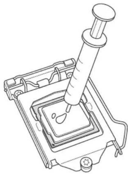
2.1 Installing the CPU

- Before you insert the 1150-Pin CPU into the socket, please check if the PnP cap is on the socket, if the CPU surface is unclean, or if there are any bent pins in the socket. Do not force to insert the CPU into the socket if above situation is found. Otherwise, the CPU will be seriously damaged.
- Unplug all power cables before installing the CPU.
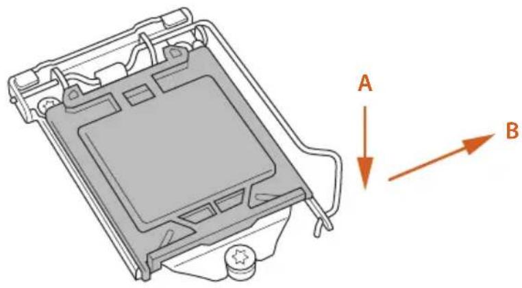
1
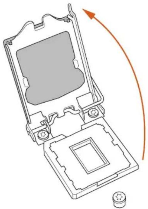
2
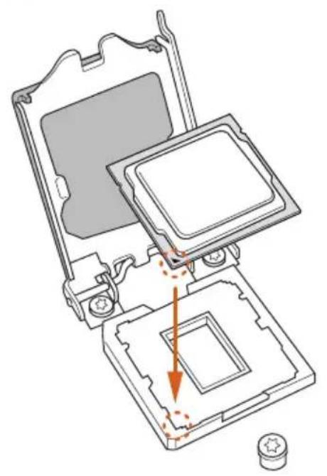
3
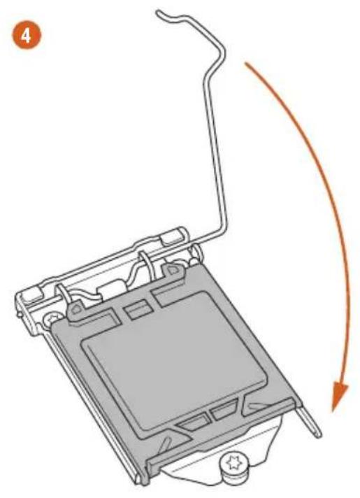
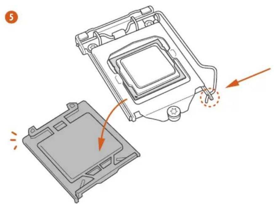

Please save and replace the cover if the processor is removed. The cover must be placed if you wish to return the motherboard for after service.
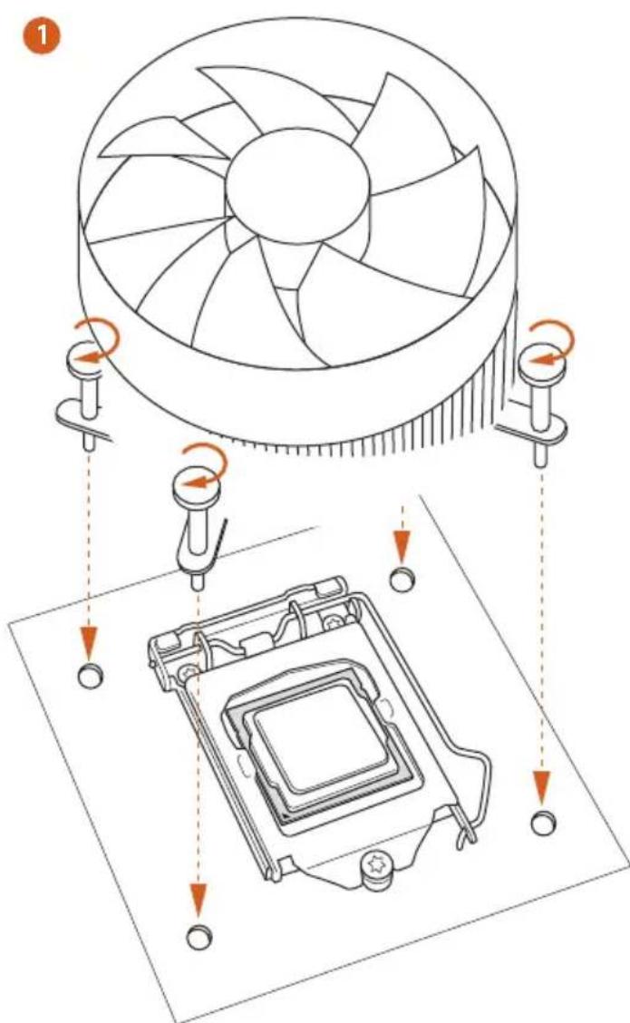
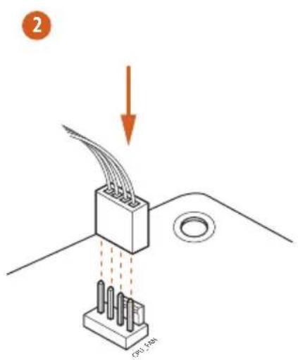
2.2 Installing the CPU Fan and Heatsink
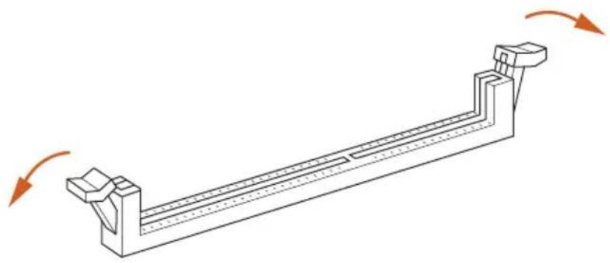
2.3 Installing Memory Modules (DIMM)
This motherboard provides four 240-pin DDR3 (Double Data Rate 3) DIMM slots, and supports Dual Channel Memory Technology.

- For dual channel configuration, you always need to install identical (the same brand, speed, size and chip-type) DDR3 DIMM pairs.
- It is unable to activate Dual Channel Memory Technology with only one or three memory module installed.
- It is not allowed to install a DDR or DDR2 memory module into a DDR3 slot; otherwise, this motherboard and DIMM may be damaged.
Dual Channel Memory Configuration
Priority DDR3_A1 DDR3_A2 DDR3_B1 DDR3_B2
| 1 Populated | Populated | |||
| 2 Populated | Populated | |||
| 3 Populated | Populated | Populated | Populated |

The DIMM only fits in one correct orientation. It will cause permanent damage to the motherboard and the DIMM if you force the DIMM into the slot at incorrect orientation.
1
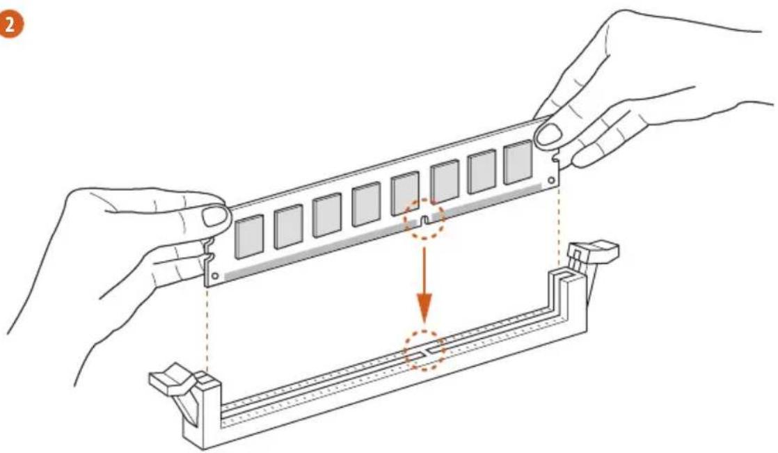
2
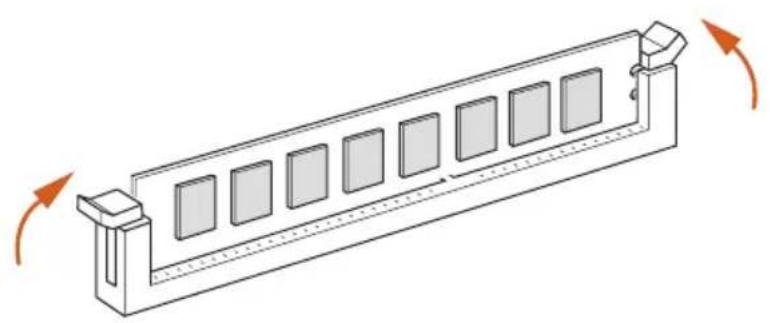
3
2.4 Expansion Slots (PCI and PCI Express Slots)
There are 2 PCI slots and 5 PCI Express slots on the motherboard.

Before installing an expansion card, please make sure that the power supply is switched off or the power cord is unplugged. Please read the documentation of the expansion card and make necessary hardware settings for the card before you start the installation.
PCI slot:
The PCI1 and PCI2 slot are used to install expansion cards that have 32-bit PCI interface.
PCIe slots:
PCIE1 (PCIe 2.0 x1 slot) is used for PCI Express x1 lane width cards.
PCIE2 (PCIe 3.0 x16 slot) is used for PCI Express x16 lane width graphics cards.
PCIE3 (PCIe 2.0 x1 slot) is used for PCI Express x1 lane width cards.
PCIE4 (PCIe 3.0 x16 slot) is used for PCI Express x8 lane width graphics cards.
PCIE5 (PCIe 3.0 x16 slot) is used for PCI Express x4 lane width graphics cards.
PCIe Slot Configurations
PCIE2 PCIE4 PCIE5
Single Graphics Card x16 N/A N/A
Two Graphics Cards in CrossFireXTM or SLI^TM Mode
x8x8N / A
Three Graphics Cards in 3-Way CrossFireXTM Mode
x8 x4 x4

For a better thermal environment, please connect a chassis fan to the motherboard's chassis fan connector (CHA_FAN1, CHA_FAN2 or CHA_FAN3) when using multiple graphics cards.
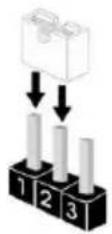
2.5 Jumpers Setup
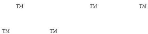
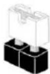
The illustration shows how jumpers are setup. When the jumper cap is placed on the pins, the jumper is "Short". If no jumper cap is placed on the pins, the jumper is "Open". The illustration shows a 3-pin jumper whose pin1 and pin2 are "Short" when a jumper cap is placed on these 2 pins.
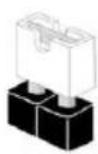
Short
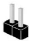
Open
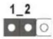
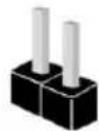
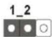
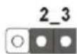
Clear CMOS Jumper (CLRCMOS1)
(see p.1, No. 17)
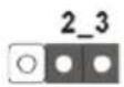
Clear CMOSDefault
CLRCMOS1 allows you to clear the data in CMOS. To clear and reset the system parameters to default setup, please turn off the computer and unplug the power cord from the power supply. After waiting for 15 seconds, use a jumper cap to short pin2 and pin3 on CLRCMOS1 for 5 seconds. However, please do not clear the CMOS right after you update the BIOS. If you need to clear the CMOS when you just finish updating the BIOS, you must boot up the system first, and then shut it down before you do the clear-CMOS action. Please be noted that the password, date, time, and user default profile will be cleared only if the CMOS battery is removed.

The Clear CMOS Switch has the same function as the Clear CMOS jumper.
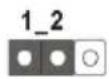
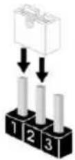
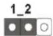
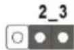
BIOS Selection Jumper
(BIOS_SEL1)
(see p.1, No. 16)
Default
(Main BIOS)
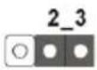
Backup BIOS
This motherboard has two BIOS onboard, a main BIOS (BIOS_A) and a backup BIOS (BIOS_B), which enhances protection for the safety and stability of your system. Normally, the system works on the main BIOS. However, if the main BIOS is corrupted or damaged, please use a jumper cap to short pin2 and pin3, then the backup BIOS will take over on the next system boot. After that, short pin1 and pin2 again, then use "Secure Backup UEFI" in the UEFI Setup Utility to duplicate a working copy of the BIOS files to the primary BIOS to ensure normal system operation. For safety issues, users are not able to update the backup BIOS manually. Users may refer to the BIOS LEDs (BIOS_A_LED or BIOS_B_LED) to identify which BIOS is currently activated.
2.6 Onboard Headers and Connectors

Onboard headers and connectors are NOT jumpers. Do NOT place jumper caps over these headers and connectors. Placing jumper caps over the headers and connectors will cause permanent damage to the motherboard.
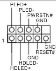
System Panel Header (9-pin PANEL1) (see p.1, No. 22)
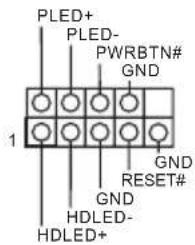
Connect the power switch, reset switch and system status indicator on the chassis to this header according to the pin assignments below. Note the positive and negative pins before connecting the cables.

PWRBTN (Power Switch):
Connect to the power switch on the chassis front panel. You may configure the way to turn off your system using the power switch.
RESET (Reset Switch):
Connect to the reset switch on the chassis front panel. Press the reset switch to restart the computer if the computer freezes and fails to perform a normal restart.
PLED (System Power LED):
Connect to the power status indicator on the chassis front panel. The LED is on when the system is operating. The LED keeps blinking when the system is in S1/S3 sleep state. The LED is off when the system is in S4 sleep state or powered off (S5).
HDLED (Hard Drive Activity LED):
Connect to the hard drive activity LED on the chassis front panel. The LED is on when the hard drive is reading or writing data.
The front panel design may differ by chassis. A front panel module mainly consists of power switch, reset switch, power LED, hard drive activity LED, speaker and etc. When connecting your chassis front panel module to this header, make sure the wire assignments and the pin assignments are matched correctly.
| Power LED Header (3-pin PLED1) (see p.1, No. 21) | PLED+PLED+ | Please connect the chassis power LED to this header to indicate the system's power status. |
| Serial ATA3 Connectors (SATA3_0_1: see p.1, No. 12) (SATA3_2_3: see p.1, No. 13) (SATA3_4_5: see p.1, No. 14) (SATA3_A0_A1: see p.1, No. 11) | SATA3_0_1SRA8345_8A7A3 | These eight SATA3 connectors support SATA data cables for internal storage devices with up to 6.0 Gb/s data transfer rate. If the eSATA port on the rear I/O has been connected, the internal SATA3_A0 will not function. To minimize the boot time, use Intel® Z87 SATA ports (SATA3_0) for your bootable devices. |
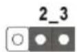
| USB 2.0 Headers (9-pin USB2_3) (see p.1, No. 23) (9-pin USB4_5) (see p.1, No. 24) (9-pin USB6_7) (see p.1, No. 25) | USB_PWR P+GND DUMMY 1 GND P+USB_PWR | Besides two USB 2.0 ports on the I/O panel, there are three headers on this motherboard. Each USB 2.0 header can support two ports. |
| USB 3.0 Headers (19-pin USB3_4_5) (see p.1, No. 8) (19-pin USB3_6_7) (see p.1, No. 9) | Vbus Vbus IntA_PA_SSRX-IntA_PA_SSRX+IntA_PA_SSRX+GNDIntA_PA_SSTX-IntA_PA_SSTX+IntA_PA_SSTX+GNDIntA_PA_D-IntA_PA_D+IntA_PA_D+Dummy | Besides four USB 3.0 ports on the I/O panel, there are one header on this motherboard. Each USB 3.0 header can support two ports. |
| (USB3_8) (see p.1, No. 10) |
Front Panel Audio Header
(9-pin HD_AUDIO1)
(see p.1, No. 29)
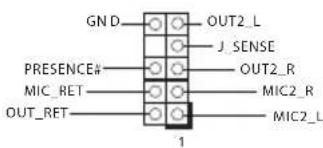
This header is for connecting audio devices to the front audio panel.

- High Definition Audio supports Jack Sensing, but the panel wire on the chassis must support HDA to function correctly. Please follow the instructions in our manual and chassis manual to install your system.
- If you use an AC'97 audio panel, please install it to the front panel audio header by the steps below:
A. Connect Mic_IN (MIC) to MIC2_L.
B. Connect Audio_R (RIN) to OUT2_R and Audio_L (LIN) to OUT2_L.
C. Connect Ground (GND) to Ground (GND).
D. MIC_RET and OUT_RET are for the HD audio panel only. You don't need to connect them for the AC'97 audio panel.
E. To activate the front mic, go to the "FrontMic" Tab in the Realtek Control panel and adjust "Recording Volume".
Chassis Speaker Header
(4-pin SPEAKER1)
(see p.1, No. 15)
DUMMY SPEAKER
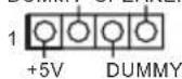
Please connect the chassis speaker to this header.
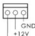
Chassis and Power Fan
Connectors
(4-pin CHA_FAN1)
(see p.1, No. 26)
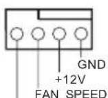
FAN_SPEED_CONTROL
Please connect fan cables to the fan connectors and match the black wire to the ground pin.
(3-pin CHA_FAN2)
(see p.1, No. 2)
(3-pin CHA_FAN3)
(see p.1, No. 31)
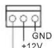
FAN_SPEED
(3-pin PWR_FAN1)
(see p.1, No. 30)
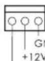
PWR_FAN_SPEED
| CPU Fan Connectors (4-pin CPU_FAN1) (see p.1, No. 3) | FAN_SPEED_CONTROL FAN_SPEED +12V GND | This motherboard pro- vides a 4-Pin CPU fan (Quiet Fan) connector. If you plan to connect a 3-Pin CPU fan, please connect it to Pin 1-3. |
| (3-pin CPU_FAN2) (see p.1, No. 4) | FAN_SPEED +12V GND | |
| ATX Power Connector (24-pin ATXPWR1) (see p.1, No. 7) | 12 1 24 13 | This motherboard pro- vides a 24-pin ATX power connector. To use a 20-pin ATX power supply, please plug it along Pin 1 and Pin 13. |
| ATX 12V Power Connector (8-pin ATX12V1) (see p.1, No. 1) | 1 4 5 8 | This motherboard pro- vides an 8-pin ATX 12V power connector. To use a 4-pin ATX power supply, please plug it along Pin 1 and Pin 5. |
| Infrared Module Header (5-pin IRI) (see p.1, No. 28) | IRTX +5VSB DUMMY 1 GND RRX | This header supports an optional wireless transmitting and receiving infrared module. |
| Serial Port Header (9-pin COM1) (see p.1, No. 27) | RRXD1 DDTR#1 DDS#1 CCTS#1 1 1 1 RRI#1 RRTS#1 GND TTXD1 DDCD#1 | This COM1 header supports a serial port module. |
2.7 Smart Switches
The motherboard has three smart switches: Power Switch, Reset Switch and Clear CMOS Switch, allowing users to quickly turn on/off the system, reset the system or clear the CMOS values.
Power Switch
(PWRBTN)
(see p.1, No. 18)
Power Switch allows users to quickly turn on/off the system.
Reset Switch
(RSTBTN)
(see p.1, No. 19)

Reset Switch allows users to quickly reset the system.
Clear CMOS Switch
(CLRCBTN)
(see p.1, No. 20)
Clear CMOS Switch allows users to quickly clear the CMOS values.

This function is operational only when you power off your computer and unplug the power supply.
1 Einleitung
- Extreme Memory Profile (XMP)1.3/1.2
Erweiter-
ungststeck-
(OC)/1866(OC)/1600/1333/1066
AVERTISSEMENT)
- Extreme Memory Profile (XMP)1.3/1.2
Fente
d'expansion
mode x16 (PCIE2); double en mode x8 (PCIE2) / x8 (PCIE4); triple en mode x8 (PCIE2) / x4 (PCIE4) / x4 (PCIE5))
TM,3-Way
CrossFireX™ et CrossFireX™
TM et SLI TM
Graphiques
Visuals: Intel Quick Sync Video with AVC, MVC (S3D) and MPEG-2 Full HW Encode1, Intel InTru™ 3D, Intel Clear Video HD Technology, Intel Inside™, Intel HD Graphics 4400/4600
DisplayPort
maximale de 4K× 2K (4096x2304) @ 24Hz
de 1920x1200@60Hz
de 1920x1200@60Hz
maximale de 4K× 2K (4096x2304) @ 24Hz
| Chipset | Z87 |
| Memoria | |
| (OC)/1866(OC)/1600/1333/1066 non-ECC, un-buffered | |
| riferimento a ATTENZIONE) | |
| *Extreme Memory Profile (XMP)1.3/1.2 |
| Slot di espansione | a x16 (PCIE2); doppio a x8 (PCIE2) / x8 (PCIE4); tripl0 a x8 (PCIE2) / x4 (PCIE4) / x4 (PCIE5)) |
| TM, 3-Way CrossFireXTM and CrossFireXTM | |
| TM e SLI™ |
Grafica
(RAID 0, RAID 1, RAID 5, RAID 10, Intel Rapid Storage Technology 12 e Intel Smart Response Technology), NCQ, AHCI e funzioni "Hot Plug"
IyMOJuaHnIO (OCHOBHaBIOS)
PesepbHbI BIOS
3Ta MaTePnHcKaI IlaTa cHa6KeHa IByMa BIOS - OCHOBHOI BIOS (BIOS_A) IN BIOS pe3epBHOrO KOIIPOBaHNrA (BIOS_B), - YTO IOBbIIaEaT yPoBeHb 3aIIITbI IN CTa6NJIbHOCTn pa6OTbI CnCTeMb. O6bYHO CnCTeMa IcIOJIb3YeT OCHOBHyIO BIOS. IIINOBpeKJHeHH nIIN C6OE OCHOBHOI BIOS KOIIaUKOBOI IepMbUKOH 3AMKHHTe KOHTAKT 2 IN KOHTAKT 3, IN CIEyIOII INpe3aIpyck CnCTeMbI 6yIDET OcyIeCTBJeH C NIOJIb3OBAHHeM pe3epBHOI BIOS. IocIe 3TOI0 OIIaTb 3AMKHHTe KOHTAKT 1 IN KOHTAKT 2 IN BYTNIte HAcTpOKn UEFI IcIOJIb3yIte OIIIO Secure Backup UEFI, YTO6bIBblIOIHHTb KOIIPOBaHHe pa6OuHX φaIIIOB BIOS B OCHOBHyIO BIOS IIIN ObecIeHnH 6eOIIaCHOCTHpyHoe o6HOBJIeHne pe3epBHOI KOIIIN BIOS IIIOJIb3OBATeJIeM OTKIOueHo. OIIpeJIeNTb, KaKaI BIOS IcIOJIb3yeTcB HAcToIeE BpeM, MOKHO IIO CBETOIOIHOM INIINKaTopaM BIOS (BIOS_A_LED INIIN BIOS_B_LED).
1.4 Kolodkn pa3bembl, pacnoIooKeHHbIe Ha MaTePnHcKo INaTe

Pacnojokenhhe Ha Mamepuhckoi nname konodku u pa3bemynepebukamu HE aomc. HE ycmahanabuaime Ha 3mu konodku u pa3bemykonnauckoible nepembu. Ycmanobka konnaukobbx nepbuek ha 3mu konodku u pa3bemy MOKem b13bamb Heycmpaumoe nopekdeHue Mamepuhckoi nnmbi.
KoIOnKa cNCTeMHoH IaHeHn (9-KoHTaKTHa, PANEL1) (CM. cTp. 1, No 22)
IIOKIOUHTe
pacnoIOXKeHHbIe Ha
KOpIIyCe BbIKIOuTeJIb
HITaHn, KHOINKy
Ipe3aRpy3KN H
HINIKKaTOP COCTOHNH
CNCTeMBI K 3TOI KOIOJKe
B COOTBeTCTBmC
paIpeJeIeHNEM
KOHTaKTOB,
IPNBHeEHbIM HNKe.
IpeE IOkIOUeHNem
Ka6eIe OIIpeJIte
IOLOXKeJIbHbI
IOPTNUaTeJIbHbI
KOHTaKTbl.

PWRBTN (Khonka numahan):
Hodknouhene Knonku numanu, pacnnojooenho ha nepeohne nahenu Kopnyca. MoKHO nacmpounb nopdoK bkknouenucmembu cunonbsobahuem Khonku numanu.
RESET (Khonka nepe3a2py3ku):
IIOKKnouHHe KhONku nepe3aepy3ku cucmemb, pacnoNoKeHHoHa nepeDHei naHenu Kopnyca. HAnKmune KhONky nepe3aepy3ku, umobu nepe3anycumbk Komnbomep, eCu OH 3aBuc u HopMaNbbl 3anyck Heo3MoKeH.
PLED (cbemoduoohn udukamop numanu cucmembi):
Iodknouene unukamopa ccmnna, pacnonokennozo ha nepedne na henu kopnyca. Cbemoduohn uhdukamop zopum, kozda cucmema pabomaem. Kozda cucmema haxodumc 6 pekume okuhan S1/S3, cbemoduod muaem. Kozda cucmema haxodumc 6 pekume okuhan S4 uu bkvloueha (S5), cbemoduod ne zopum.
HDLED (ceemoduodhuiundukamoppaobmkeecmkzoouka):
Iodknouhenue cbemoduohzo undukamopa paobmbj kecmko zo dcca, pacnoiokeHHo na nepeohne naneu Cbemoduohbui uhdukamop zopum, kozda kecmku duck bblnoHnem cunmbaue uuu 3anuc dbHHbx.
Ipeodnnaenb moem sbmb pa3no ha pa3hoxk Kopnycx. B ochobom nepeohnaenb 6knouaem b cebn knonky numanu, knonky nepe3aepy3ku, cbeoduoohn uhoekamop numanu, cbeoduoohn uudukamop pabombkecmko2o ducka, duamuk u m. d. Ppu nodknoeenu nepedneu naheu K emou konolokne npabunbo nodknouaume npoboda K konmakmam.
(3-KoHTaKTbI, PWR_FAN1)
(CM. cTp. 1, N° 30)
PWR_FAN_SPEED
| Ра3ьемы BeHTиЯTopов IПI (4-КонТаКтний, CPU_ FAN1) (Cm.ст. 1, № 3) | FAN_SPEED_CONTROL FAN_SPEED +12V GND | Фanta Материнская Плata снабжени 2 1 Ф�я малюшушино БеHTиЯTopа IПI.Если ВИ собираетсь пОдкlioочпь 3-КоНТаКтний ВeHTиЯTop oxлajждиenv Прочesscopa, пОдкlioочи ero K KOнТаКтам 1-3. |
| (3-КонТаКтний, CPU_ FAN2) (Cm.ст. 1, № 4) | FAN_speed +12V GND | |
| Ра3ьем пітань ATX (24-КонТаКтний, ATXPWR1) (Cm.ст. 1, № 7) | 12 1 13 | Фanta Материнская Плata снабжени 24-КонТаКтньIM pa3ьемOM Пітань ATX. Чтоб IMСПОЛБЗОВАТь 20-КонТаКтний pa3ьем пітань ATX, ПОДКlioочпte erO BДОЛь КонТаКтам 1 и КОнТаКтам 13. |
| Ра3ьем пітань ATX 12 B (8-КонТаКтний, ATX12V1) (Cm.ст. 1, № 1) | 1 5 8 | Фanta Материнская Плata снабжени 8-КонТаКтньIM pa3ьемOM Пітань ATX 12 B.Чтоб IMСПОЛБЗОВАТь 4-КонТаКтний pa3ьем пітань ATX, ПОДКlioочпte erO BДОЛь КонТаКтам 1 и КОнТаКтам 5. |
| Колода Инфрарас Horo MOДУЛA (5-КонТаКтнay, IR1) (Cm.ст. 1, № 28) | IRTX +5VSB DUMMY 1 GND IRRX | |
| Колода Инфрарас Horo Порта (9-КонТаКтнay, COM1) (Cm.ст. 1, № 27) | RRXD1 DDTR#1 DDS#1 CCTS#1 1 RR#1 GND TTXD1 DDCD#1 | Фanta КОлдka ПОддержИвael ДОпОЛнITEьнHuO 6ecПロВОДнHuO поредчу и п佩em сИГнадь ИнфрарасHoro MOДУЛA. Колдka COM1 ПОддержИвael ПОдд�чeurne МОДУЛA ПОслдоваTeььHOrO Порта. |
1.5 ΘneKtpoHHbIe KHOpKN
MaTePnHcKa IIaTa CHa6KeHa TpeM 3JIeKTPoHHbIMN KHOIIKaMn: KHOIIKa IIrTaHn, KHOIIKa Ipe3aRpy3Kn HpeKIIIOuAteIb c6poca HAcTpoek CMOS, IIpeHa3HaueHHbIMn IJIg 6bICTPOTO BKIOUeHn/ BbIKIOUeHn CNCTeMbI, Ipe3aRpy3Kn CNCTeMbI N O6HyIeHn 3HaueHn CMOS.
KhoIIka\PHTaHnA (PWRBTN)
(CM. ctp. 1, N° 18)
KhoIIKa IIITaHnIa
IpeHa3NaYeHa IJIa
6bICTPORO BKNIOUOeHnI/
BbIKHIOUeHN CnCTeMbI.
KhoIIka Ipepe3aIpy3KN (RSTBTN)
(CM. ctp. 1, N° 19)

KhoIIkaIpe3arpy3kn IpeHa3NaueHa nn
6bICTpoI Ipepe3aIpy3KN CNTEmbl.
KhoIIka c6poca hactpoek CMOS
(CLRCBTN)
(CM. cTp. 1, N° 20)
KhoIIKa c6pOca HAcTpoeK CMOS IIpeHa3NaueHa ⅡIa 6bICTpOo 06HyJIeHnIa HaueHn CMOS.

3ma fynkua pa6omaem moIbko, ecnu numanur konmbiomepa buknoe u on omknouen om cemu numanur.
1 Introdução
PWRBTN (Güç Anahtar):
Extreme Memory Profile (XMP)1.3/1.2
音长
@ x16 (PCIE2), @ x8 (PCIE2) / x8 (PCIE3), @ x8
(PCIE2) / x4 (PCIE4) / x4 (PCIE5))
TM,3-Way CrossFireXTM
CrossFireX™ 起到
Vertical Type A USB 3.0
2 x USB 3.0 header (supports 4 USB 3.0 ports) (ASMedia Hub)
BIOS
BIOS1 内部映像BIOS1)
Ji
CyberLink MediaEspresso 6.5 Interoper, Google Chrome BrLaUerJIeTbBa, Start8, MeshCentral, Splashtop Streamer, Intel
hur
图
OS
在
*中国海国音国自

CMOSJUWIGS WTOI CMOS

i

1.1 ロックーダの内容
1.2仕樣

TM
TM
4400/4600
DisplayPort
24Hz
LAN
x Vertical Type A USB 3.0
(ASMedia Hub)
os


1.3 ヨンハ一設定
Short
Open
(CLRCMOS1)


(BIOS_SEL1)
- Extreme Memory Profile (XMP)1.3/1.2
扩充槽
(PCIE2):双-x8(PCIE2)/x8(PCIE4):三-x8(PCIE2)/x4
(PCIE4) / x4 (PCIE5))
TM、3向CrossFireXTM和
CrossFireX™
TM和 SLI^TM
图形
效和 VGA 输出。
用AVC、MVC(S3D)和MPEG-2 Full HW Encode1、Intel*InTtuTM 3D、IntelClear Video HD技术、IntelInsiderTM、Intel*HD Graphics4400/4600
DisplayPort
(4096x2304)
(4096x2304)
x Vertical Type A USB 3.0
(ASMedia Hub)
BIOS功能特点
x主BIOS和1x备份BIOS)
(Voltage Multi-adjustment)
支持光盘
MediaEspresso 6.5 试用版、Google Chrome 浏览器和工具栏、Start8、MeshCentral、Splashtop Streamer、Intel
硬件监控
扇速度)
操作系统
认证
^a K-Series unlocked CPU
晶片組
Z87
配體
Extreme Memory Profile (XMP)1.3/1.2
扩充插槽
(PCIE2);雙x8(PCIE2)/x8(PCIE4);三x8(PCIE2)/x4
(PCIE4) / x4 (PCIE5))
CrossFireX™
TM、3-Way CrossFireXTM 及
TM 及 SLI
顯示卡
x Vertical Type A USB 3.0
(ASMedia Hub)
BIOS功能
x主BIOSand1x備用BIOS)
支援CD
MediaEspresso 6.5 Trial、Google Chrome 測覽器及工具列、Start8、MeshCentral、Splashtop Streamer、Intel
硬體監視器
風扇速度)
作業系統
認證
Extreme Memory Profile (XMP)1.3/1.2
Slot Ekspansi
x16 (PCIE2); sua pada x8 (PCIE2) / x8 (PCIE3); tiga pada x8 (PCIE2) / x4 (PCIE4) / x4 (PCIE5))
dan CrossFireX™
TM,3-Way CrossFireXTM
TM dan SLI TM
Grafis
Clear CMOS Jumper (CLRCMOS1)
(lihathal.1,No.17)
Clear CMOSDefault
RESET (Switch Atur Ulang):
If you need to contact ASRock or want to know more about ASRock, you're welcome to visit ASRock's website at http://www.asrock.com; or you may contact your dealer for further information. For technical questions, please submit a support request form at http://www.asrock.com/support/tsd.asp
ASRock Incorporation
2F., No.37, Sec. 2, Zhongyang S. Rd., Beitou District,
Taipei City 112, Taiwan (R.O.C.)
ASRock EUROPE B.V.
Bijsterhuizen 3151
6604 LV Wijchen
The Netherlands
Phone: +31-24-345-44-33
Fax: +31-24-345-44-38
ASRock America, Inc.
13848 Magnolia Ave, Chino, CA91710
U.S.A.
Phone: +1-909-590-8308
Fax: +1-909-590-1026
For the following equipment:
Motherboard
(Product Name)
Z87 Extreme4 / ASRock
(Model Designation / Trade Name)
ASRock Incorporation
(Manufacturer Name)
2F., No.37, Sec. 2, Zhongyang S. Rd., Beitou District, Taipei City 112, Taiwan (R.O.C.)
(Manufacturer Address)
is herewith confirmed to comply with the requirements set out in the Council
Directive on the Approximation of the Laws of the Member States relating to
Electromagnetic Compatibility Directive (2004/108/EC) and Safety Directive (2006/95/ EC), the following standards are applied:
EN 55022: 2006+A1:2007
EN61000-3-2:2009
EN61000-3-3:2008
EN 55024:1998 + A1:2001 + A2:2003
IEC 61000-4-2: 2008;
IEC 61000-4-3:2010; IEC 61000-4-4:2010
IEC 61000-4-5:2005; IEC 61000-4-6:2008
IEC 61000-4-8:2009;IEC 61000-4-11:2004
EN 60950-1:2005 + A1:2009
IEC 60950-1:2006 + A11:2009 + A1:2010 + A12:2011
The following manufacturer / importer or authorized representative established within the EUT is responsible for this declaration:
ASRock EUROPE B.V.
(Company Name)
Bijsterhuizen 3151 6604 LV Wijchen The Netherlands
(Company Address)
Person responsible for making this declaration:

(Name, Surname)
A.V.P
(Position / Title)
Apr. 26, 2013
(Date)