OSMOSE N°880115 - Pool TRIGANO - Free user manual and instructions
Find the device manual for free OSMOSE N°880115 TRIGANO in PDF.
| Product type | Oval above-ground pool |
| Brand | Trigano |
| Model | OSMOSE N°880115 |
| Outer dimensions (coping) | 5.15 x 3.90 m / 6.35 x 3.90 m / 7.60 x 3.90 m / 7.90 x 4.85 m / 9.40 x 4.85 m |
| Wall dimensions | 4.85 x 3.60 m / 6.10 x 3.60 m / 7.30 x 3.60 m / 7.60 x 4.60 m / 9.20 x 4.60 m |
| Pool height | 1.32 m |
| Available colors | Anthracite / Brown |
| Water volume | 19 m³ / 24 m³ / 29 m³ / 37 m³ / 45 m³ depending on size |
| Wall material | Steel with anti-corrosion coating |
| Liner material | Reinforced PVC (thickness not specified) |
| Filtration capacity | 4 m³/h / 6 m³/h / 8 m³/h / 10 m³/h / 12 m³/h depending on size |
| Daily filtration time | 3h15 to 6h depending on size and flow rate |
| Filtration system | Sand filter or Aqualoon balls filter (supplied separately) |
| Included equipment | Wall, liner, ladder, filtration system, skimmer, coping, screws |
| Recommended ground mat | Geotextile felt (not provided in some kits) |
| Ground preparation | Flat, hard, level ground (max 2 cm difference) |
| Number of people for assembly | 2 adults minimum |
| Estimated assembly time | Approximately 2 days excluding ground work and filling |
| Ideal temperature for liner installation | Between 18°C and 25°C |
| Safety | Removable ladder, barrier, cover or fall detector recommended |
| Warranty | 2 years structure and accessories, 2 years liner (welding defects) |
Frequently Asked Questions - OSMOSE N°880115 TRIGANO
User questions about OSMOSE N°880115 TRIGANO
0 question about this device. Answer the ones you know or ask your own.
Ask a new question about this device
Download the instructions for your Pool in PDF format for free! Find your manual OSMOSE N°880115 - TRIGANO and take your electronic device back in hand. On this page are published all the documents necessary for the use of your device. OSMOSE N°880115 by TRIGANO.
USER MANUAL OSMOSE N°880115 TRIGANO
natural_image
Illustration of two large outdoor swimming pools with blue water, one with black walls and the other with wooden lattice stands (no text or symbols)FR 2
DE 20
ES 38
IT....56
NL....74
UK 92
OSMOSE
Ovale – Ovalform – Ovalada – Ovale – Ovaal – Oval
text_image
4.6m 7.6 x 4.6m 6.1m 7.6m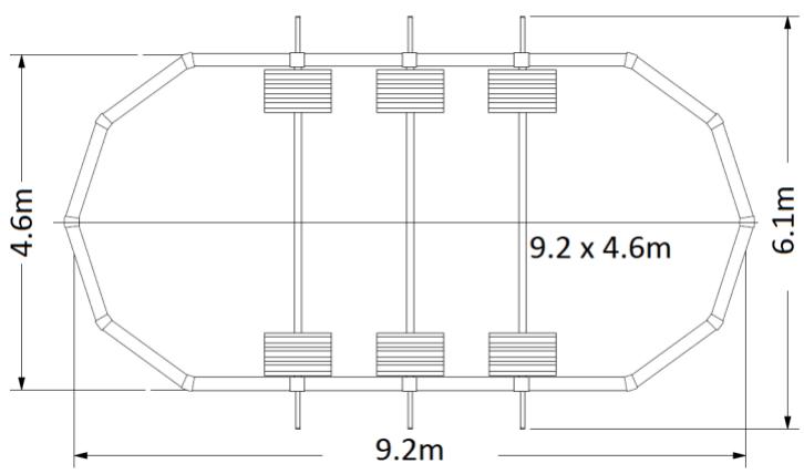
text_image
4.6m 9.2 x 4.6m 6.1m 9.2mother
| Dimension | Value | | --------- | ----- | | Height | 7,32 | | Width | 3,61 | | Top Margin | R1,81 | | Bottom Margin | 0,62 | | Bottom Width | 1,24 | | Bottom Height | 1,24 | | Bottom Height | 0,62 | | Total Length | 3,71 | The labels for the top and bottom segments are 'R1.81' and 'R1.61', respectively. The values for the bottom segments are '0.62'.
other
| Dimension | Value | | --------- | ----- | | Total Length | 7,64 | | Height | 4,57 | | R2,29 Section | 0,77 | | R2,29 Section (Top) | 1,53 | | R2,29 Section (Bottom) | 0,77 | | Total Width | 3,07 | | Total Height | 0,77 | | Total Width | 1,53 | | Total Height | 0,77 |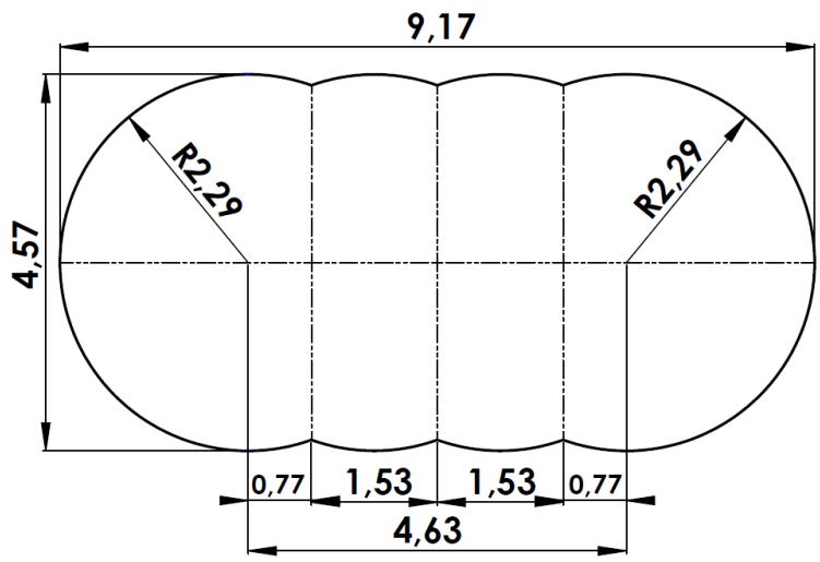
other
| Dimension | Value | | --------- | ----- | | Total Length | 9,17 | | Height | 4,57 | | Top Margin | R2,29 | | Middle Margin | 0,77 | | Bottom Margin | 1,53 | | Top Margin | 1,53 | | Bottom Margin | 0,77 | | Total Width | 4,63 |other
| Dimension | Value | | --------------- | ------- | | Top Width | 5.15x3.90m | | Top Height | 6.35x3.90m | | Top Height | 7.60x3.90m | | Top Height | 7.90x4.85m | | Top Height | 9.40x4.85m | | Bottom Width | 1.24m | | Bottom Height | 1.24m | | Bottom Height | 1.24m | | Bottom Height | 1.54m | | Bottom Height | 1.54m | | Middle Width | 30cm | | Middle Height | 48cm | | Middle Height | 137cm | | Middle Height | 89cm | | Middle Height | 15cm | | Middle Height | 30cm | | Bottom Height | 89cm |natural_image
Technical line drawing of a structural frame assembly with supports and mounting blocks (no text or symbols)text_image
mind. 30 cm5.2. Grundriss des Pools in Ovalform
text_image
4.6m 7.6 x 4.6m 6.1m 7.6m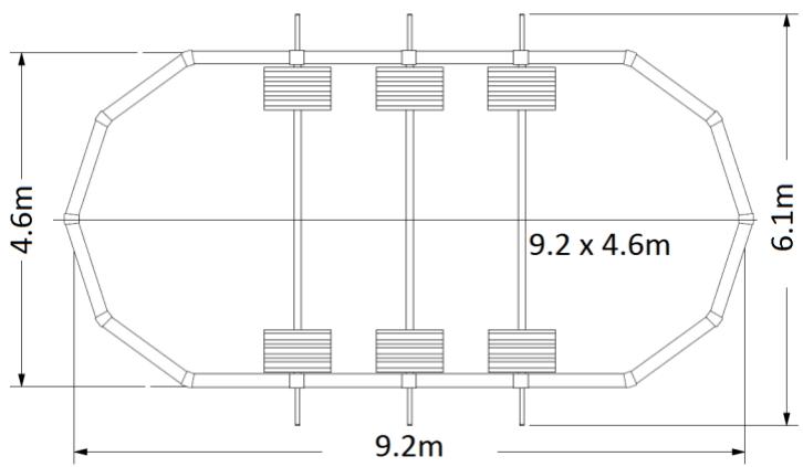
text_image
4.6m 9.2 x 4.6m 6.1m 9.2mnatural_image
Technical line drawing of a structural frame assembly with supports and mounting blocks (no text or symbols)text_image
4.6m 7.6 x 4.6m 6.1m 7.6m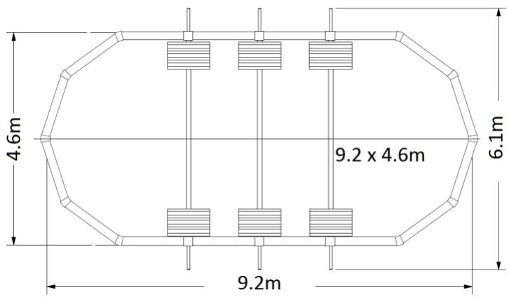
text_image
4.6m 9.2 x 4.6m 6.1m 9.2m5.3 Plano de la piscina ovalada
natural_image
Technical line drawing of a structural frame assembly with supports and mounting blocks (no text or symbols)text_image
Pared 10 cm Arena 5 cmtext_image
Mal Liner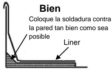
text_image
4.6m 7.6 x 4.6m 6.1m 7.6m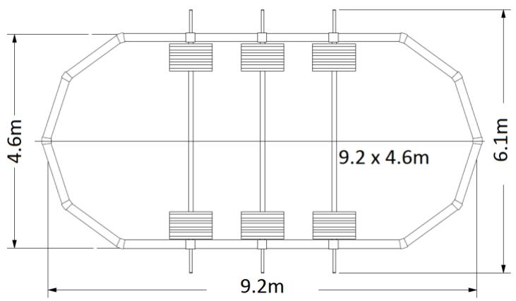
text_image
4.6m 9.2 x 4.6m 6.1m 9.2mother
| Dimension | Value | | --------- | ----- | | Height | 7,32 | | Width | 3,61 | | Top Margin | R1,81 | | Bottom Margin | 0,62 | | Bottom Width | 1,24 | | Bottom Height | 1,24 | | Bottom Height | 0,62 | | Total Length | 3,71 | The labels for the top and bottom segments are 'R1.81' and 'R1.61', respectively. The values for the bottom segments are '0.62'.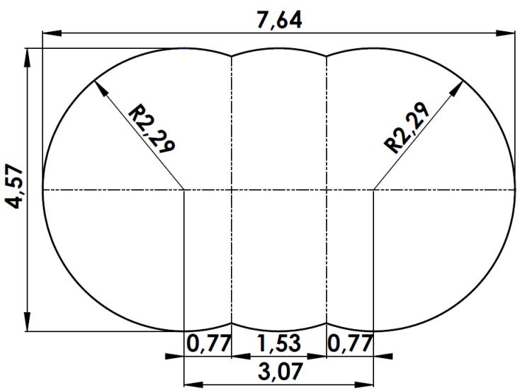
other
| Dimension | Value | | --------- | ----- | | Total Length | 7,64 | | Height | 4,57 | | R2,29 Width | 0,77 | | R2,29 Height | 1,53 | | R2,29 Width (Bottom) | 3,07 | | R2,29 Width (Top) | 0,77 |
other
| Dimension | Value | | --------- | ----- | | Total Length | 9,17 | | Height | 4,57 | | Top Margin | R2,29 | | Middle Margin | 0,77 | | Bottom Margin | 1,53 | | Top Margin | 1,53 | | Bottom Margin | 0,77 | | Total Width | 4,63 |natural_image
Technical line drawing of a structural frame assembly with supports and mounting blocks (no text or symbols)natural_image
Pure diagram of four vertical bars connected by dashed lines, labeled 'NO' at bottom (no text or symbols within diagram)text_image
4.6m 7.6 x 4.6m 6.1m 7.6m
text_image
4.6m 9.2 x 4.6m 6.1m 9.2mother
| Dimension | Value | | ----------------- | ------- | | Total Height | 6,35 x 3,90 m | | Total Height | 7,60 x 3,90 m | | Total Height | 7,90 x 4,85 m | | Total Height | 9,40 x 4,85 m | | Height (Left) | 6,35 x 3,90 m | | Height (Right) | 7,60 x 3,90 m | | Height (Center) | 7,90 x 4,85 m | | Height (Center) | 9,40 x 4,85 m | | Width (Left) | 6,35 x 3,90 m | | Width (Right) | 7,60 x 3,90 m | | Width (Center) | 7,90 x 4,85 m | | Width (Center) | 9,40 x 4,85 m | | Width (Center) | 1,24 m | | Width (Center) | 1,54 m | | Width (Center) | 1,54 m | | Width (Center) | 30cm | | Width (Center) | 48cm | | Width (Center) | 137cm | | Width (Center) | 15cm | | Width (Center) | 30cm | | Width (Center) | 89cm |natural_image
Technical line drawing of a structural frame assembly with supports and mounting blocks (no text or symbols)text_image
Fout Liner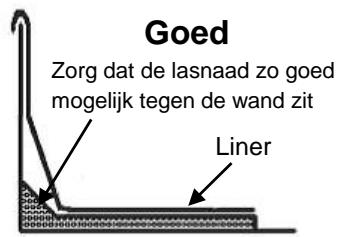
This article has been designed for family use outdoors under adult supervision. It may not be used under any circumstances for communal or public sites (schools, day care, parks, playgrounds...).
IMPORTANT
Please read this manual carefully and keep it for future reference. Similarly, the manuals for other components (skimmer, filter, etc.) should also be kept.
Assembly must be performed by adults (at least two people) following the preparation and assembly instructions (assembly should take one to two days excluding any earthwork and plumbing).
We suggest you assemble your ladder before assembling your pool (if your pool is equipped with a ladder).
Using a pool kit implies compliance with the safety instructions described in the maintenance manual and user guide.
Before assembling your pool, make any declarations (at the town hall for instance) and fulfil other requirements (such as taking out insurance) in order to obtain any authorisations for your project, for which you will be responsible.
WARNING
- Do not attempt installation in windy weather as the pool wall will be very difficult to handle.
- Properly tighten all screws. Inadequate tightening may cause structural failure.
- Handle the PVC liner carefully during assembly. Do not use a knife to open the box and avoid having sharp objects nearby.
We decline any responsibility in cases of non-compliance with the assembly instructions
CONTENTS
-
Overview 92
-
Pool Composition....93
-
Screws for structure (excluding pool wall)....94
-
Tools and Equipment Required for Assembly (not supplied with the kit)....94
-
Preparing the site....95
-
Assembling the support legs....97
-
Trenching....98
-
Assembling the straps....99
-
Assembling the structure....99
-
Assembling the bottom rails 100
-
Assembling the plastic profiles on the posts 101
-
Installation of the pool wall 101
-
Installing the liner (to be installed barefoot).... 103
-
Filling the pool.... 103
-
Installation of the ledge pieces and covering plates.... 104
-
Filtration.... 105
-
Maintenance and Use Guidelines 106
-
Dismantling the pool....108
-
Safety Guidelines.... 108
-
Winterising Guidelines....109
-
Warranty 109
Read carefully and keep with the pool's Quality Control Sheet for future reference
Please quote the reference number below for any future after-sales inquiries about your pool.
1. Overview
We strongly recommend you install your pool on a 10 cm-thick concrete slab, taking care to set aside space for trenches (see Chapter 7 - "Trenching". However, you can also assemble the pool on stable ground following all the steps indicated in this guide.
- Pool Composition
| OSMOSE Oval Anthracite | Exterior dimensions | 5.15 x 3,90m | 6,35 x 3,90m | 7,60 x 3,90m | 7,90 x 4.85m | 9,40 x 4,85m | ||||||
| Steel sides dimensions | 4.85 x 3.60m | 6,10 x 3,60m | 7,30 x 3,6m | 7.60 x 3.60m | 9,20 x 4,60m | |||||||
| Pool height | 1.32m | 1.32m | 1.32m | 1.32m | 1.32m | |||||||
| Colour | Anthracite | Brown | Anthracite | Brown | Anthracite | Brown | Anthracite | Brown | Anthracite | Brown | ||
| COMPOSITION | ||||||||||||
| Sides + Fastenings | x | x | x | x | x | |||||||
| Ladder | x | x | x | x | x | |||||||
| Liner | x | x | x | x | x | |||||||
| Filtration system in 1 or 3 boxes (tank+pump+valve) | x | x | x | x | x | |||||||
| SKIMMER PACKAGE ALL COLOURS | ||||||||||||
| Skimmer assembly | - | 1 | 1 | 1 | 1 | 1 | ||||||
| 2 x 4.5 m corrugated pipes | - | 1 | 1 | 1 | 1 | 1 | ||||||
| Bag of 20 x 1280 mm grey profiles | 880341 | 1 | 1 | 1 | 1 | 1 | ||||||
| Bag of 20 x 1280 mm brown profiles | 880348 | 1 | 1 | 1 | 1 | 1 | ||||||
| PACKAGE (5/8 RAIL-2) ALL COLOURS | ||||||||||||
| Top and bottom metal rails 1.13 m | 1212 | 24 | 28 | 32 | ||||||||
| Top and bottom metal rails 1.43 m | 1615 | 28 | 32 | |||||||||
| PACKAGE (7HN-EX-2) ANTHRACITE/GREY | ||||||||||||
| Ledge piece 1.13 m | 1171G | 12 | 14 | 16 | ||||||||
| Ledge piece 1.44 m | 1174G | 14 | 16 | |||||||||
| Top plastic profile (liner fastener) | 8100 | 11 | 13 | 15 | 16 | 19 | ||||||
| Vertical post 1.32 m (round part) | 2377G | 10 | 10 | 10 | 10 | 10 | ||||||
| PACKAGE (7HN-BX-2) BROWN/WOOD | ||||||||||||
| Ledge piece 1.13 m | 1171M | 12 | 14 | 16 | ||||||||
| Ledge piece 1.44 m | 1174M | 14 | 16 | |||||||||
| Top plastic profile (liner fastener) | 8100 | 11 | 13 | 15 | 16 | 19 | ||||||
| Vertical post 1.32 m (round part) | 2377M | 10 | 10 | 10 | 10 | 10 | ||||||
| PACKAGE (7P-EX-3) ANTHRACITE/GREY | ||||||||||||
| Top connecting plate (round part) | 2176 | 10 | 10 | 10 | 10 | 10 | ||||||
| Bottom connecting plate (round part) | 2276 | 10 | 10 | 10 | 10 | 10 | ||||||
| Interior ledge piece covering plate (round part) | 2475G | 10 | 10 | 10 | 10 | 10 | ||||||
| Exterior ledge piece covering plate (round part) | 2476G | 10 | 10 | 10 | 10 | 10 | ||||||
| Exterior ledge piece covering plate (straight part) | 3472G | 2 | 4 | 6 | 4 | 6 | ||||||
| Top plate (straight part) | 3177 | 2 | 4 | 6 | 4 | 6 | ||||||
| Bottom rail guard (straight part) | 3234 | 2 | 4 | 6 | 4 | 6 | ||||||
| Phillips-head screw ∅5x18 | 0341 | 136 | 152 | 168 | 152 | 168 | ||||||
| Plastic screw cover | 2402G | 2 | 4 | 6 | 4 | 6 | ||||||
| PACKAGE (7P-BX-3) BROWN/WOOD | ||||||||||||
| Top connecting plate (round part) | 2176 | 10 | 10 | 10 | 10 | 10 | ||||||
| Bottom connecting plate (round part) | 2276 | 10 | 10 | 10 | 10 | 10 | ||||||
| Interior ledge piece covering plate (round part) | 2475M | 10 | 10 | 10 | 10 | 10 | ||||||
| Exterior ledge piece covering plate (round part) | 2476M | 10 | 10 | 10 | 10 | 10 | ||||||
| Exterior ledge piece covering plate (straight part) | 3472M | 2 | 4 | 6 | 4 | 6 | ||||||
| Top plate (straight part) | 3177 | 2 | 4 | 6 | 4 | 6 | ||||||
| Bottom rail guard (straight part) | 3234 | 2 | 4 | 6 | 4 | 6 | ||||||
| Phillips-head screw ∅5x18 | 0341 | 136 | 152 | 168 | 152 | 168 | ||||||
| Plastic screw cover | 2402M | 2 | 4 | 6 | 4 | 6 | ||||||
| PACKAGE (BL08-EX-A) ANTHRACITE/GREY | ||||||||||||
| Horizontal rail | 5726 | 2 | 4 | 6 | 4 | 6 | ||||||
| Pressure plate 0.68 m x 0.175 m | 6254 | 6 | 12 | 18 | 12 | 18 | ||||||
| Screw packet for the structure | 0109.PACK | 2 | 2 | 3 | 2 | 3 | ||||||
| Screw packet for the strap | 0105.PACK | 2 | 3 | |||||||||
| Screw packet for the strap | 0106.PACK | 2 | 2 | 3 | ||||||||
| Vertical post 1.36 m (straight part) | 5712 | 2 | ||||||||||
| Vertical post cover | 5617G | 2 | ||||||||||
| Edge strap 1.40 m | 7528 | 2 | ||||||||||
| Centre strap 0.83 m | 7254 | 1 | ||||||||||
| PACKAGE (BL08-BX-A) BROWN/WOOD | ||||||||||||
| Horizontal rail | 5726 | 2 | 4 | 6 | 4 | 6 | ||||||
| Pressure plate 0.68 m x 0.175 m | 6254 | 6 | 12 | 18 | 12 | 18 | ||||||
| Screw packet for the structure | 0109.PACK | 1 | 2 | 3 | 2 | 3 | ||||||
| Screw packet for the strap | 0105.PACK | 1 | 2 | 3 | ||||||||
| Screw packet for the strap | 0106.PACK | 2 | 3 | |||||||||
| Vertical post 1.36 m (straight part) | 5712 | 2 | ||||||||||
| Vertical post cover | 5617M | 2 | ||||||||||
| Edge strap 1.40 m | 7528 | 2 | ||||||||||
| Centre strap 0.83 m | 7254 | 1 | ||||||||||
| PACKAGE (BL08-BX-B) ANTHRACITE/GREY | ||||||||||||
| Vertical post 1.43 m (straight part) | 5712 | 4 | 6 | 4 | 6 | |||||||
| Vertical post 1.28 m cover | 5617G | 4 | 6 | 4 | 6 | |||||||
| Edge strap 1.40 m | 7528 | 4 | 6 | 4 | 6 | |||||||
| Centre strap 0.83 m | 7254 | 3 | 4 | 6 | ||||||||
| PACKAGE (BL08-BX-B) BROWN/WOOD | ||||||||||||
| Vertical post 1.36 m (straight part) | 5712 | 4 | 6 | 4 | 6 | |||||||
| Vertical post cover | 5617M | 4 | 6 | 4 | 6 | |||||||
| Edge strap 1.40 m | 7528 | 4 | 6 | 4 | 6 | |||||||
| Centre strap 0.83 m | 7254 | 2 | 3 | 4 | 6 | |||||||
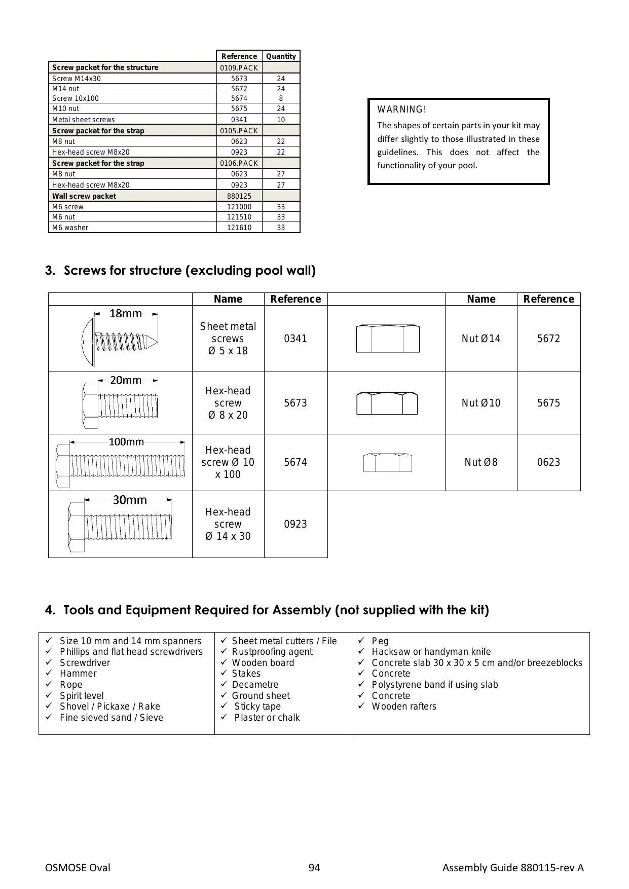
| Reference | Quantity | |
| Screw packet for the structure | 0109.PACK | |
| Screw M14x30 | 5673 | 24 |
| M14 nut | 5672 | 24 |
| Screw 10x100 | 5674 | 8 |
| M10 nut | 5675 | 24 |
| Metal sheet screws | 0341 | 10 |
| Screw packet for the strap | 0105.PACK | |
| M8 nut | 0623 | 22 |
| Hex-head screw M8x20 | 0923 | 22 |
| Screw packet for the strap | 0106.PACK | |
| M8 nut | 0623 | 27 |
| Hex-head screw M8x20 | 0923 | 27 |
| Wall screw packet | 880125 | |
| M6 screw | 121000 | 33 |
| M6 nut | 121510 | 33 |
| M6 washer | 121610 | 33 |
WARNING!
The shapes of certain parts in your kit may differ slightly to those illustrated in these guidelines. This does not affect the functionality of your pool.
3. Screws for structure (excluding pool wall)
| Name | Reference | Name | Reference | ||
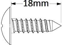 | Sheet metal screws∅ 5 x 18 | 0341 | 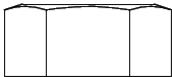 | Nut ∅14 | 5672 |
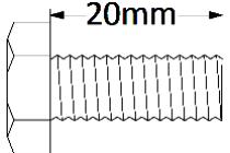 | Hex-head screw∅ 8 x 20 | 5673 | 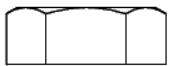 | Nut ∅10 | 5675 |
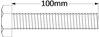 | Hex-head screw ∅ 10 x 100 | 5674 | 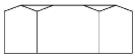 | Nut ∅8 | 0623 |
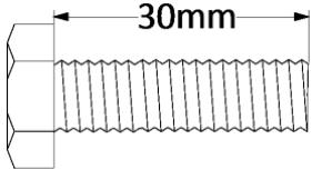 | Hex-head screw∅ 14 x 30 | 0923 | |||
4. Tools and Equipment Required for Assembly (not supplied with the kit)
| ✓ Size 10 mm and 14 mm spanners✓ Phillips and flat head screwdrivers✓ Screwdriver✓ Hammer✓ Rope✓ Spirit level✓ Shovel / Pickaxe / Rake✓ Fine sieved sand / Sieve | ✓ Sheet metal cutters / File✓ Rustproofing agent✓ Wooden board✓ Stakes✓ Decametre✓ Ground sheet✓ Sticky tape✓ Plaster or chalk | ✓ Peg✓ Hacksaw or handyman knife✓ Concrete slab 30 x 30 x 5 cm and/or breezeblocks✓ Concrete✓ Polystyrene band if using slab✓ Concrete✓ Wooden rafters |
5. Preparing the site
5.1. Choice of terrain
IMPORTANT: The site must be perfectly flat, hard, and level. The level difference must not exceed 2 cm from one end of the pool to the other.
Your pool is intended to be placed on the ground only.
■ Earthmoving must always be performed on firm ground and not on backfill.
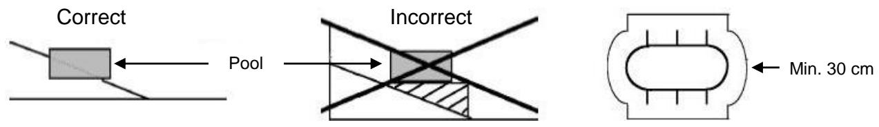
■ If the site is sloped, the earth must always be removed from the higher section and not to the lower section.
■ When the site is level, you must remove stones, grass, roots, and compact the earth firmly. If this operation is not correctly performed, grass and roots may grow under the liner and damage it. A thin layer of very fine sieved sand (1 to 1.5 cm thick) should be spread in order to level the entire surface.
■ If you install your pool on a slab or concrete ground, make sure the level is correct and the cement is not coarse. Recommended concrete proportions: 150 kg of cement per m³ of sand mixed with a concrete mixer. The slab dimensions must exceed the pool dimensions by at least 30 cm all around the pool.
■ Do not forget to dig the trenches necessary for embedding the horizontal supports (see chapter 7: "Trenching").
■ In any case, you must place your pool on a floor mat to protect the liner.
■ The warranty will only be applicable if the liner has been correctly protected.
■ Remember that your pool will be very heavy when filled with water. (Example: a 7.30 m oval swimming pool = 29 tons of water).
■ Provide sufficient space around the pool to move and play freely.
- Determine the filter's location based on the electric power available and preferably opposite the prevailing winds.
text_image
Correct Pool Incorrect Min. 30 cm5.2. Overall dimensions for oval pools
The measurements indicated give the approximate pool wall dimensions and do not include the surrounding area space required (dimensions +/-3%).
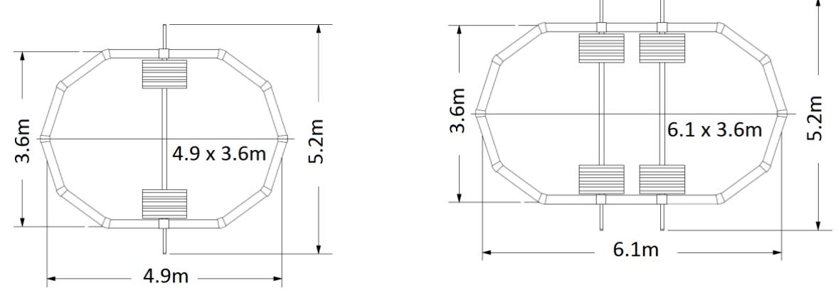
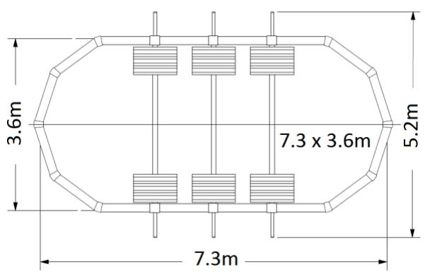
text_image
3.6m 7.3 x 3.6m 5.2m 7.3m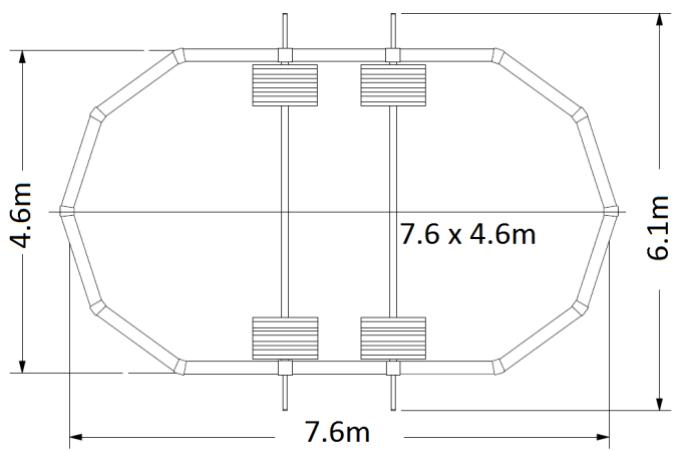
text_image
4.6m 7.6 x 4.6m 6.1m 7.6m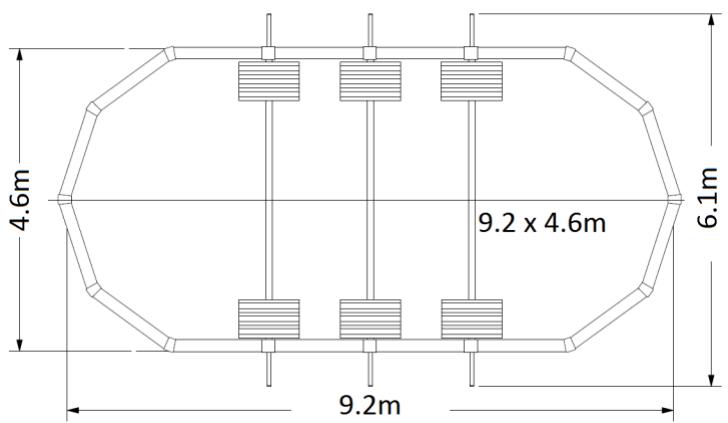
text_image
4.6m 9.2 x 4.6m 6.1m 9.2m5.3. Oval pool outline
All the measurements of the wall dimensions are expressed in metres (+/-3%).
Prepare the following:
- stakes for indicating your pool’s limits,
- a stake connected to a 6-metre rope for tracing your pool's outline,
- sand, plaster, or chalk to trace your pool's outline.
Trace your pool's outline using the diagram corresponding to your pool's dimensions. The dimensions provided for the distance between each strut correspond to measurements between centrelines. They must be respected as far as possible.
text_image
4,85 R1,81 R1,81 3,61 1 1 1,24
text_image
6,08 R1,81 R1,81 3,61 1 1,24 1 2,47
other
| Dimension | Value | | --------- | ----- | | Total Length | 7,32 | | R1.81 (Right) | 7,32 | | R1.81 (Left) | 7,32 | | R1.61 (Right) | 7,32 | | R1.61 (Left) | 7,32 | | 0.62 (Bottom) | 0.62 | | 1.24 (Bottom) | 1.24 | | 1.24 (Top) | 1.24 | | 0.62 (Bottom) | 0.62 | | 3.71 (Bottom) | 3.71 | The label '3,61' appears in the left side of the diagram.
other
| Dimension | Value | | --------- | ----- | | Top Width | 7,64 | | Bottom Width | 4,57 | | Left Side Height | R2,29 | | Middle Width | 0,77 | | Right Side Height | R2,29 | | Bottom Width (Right) | 3,07 | | Middle Width (Left) | 1,53 | | Bottom Width (Left) | 0,77 |
other
| Dimension | Value | | --------- | ----- | | Total Length | 9,17 | | Height | 4,57 | | Width | 0,77 | | Top Margin Ratio | R2,29 | | Bottom Margin Ratio | 4,63 | | Top Margin Ratio | 1,53 | | Bottom Margin Ratio | 1,53 | | Top Margin Ratio | 0,77 | | Bottom Margin Ratio | 4,63 |6. Assembling the support legs
Assemble a full “support legs – vertical posts - straps – pressure plates” set in order to be sure of the positioning of your trenches.
text_image
5712 5617 5673 5672 M14 nut 5726 5675 M10 nut 5674 M 14 x 30 5672 M14 nut 5675 M10 nut 5726 5674 M 14 x 30 3177 Top plate 0341 2 3234 Guide rail 0923 M8 x 20 0623 M8 nut7. Trenching
Depending on the dimensions of your pool, several trenches must be planned for the installation of the horizontal rails. You will also need to leave grooves for wedging the ends of the trenches.
The trenches must correspond exactly to the dimensions provided. Check that the trenches are parallel by digging the central trench first.
7.1. Without concrete slab
Plan for wedging the support legs, rails and ends of the trenches with breezeblocks or cement plates (for example: 30 x 30 x 5 cm on two layers).
text_image
(cm on two layers). Pool interior Pool exterior 137 cm 48 cm Depth 13.8 cm Sand Breezeblocks or cement plates| Pool dimensions | S |
| 5.15 x 3.90 m | 1.24 m |
| 6.35 x 3.90 m | 1.24 m |
| 7.60 x 3.90 m | 1.24 m |
| 7.90 x 4.85 m | 1.54 m |
| 9.40 x 4.85 m | 1.54 m |
other
| Dimension | Value | | --------------- | ------- | | Height (x) | 5.15 x 3.90 m | | Height (y) | 6.35 x 3.90 m | | Height (z) | 7.60 x 3.90 m | | Height (w) | 7.90 x 4.85 m | | Height (x,y) | 9.40 x 4.85 m | | Width (x) | 1.24 m | | Width (y) | 1.24 m | | Width (z) | 1.24 m | | Total Width (x, y) | 1.54 m | | Total Width (y, z) | 1.54 m | | Total Height (x, y) | 30cm | | Total Height (y, z) | 48cm | | Total Height (w, x) | 137cm | | Total Height (w, y) | 15cm | | Total Height (w, z) | 30cm | | Total Height (w, w) | 89cm |7.2. On a concrete slab
Type: 10 cm thick reinforced concrete slab
Recommended concrete proportions: 150 kg of cement per m ^3 of sand mixed with a concrete mixer.
Leave pockets using polystyrene strips or wooden rafters in a rectangular area 15 cm wide x 14 cm high for the horizontal rails and end wedging.
The slab dimensions must exceed the pool dimensions by at least 30 cm all around the pool.
8. Assembling the straps
Ensure that the ground has been correctly levelled before installing the straps. It is imperative that they lie flat on the ground. If the pool is installed on a concrete slab, leave pockets for the strap fastening bolts. 18 mm diameter holes are sufficient.
IMPORTANT: use the screws on top and the nuts on the bottom to assemble. A screw is provided for each hole.
The assembly process includes one strap at the end and another one in the middle of each post.
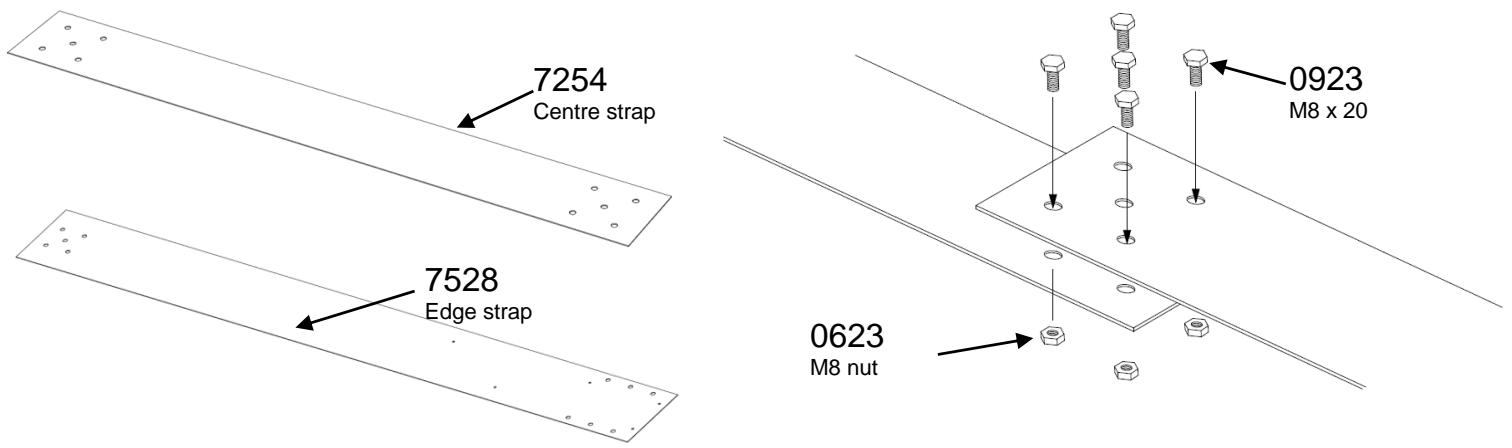
text_image
7254 Centre strap 7528 Edge strap 0923 M8 x 20 0623 M8 nut9. Assembling the structure
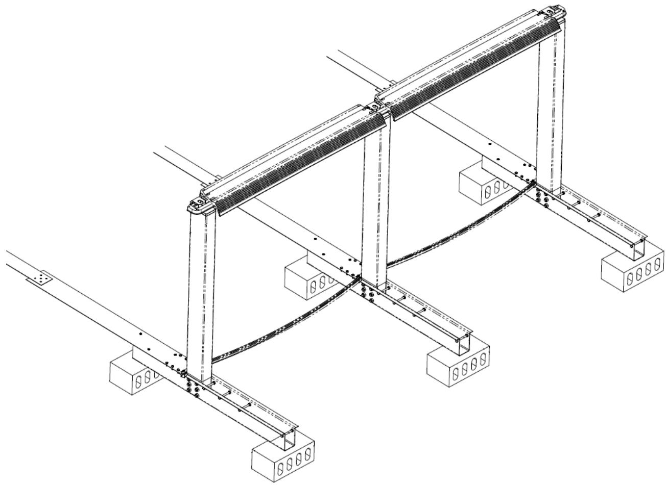
To ensure the correct spacing and alignment, fasten the top plates on to the support legs, install the ledge pieces without fastening them and slide in the bottom rails. Then proceed with assembling the pressure plates before covering them with sand:
natural_image
Technical line drawing of a structural frame assembly with supports and mounting blocks (no text or symbols)Very carefully check the spacing between all the posts (side S in chapter 7.1) and that they are positioned vertically. The levels between each of them must also be checked.
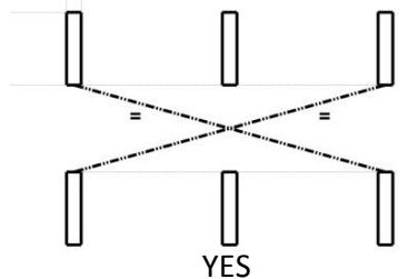
After alignment completion, ensure that the diagonals are equal. Once the wedging is completed, fill the trenches with a bit of sand.
text_image
+ = + YES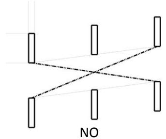
natural_image
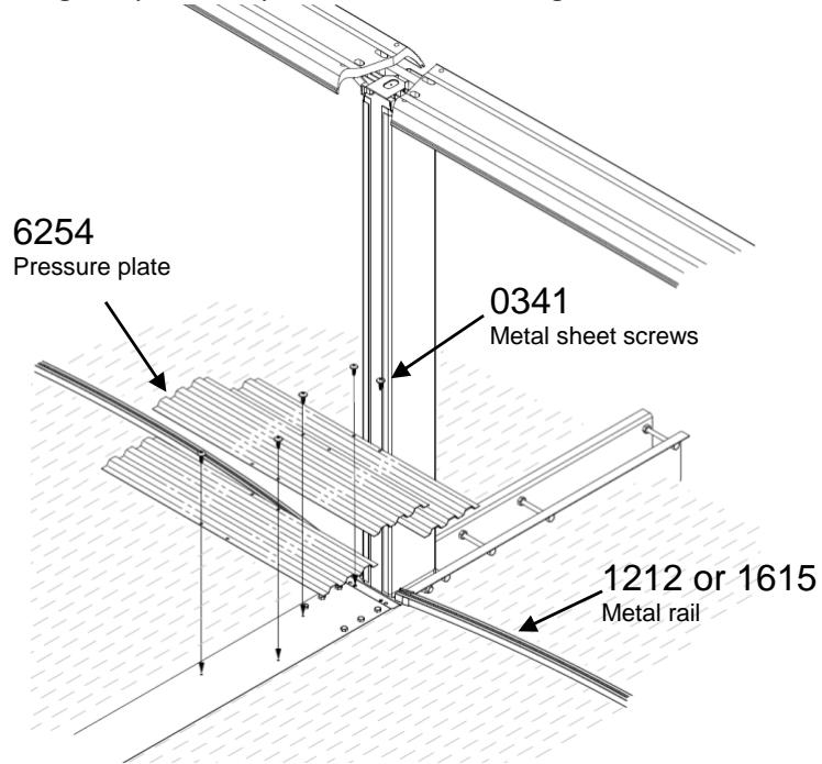
Pure diagram of intersecting vertical bars with dashed lines, no text or symbols presentThen proceed with assembling the pressure plates before covering them with sand:
text_image
6254 Pressure plate 0341 Metal sheet screws 1212 or 1615 Metal rail10. Assembling the bottom rails
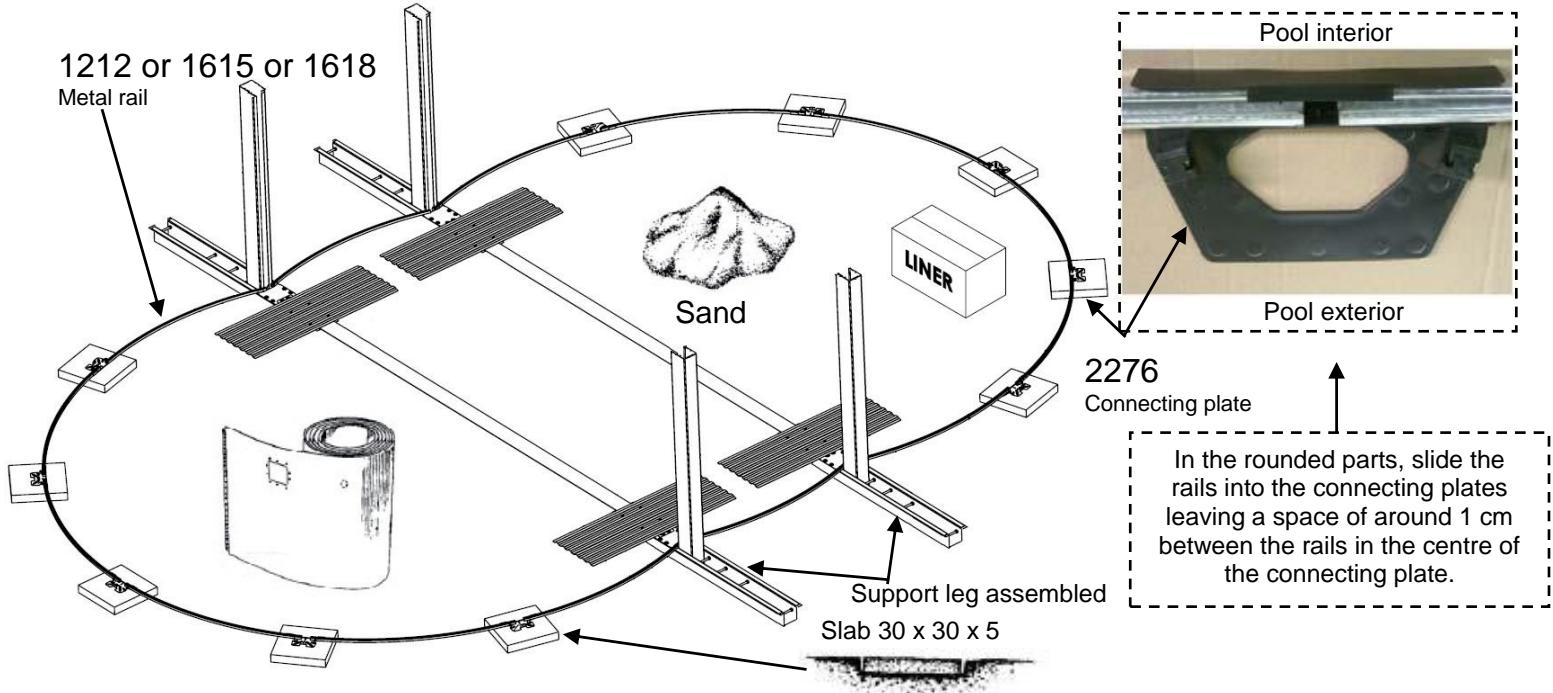
If the pool is not installed on a concrete slab, place a concrete slab of around 30 × 30 × 5 cm at each connecting point of the bottom rails (rounded parts of the pool). These slabs must be placed in such a way that their surface arrives exactly at ground level.
WARNING: The connecting plate must lie totally flat against the entire length of the concrete slab. The absence of a concrete slab or using one that is too short may result in an inadequate installation and could lead to the collapse of the pool.
Before assembling the bottom rails of the rounded parts of the pool, place the metal sheet wall inside the enclosure of the pool.
text_image
1212 or 1615 or 1618 Metal rail Sand LINER Pool interior Pool exterior 2276 Connecting plate Support leg assembled Slab 30 x 30 x 5 In the rounded parts, slide the rails into the connecting plates leaving a space of around 1 cm between the rails in the centre of the connecting plate.11. Assembling the plastic profiles on the posts
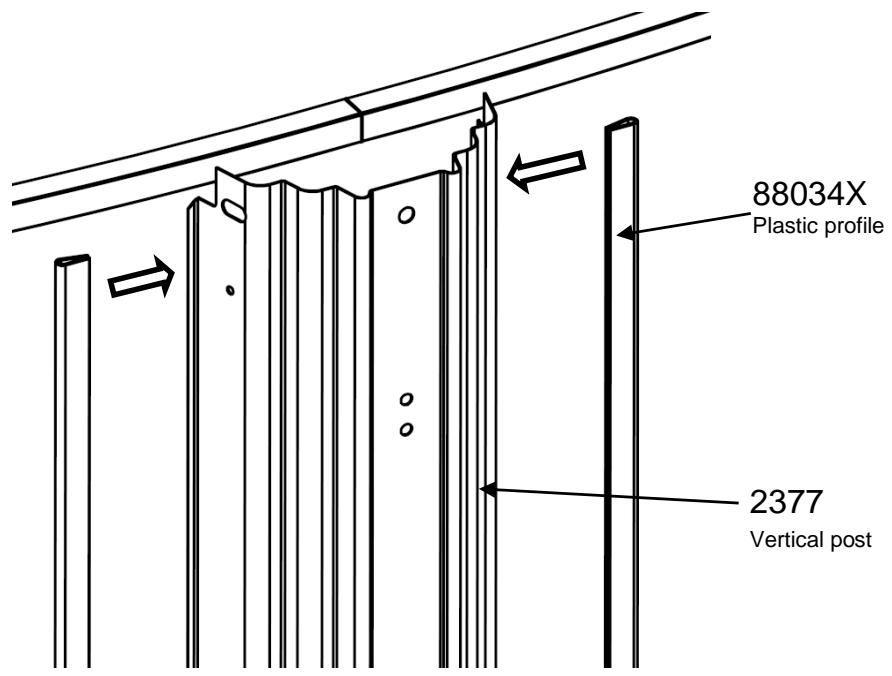
Before starting to assemble the posts themselves, assemble the plastic profiles on to the posts (note there are 2 types of posts: for the round part and the straight part).
text_image
88034X Plastic profile 2377 Vertical post12. Installation of the pool wall
WARNING: An incorrectly installed metal sheet could cause the pool to collapse. Do not install the metal sheet in windy weather.
NOTE: For some larger sized pool models, the wall is composed of two half-walls in order to facilitate handling (for some models, the weight of the wall may exceed 100 kg). This does not change the way in which the wall is installed.
Use the ladder to enter and exit the pool during installation. Take the pool wall out of the box and place it on top of the box or on a board for easy unravelling.
Ensure that the skimmer cut out is placed on the top part of the metal sheet, with the opening positioned facing the prevailing wind, so that the wind blows any impurities towards the skimmer.
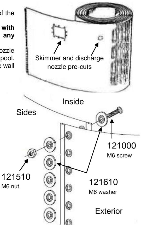
We recommend installing the metal sheet wall so that the skimmer and discharge nozzle cut outs are located on a rounded side of the pool and not on a straight side of the pool. Begin by pushing the metal sheet into the groove of the profiles and continue until the wall is completely unrolled.
Start in the middle of a connecting plate so that the bolts are hidden by a vertical post. Join the extremities of the metal sheet using the bolts and washers. The screw heads must be on the inside and the nuts on the outside. Ensure that all the bolt holes are used. It is very important for all the bolts to be adequately tightened to ensure a solid join. To protect the liner, stick a protection band (duct tape) over the screws on the inside of the pool.
IMPORTANT: Increase the stability and rigidity of the metal sheet by temporarily placing the top metal profiles and the vertical posts (round part) as you go along. On the lower part, fix the posts to their connecting plate using 2 screws; on the upper part, fix the posts to their connecting plate with 3 loosely tightened screws.
text_image
of the with any puzzle pool. e wall Skimmer and discharge nozzle pre-cuts Inside Sides 121510 M6 nut 121000 M6 screw 121610 M6 washer Exterior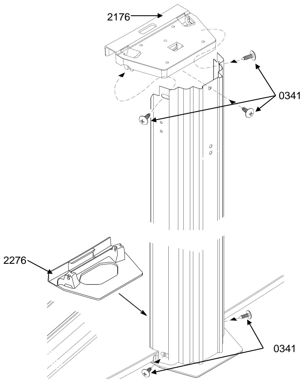
text_image
2176 0341 2276 0341INSTALL THE GROUND SHEET OR GEOTEXTILE FILM (note: the ground sheet is not included in all kits)
It is important to backfill 8 to 10 cm (mound of fine sand) all around the base of the inside of the pool and, particularly, along the sides of the pool, and to cover the entire surface of the pool with a 5 cm layer of sand. The sand prevents the liner from sliding under the metal sheet and protects it from the protruding parts of the pool structure that could perforate it (the pressure plates and strap bolts must be totally covered).
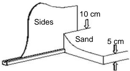
text_image
Sides 10 cm Sand 5 cmCover the prepared ground with a geotextile film that goes 10 to 12 cm up the wall. Stick the film to the wall in various places using double-sided adhesive tape. The geotextile film prevents algae from spreading under the liner
POOL WALL CUT OUTS
After assembling the pool wall, make the skimmer and discharge nozzle cut outs using metal cutters or sharp pliers. File the edges of the cut outs and apply rustproofing agent. We advise wearing gloves during this process.
NOTE: For kits containing two half-walls, perform the cut outs on just one of the half-walls and stick a protective strip (duct tape) on the unused cut outs on the inside of the pool in order to protect the liner.
13. Installing the liner (to be installed barefoot)
WARNING: This is a delicate process and must be carried out with utmost caution.
We recommended installing the liner when the outdoor temperature is between 18^ C and 25^ C. Use the ladder to enter and exit the pool during installation. Unfold the liner inside the pool and spread it out until it reaches the edges of the pool. The side where the seams are smooth is the inside of the liner.
After removing 2 or 3 of the upper rails on the rounded sides, start to pull the edges of the liner above the wall allowing it to overhang by 10 to 20 cm. Hold it in place temporarily with clothes pegs or using the rails provided for this purpose. Do not overstretch the liner. Use your feet to spread the bottom of the liner out until it reaches the base of the metal sheet wall. Repeat this on the opposite side and in two other areas. This will enable you to check that the liner is properly centred. There should not be any large folds running across it. Continue to lift the liner all around the pool, holding it in place with other clothes pegs.
Important!
The liner must be lying against the bottom of the pool before water is added.
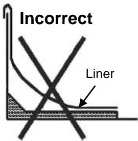
text_image
Incorrect Liner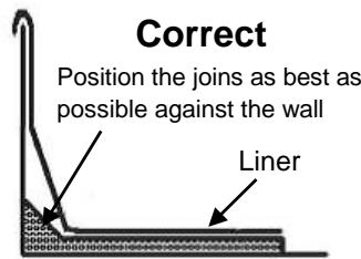
text_image
Correct Position the joins as best as possible against the wall Liner14. Filling the pool
WARNING: Do not use recovered water (from a well or river, for example).
Start filling the pool with 1 or 2 cm of water. Spread the liner out on the bottom and remove any wrinkles by sliding them with the flat of your hand from the centre of the pool towards the edge, until they are completely gone.
Once the liner is in place, you can then install the plastic and metal profiles as well as the connecting plates. Cut off the excess of the last plastic profile. Install the top rails perpendicular to the bottom rails and place the connecting plates back on the rails without fixing them.
You must stay in or nearby the pool until the water level reaches a height of 20 cm. From within the pool, gently tap the base to position the pool wall on the ground tracks. At this stage, if the liner is laid correctly, you can permanently fix the connecting plates with the fastening screws.
Ensure that the cut outs in the liner for the skimmer and discharge nozzle have been done before totally filling the pool with water (see chapter 16: "FILTRATION").
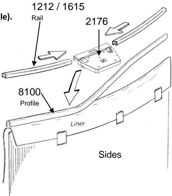
text_image
1212 / 1615 Rail 2176 8100 Profile Liner Sides15. Installation of the ledge pieces and covering plates
The ledge pieces must be assembled in a certain position. The widest edge must be on the outside.
The ledge pieces must be positioned between the posts.
Each ledge piece extremity must be screwed onto a top plate or connecting plate. You may need to gently move the posts to the left or right to install the ledge pieces. Do not fully tighten the screws until they are all in place.
Fit the covering plates over the extremities of the ledge pieces and centre them. The narrowest part of the covering plate should be located on the inside of the pool.
WARNING: The covering plates for the round and straight parts of the pool are different.
Round part
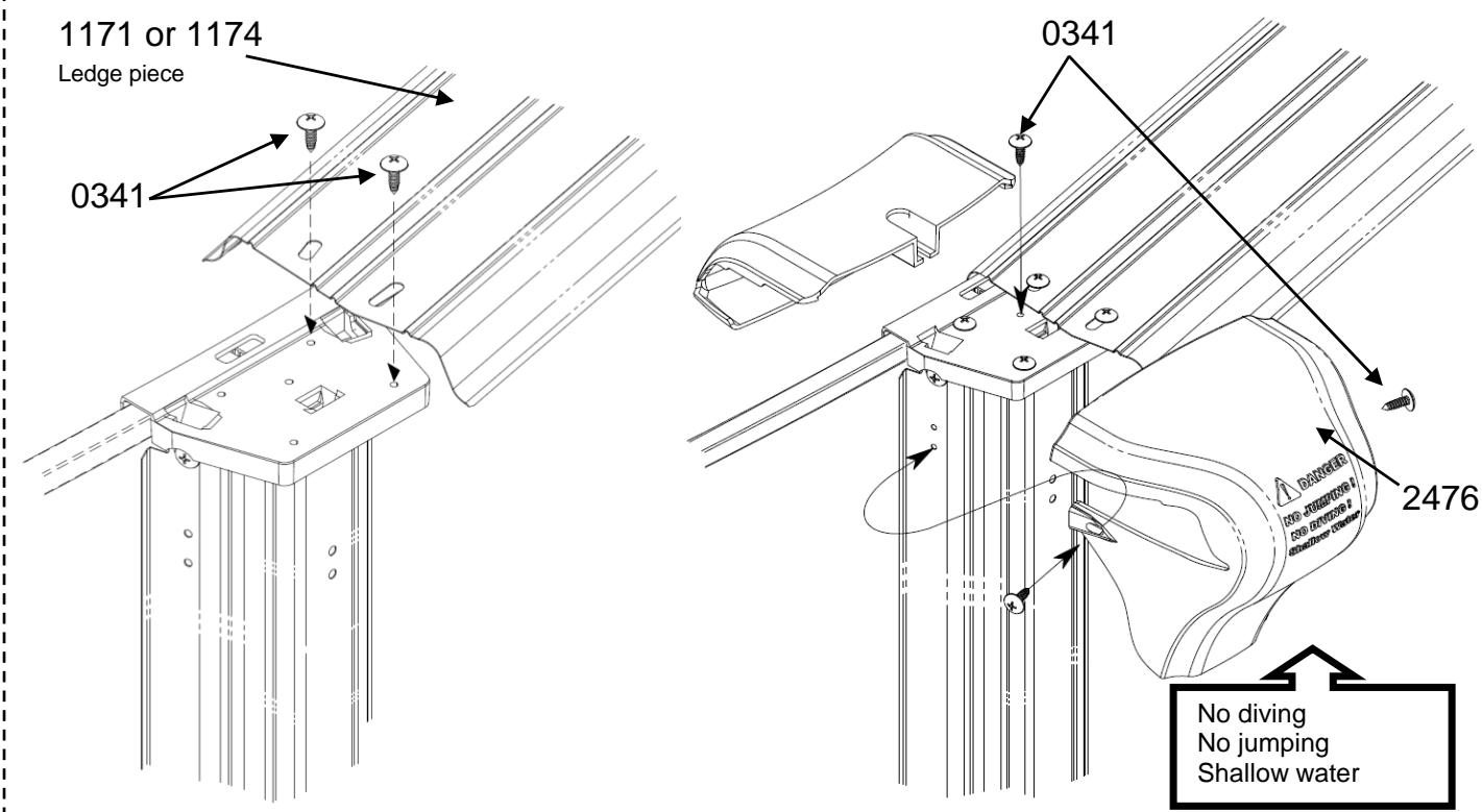
text_image
1171 or 1174 Ledge piece 0341 0341 2476 No diving No jumping Shallow water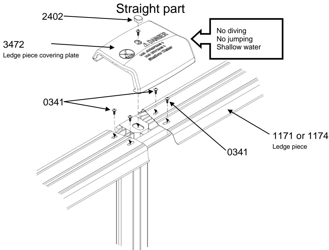
text_image
Straight part 2402 3472 Ledge piece covering plate No diving No jumping Shallow water 0341 0341 1171 or 1174 Ledge piece16. Filtration
IMPORTANT: All filtration systems comply with installation standard NF C 15-100 stipulating that all electrical devices located within 3.50 m of the pool and freely accessible must be powered by very low voltage (12 V).
Any device powered with 220 V must be located at least 3.50 m from the edge of the pool. This means that:
■ This means that for a filter, the device must be installed more than 3.50 m from the pool,
■ For filtering skimmers (depending on the kit), the transformer must be located more than 3.50 m from the pool.
NOTE: All threaded connectors should be attached with Teflon tape, wound in the opposite direction of the thread.
Seek advice from the manufacturer for any modifications to one or more filtration system elements.
Depending on the filter media used, refer to the quantities listed opposite to be put in the tank.
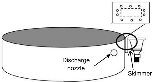
text_image
Discharge nozzle Skimmer| Filtration size | Sand | Aqualoon ball |
| Filtration 4 m^3/h | 20 kg | 560 g |
| Filtration 6 m^3/h | 35 kg | 980 g |
| Filtration 8 m^3/h | 75 kg | 2100 g |
| Filtration 10 m^3/h | 75 kg | 2100 g |
| Filtration 12 m^3/h | 75 kg | 2100 g |
TO ASSEMBLE THE FILTER SYSTEM, REFER TO THE USER GUIDE IN THE FILTRATION BOX
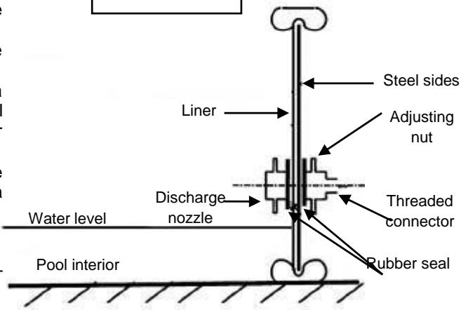
16.1. Installing the discharge nozzle
When assembling pools with a filtration system operating through the pool wall, the following procedures must be carried out:
- When the pool's water level reaches 5 or 6 cm from the discharge nozzle, install the nozzle as follows (see figure 1).
- Cut out the part of the liner covering the discharge nozzle using a metal cutter (see figure 2) and pull the cut out liner back onto the pool wall. You may find it helpful to place a piece of flat wood on the other side of the liner to the cut out to keep it down.
■ From the inside of the pool, install the rubber joint and the discharge nozzle (see figure 3) and screw in from the outside of the pool with a clamping nut.
■ Screw the connector or stopper valve (depending on the model).
■ Install the ringed hose and the hose clamp.
■ Connect the corrugated pipe to the valve (return to pool) from the filter (threaded connector with Teflon tape and ring clamp).
Figure 1
text_image
Steel sides Liner Adjusting nut Discharge nozzle Threaded connector Rubber seal Water level Pool interior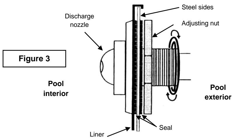
text_image
Figure 3 Pool interior Discharge nozzle Steel sides Adjusting nut Pool exterior Liner Seal
Figure 2
16.2. Installing the skimmer
When the water level in the pool reaches 5 to 6 cm below the skimmer, install it using the type of joint included with your skimmer (single or double). (Figure 4):
■ By pressing on the liner (using, for example, a pen cap), find the pre-drilled holes in the plate.
■ Stamp the holes using a Philips-head screwdriver.
■ Position the rubber joints according to figure 4.
■ Place the flange (or frame) on the rubber joint.
■ Screw the flange onto the metal sheet.
■ Screw the threaded connector or stopper valve (depending on the model) with Teflon tape, the pipe and the ring clamp on to the skimmer.
- Cut out the part of the liner obstructing the skimmer from inside the pool.
■ Connect the corrugated pipe from the skimmer to the filter pump.
■ Let the water level rise up to the middle of the skimmer.
■ Check the seal and tighten the screws if necessary.
■ Permanent water-resistance will only be obtained after tightening all the screws progressively and regularly.
For permanent water-resistance, retighten all the screws over the course of the next few days.
WARNING: Do not tighten the screws of the skimmer and discharge nozzle until the water level is a few centimetres from the parts to be installed. The water pressure should stretch the liner out nicely.
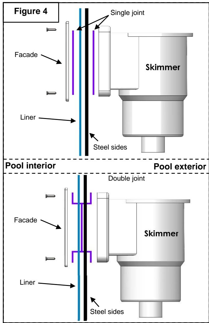
text_image
Figure 4 Single joint Skimmer Facade Liner Steel sides Pool interior Pool exterior Double joint Skimmer Facade Liner Steel sides17. Maintenance and Use Guidelines
Non-compliance with maintenance instructions may cause serious health risks, particularly for children.
FILTRATION
In order to eliminate suspended solids, you must have a good filtration system. During the season when you are using your pool, the filtration system must be operated each day, long enough to ensure the water volume is renewed at least every 24 hours (the minimum filtration duration depends on use and water temperature). We recommend splitting the filtration into 2 periods (once in the morning and once at night).
| Inner wall dimensions => | 4.85 x 3.60 m | 6.10 x 3.60 m | 7.30 x 3.60 m | 7.6 x 4.6 m | 9.20 x 4.60 m | |||
| Water volume | 19 m^3 | 24 m^3 | 29 m^3 | 37 m^3 | 45 m^3 | |||
| Filtering capacity | 4 m^3/h | 6 m^3/h | 4 m^3/h | 6 m^3/h | 6 m^3/h | 8 m^3/h | 8 m^3/h | 10 m^3/h |
| Daily filtration duration | 4 hrs 45 | 3 hrs 15 | 6 hrs | 4 hrs | 4 hrs 50 | 3 hrs 30 | 4 hrs 30 | 3 hrs 45 |
You must:
■ Ensure that suction ports are free of obstructions.
■ Stop the filtration system during maintenance operations.
■ Periodically check the filter's clogging level.
■ Please consult the filter instructions for filtration system maintenance and use.
■ Check the fill level.
■ Replace any element or set of elements that become deteriorated. Only use parts that have been approved by the manufacturer.
ACCESSORIES
The following accessories are required for proper pool maintenance: surface accessories (example: net), bottom accessories, monitoring and repair accessories (example: repair kit).
Before using a robotic cleaner, clean the filter media of your filter system. Refer to the instructions provided with your filter system. Also check the filtration power necessary for the correct functioning of your equipment.
CHEMICAL TREATMENT
3 operations are required for treating the water:
- Adjusting the water's pH level using a test kit and pH corrector. The pH (potential hydrogen) indicates whether and to which extent the water is acidic or alkaline. The ideal for pool water is to be as close as possible to the pH of lacrimal fluid, i.e. 7.4.
■ Combating algae using an anti-algae product.
■ Disinfecting the water using chlorinated products in order to destroy any microorganisms.
These treatment and monitoring operations should be performed at least once a week to ensure proper water quality.
Water treatment chemicals must be stored in a dry, ventilated area and out of reach of children.
WARNING:
Never put chlorine or other agents directly in the pool, as this could damage the liner.
TIPS:
■ Place a container filled with water at the foot of the ladder so people can rinse their feet before getting into the pool.
■ A thermal cover (bubble cover) will allow you to enjoy your pool to the fullest since it will heat the water, avoid heat loss at night, prevent leaves and insects from falling in the water and prevent the chlorine from evaporating.
■ No diving or walking on the ledge pieces.
FILLING AND EMPTYING
You should fill the pool so that the water level is at least in the middle of the skimmer.
You should never completely drain the pool. If absolutely necessary, draining should not be performed during high winds and should be performed as quickly as possible. Do not leave the pool empty for more than 24 hours as the liner may shrink.
Specific Cases and Handling
Your pool is equipped with a filtration system that removes physical impurities such as insects, hair, leaves, and so on. The chemical treatment of the water, which complements the physical treatment, is necessary for keeping the water fit for bathing. During normal use, weekly cleaning of your pool is sufficient. However, you may encounter unusual problems that may be resolved by following the recommendations in the table below.
| TREATING THE WATER: problems and solutions | ||
| Issues | Causes | Solutions |
| Cloudy Water | Hard water and presence of suspended particles | Adjust the pHPlace a flocculating agent in the skimmer or directly in the poolWash the filter (BACKWASH position until the water evacuated to the drains is clean enough for a sand filter system). |
| Chlorine odourEye and nose irritation | pH too highChloramine content too high | Adjust the pH.Shock with chlorine.Wash the filter. |
| Green waterSlippery floors and wallsBrown water | Green water: algae formation or proliferation.Brown water: presence of organic matter. | Brush the walls and skimmer basket.Adjust the pH.Shock-treat the system using a suitable cleaning agent and clean the filter (see the filter guidelines) |
| Rough walls | Hard water | Remove the deposits with a brush or a robotic cleaner.Clean the pool and descale the filter with suitable agents.Adjust the pH.Add a water hardness regulating agent. |
| Black waterline | Presence of greasy deposits on the waterline. | Clean the waterline with a suitable agent.Add a flocculating agent. |
18. Dismantling the pool
We strongly advise against dismantling your pool. If, however, you are obliged to dismantle your pool, repeat the assembly process in reverse.
WARNING: Do not lift the liner when it is still filled with water.
To dismantle the pool, we recommend you take the following precautions:
■ Empty the pool by siphoning off the water with a pipe, or by using the filter pump.
■ Wash all the elements with soapy water.
Do not use products containing caustic soda to wash the liner.
■ Hose down all the elements with clean water and dry (to avoid perforating the liner, only clean inside the pool structure; dry out of sunlight, as soon as possible. Do not allow prolonged exposure to the air).
■ In the event of an incident (perforated liner), it may be easily fixed, even in water, using a special liner repair glue.
■ Once fully dry, wrap the liner (no talcum powder) in an opaque plastic bag and store it in a closed box. Store the liner in a dry area, protected from frost and vermin, and avoid contact with heat.
■ Roll up the metal sheet wall without bending it and tie it in position with a cord.
19. Safety Guidelines
Your children's safety depends on you!
The risk is greatest with children under the age of 5. Accidents don't just happen to others! Be prepared for them! Never leave a child alone near water of any kind. Never let your child out of your sight. Prohibit pool access if the filtration system(s) is damaged.
Reminder of a few basic safety rules, monitor and be ready to act:
■ Children should be monitored closely at all times.
■ Designate a single person responsible for safety.
- Keep children under stricter supervision when there are multiple users in the pool.
■ Never leave a child alone near a swimming pool.
■ Never leave a child who cannot swim without adult supervision.
■ Never let a child swim alone.
■ Ask people who are not strong swimmers to use personal flotation equipment.
■ Equip your child with suitable armbands or floaters when near the pool.
■ Provide life preservers and poles beside the pool.
■ Teach your children to swim as soon as possible.
■ Wet the back of your neck, arms, and legs before entering the water.
■ Never enter the water too quickly, particularly after a meal, extended sun exposure, or intensive effort.
■ Learn lifesaving techniques, particularly those specific to children.
■ Prohibit diving and jumping into the pool.
■ Prohibit running and lively games in and around the pool.
■ Do not walk or sit on the ledge pieces.
■ Do not climb along the wall.
■ The ladder must be placed on a solid base and always be level.
■ You must always face the ladder when entering or exiting the pool.
■ The ladder must be removed when not swimming.
■ Do not leave toys near the pool and in the pool when it is not supervised.
■ Never modify parts; never remove parts; and never drill holes in the pool.
- Keep the water clear and clean at all times.
■ Never operate the filtration system while using your pool.
■ Store chemical agents out of the reach of children.
■ Make sure you have a telephone near the pool so you do not need to leave your children unattended when you make a call.
■ Prohibit pool access if the filtration system is damaged.
■ Never use the ladder for other purposes than that for which it was intended, i.e. entering and exiting the pool. It is not intended for diving or jumping.
■ Periodically check that all pool parts are in good condition (e.g.: traces of rust on bolts and screws). Tighten or changes screws and nuts as necessary.
■ Follow the installation instructions carefully, and consult the safety instructions for use and storage on chemical agent packaging.
■ Memorise emergency numbers and display them near the pool (fire brigade: or ambulance: 999 or 112, poison control centre, etc.).
We recommend you secure access to the finished pool using a protective device. The equipment listed below may contribute to safety. Under no circumstances does it replace close surveillance.
■ Protective barrier (as per NF P306) with a constantly closed gate (a hedge, for example, may not be considered a barrier).
■ Cover (as per NF P 308) or manual or automatic protective shelter (as per NF P 309) correctly installed and secured.
■ Electronic presence or fall detector (as per NF P 307), operating and operational.
In case of accident:
■ Help the child out of the water as quickly as possible.
■ Immediately call the emergency services and follow the instructions provided.
■ Replace wet clothing with warm blankets.
20. Winterising Guidelines
■ Do not empty your pool.
■ Remove floating debris (leaves, small branches, insects, etc.) using the net.
■ Clean the bottom of the pool using a vacuum brush (or venturi).
■ Check the pH using a test kit and adjust as necessary.
- Use a winterising agent proportionally to the pool's water volume (see explanatory note on the product label).
■ Run the filter for about 4 hours.
■ Lower the water level to below the skimmer opening.
■ Thoroughly drain the filtration unit (pump and tank) and store it above freezing temperatures.
■ Cap the discharge nozzle and disconnect the hoses (not included in the kit).
■ Installing winter air pillows (not included)
■ Cover the pool with a winter cover.
REMARKS: If you do not cover your pool and the water freezes, never break the ice. When it is cold, you can place a floating object in your pool in order to minimise the pressure caused by ice formation.
21. Warranty
The structure and accessories of our swimming pools have a 2-year warranty against all manufacturing defects, in the framework of normal use of the pool. It does not cover the wear and tear of parts.
This warranty is limited to exchanging defective parts with your reseller.
Liners are warranted for two years solely for seam defects (peeling). The warranty shall not cover holes due to improper handling during assembly or using unsuitable treatment agents. Porosity issues and fading are caused by misuse or unsuitable treatment agents. The filters are under warranty for two years under normal use and in compliance with the assembly instructions except for seals and wear parts.
Products cannot be modified. Only TRIGANO JARDIN replacement parts should be used. For any Customer Service enquiries please visit the following website: http://sav.triganojardin.com
IMPORTANT! For the warranty to be valid, you must keep proof of purchase including the reseller's stamp as well as the purchase date and the quality control sheet. You must change all damaged items or set of items as soon as possible. Only use TRIGANO JARDIN approved parts.
We thank you and congratulate you for having acquired a pool from TRIGANO PISCINES.
This pool will guarantee you exceptional quality and reliability and we hope it will meet your expectations.