
SCC-C6435P - Surveillance Camera SAMSUNG - Free user manual and instructions
Find the device manual for free SCC-C6435P SAMSUNG in PDF.
| Product Type | Single-body SmartDome WDR Camera with Lens |
| Brand | SAMSUNG |
| Model | SCC-C6435P |
| Power Supply | AC 24V ± 10% (50Hz ± 0.3Hz) |
| Power Consumption | 20W |
| Broadcasting System | PAL |
| Image Sensor | CCD ExView HAD PS 1/4 inch |
| Effective Pixels | 752(H) x 582(V) |
| Horizontal Resolution | 540 TV lines (color) / 570 TV lines (B/W) |
| Signal-to-Noise Ratio | Approx. 50dB |
| Lens | 32x optical zoom, focal length 3.55~113 mm, aperture F1.69 (Wide) ~ F4.17 (Tele) |
| Digital Zoom | Up to 16x (total 512x) |
| WDR (Wide Dynamic Range) | Yes, x160 |
| Day/Night Function | Automatic, with IR filter |
| Pan Range | 360° endless |
| Pan Speed | Preset: 400°/s max; Manual: 0.1° ~ 180°/s (64 steps) |
| Tilt Range | 0° ~ 180° |
| Tilt Speed | Preset: 200°/s max; Manual: 0.1° ~ 90°/s (64 steps) |
| Alarm Inputs/Outputs | 8 inputs, 3 outputs (1 dry contact relay) |
| Operating Temperature | -10°C to +50°C |
| Operating Humidity | Up to 90% |
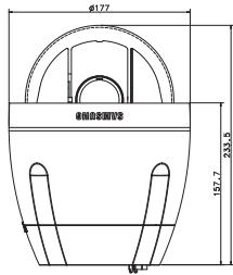
| Dimensions (Dome) | Diameter 147.65 mm; Dimensions: 177 mm (ø) x 194.3 mm (H) |
| Net Weight | 2,544 g |
| Maintenance and Cleaning | Clean with a soft, dry cloth; do not use abrasives or liquid products |
| Safety Instructions | Do not open the housing; use only the specified adapter; avoid moisture and shock |
Frequently Asked Questions - SCC-C6435P SAMSUNG
User questions about SCC-C6435P SAMSUNG
0 question about this device. Answer the ones you know or ask your own.
Ask a new question about this device
Download the instructions for your Surveillance Camera in PDF format for free! Find your manual SCC-C6435P - SAMSUNG and take your electronic device back in hand. On this page are published all the documents necessary for the use of your device. SCC-C6435P by SAMSUNG.
USER MANUAL SCC-C6435P SAMSUNG
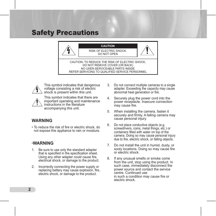
This symbol indicates that dangerous voltage consisting a risk of electric shock is present within this unit.

This symbol indicates that there are important operating and maintenance instructions in the literature accompanying this unit.
WARNING
- To reduce the risk of fire or electric shock, do not expose this appliance to rain or moisture.
·WARNING
- Be sure to use only the standard adapter that is specified in the specification sheet. Using any other adapter could cause fire, electrical shock, or damage to the product.
-
Incorrectly connecting the power supply or replacing battery may cause explosion, fire, electric shock, or damage to the product.
-
Do not connect multiple cameras to a single adapter. Exceeding the capacity may cause abnormal heat generation or fire.
- Securely plug the power cord into the power receptacle. Insecure connection may cause fire.
- When installing the camera, fasten it securely and firmly. A falling camera may cause personal injury.
- Do not place conductive objects (e.g. screwdrivers, coins, metal things, etc.) or containers filled with water on top of the camera. Doing so may cause personal injury due to fire, electric shock, or falling objects.
- Do not install the unit in humid, dusty, or sooty locations. Doing so may cause fire or electric shock.
-
If any unusual smells or smoke come from the unit, stop using the product. In such case, immediately disconnect the power source and contact the service centre. Continued use in such a condition may cause fire or electric shock.
-
If this product fails to operate normally, contact the nearest service centre. Never disassemble or modify this product in any way. (SAMSUNG is not liable for problems caused by unauthorized modifications or attempted repair.)
- When cleaning, do not spray water directly onto parts of the product. Doing so may cause fire or electric shock.
CAUTION
- Do not drop objects on the product or apply strong shock to it. Keep away from a location subject to excessive vibration or magnetic interference.
- Do not install in a location subject to high temperature (over 122^ ), low temperature (below 14^ ), or high humidity. Doing so may cause fire or electric shock.
- If you want to relocate the already installed product, be sure to turn off the power and then move or reinstall it.
- Remove the power plug from the outlet when then there is a lightning. Neglecting to do so may cause fire or damage to the product.
- Keep out of direct sunlight and heat radiation sources. It may cause fire.
-
Install it in a place with good ventilation.
-
Avoid aiming the camera directly towards extremely bright objects such as sun, as this may damage the CCD image sensor.
- Apparatus shall not be exposed to dripping or splashing and no objects filled with liquids, such as vases, shall be placed on the apparatus.
- The Mains plug is used as a disconnect device and shall stay readily operable at any time.
Important Safety Instructions
- Read these instructions.
- Keep these instructions.
- Heed all warnings.
- Follow all instructions.
- Do not use this apparatus near water.
- Clean only with dry cloth.
- Do not block any ventilation openings. Install in accordance with the manufacturer's instructions.
- Do not install near any heat sources such as radiators, heat registers, or other apparatus (including amplifiers) that produce heat.
- Do not defeat the safety purpose of the polarized or grounding-type plug. A polarized plug has two blades with one wider than the other. A grounding type plug has two blades and a third grounding prong. The wide blade or the third prong is provided for your safety. If the provided plug does not fit into your outlet, consult an electrician for replacement of the obsolete outlet.
- Protect the power cord from being walked on or pinched particularly at plugs, convenience receptacles, and the point where they exit from the apparatus.
- Only use attachments/accessories specified by the manufacturer.
-
Use only with cart, stand, tripod, bracket, or table specified by the manufacturer, or sold with the apparatus.
-
Unplug this apparatus. When a cart is used, use caution when moving the cart/apparatus combination to avoid injury from tip-over.
- Refer all servicing to qualified service personnel. Servicing is required when the apparatus has been damaged in any way, such as power-supply cord or plug is damaged, liquid has been spilled or objects have fallen into the apparatus, the apparatus has been exposed to rain or moisture, does not operate normally, or been dropped.
Contents
Overview 8
About this guide 8
Product overview 8
Main features 8
Components 8
CHECKING COMPONENTS IN THE PACKAGE. 8
NAMES OF EACH PART 9
Installation 10
Before installation 10
THINGS TO KEEP IN MIND DURING INSTALLATION AND USE.....10
Initial settings 10
CAMERA ADDRESS SETUP 10
SETTING COMMUNICATION PROTOCOL 11
BAUD RATE SETTING 12
SETTING RS-422A/RS-485 TERMINATION 13
Adapter cable connection. 15
Cable connection 16
Installation precautions 19
Separately sold products for installation 19
Installing the camera 24
Camera Setup 28
Camera set 32
CAMERA ID 32
V-SYNC 32
DAY/NIGHT 33
MOTION DET. 36
ZOOM SPEED 39
DIGITAL ZOOM 39
DISPLAY ZOOM 40
DISPLAY P/T 41
EXIT 41
Video set 42
IRIS 42
ALC 42
SHUTTER 45
AGC. 46
MOTION 47
WHITE BAL 48
FOCUS MODE 49
SPECIAL 50
EXIT 52
Preset 53
Zone set. 55
PRIVACY ZONE 55
ZONE DIR SET 56
ZONE AREA SET 57
Auto set 60
AUTO PAN 60
PATTERN 62
SCAN 63
AUTO PLAY 64
Alarm set 65
ALARM PRIORITY SET 66
ALARM IN SET 66
ALARM OUT SET 66
AUTO SET 66
AUX OUT CONTROL 66
Other set 67
PROPORTIONAL P/T 67
TURBO P/T 67
AUTO CAL 67
D-FLIP 68
CAMRESET 68
LANGUAGE 68
password 69
RS-485 70
Clock set 70
System info 71
Shortcut keys. 72
Product Specifications 75
About this guide
This user guide includes basic instructions for the product. It is recommended that all users read this guide before use.
This guide is divided as follows:
- "Overview" introduces the user guide and product related information.
"Installation" explains how to set and install the product.
"Camera Setup" presents the structure of the Setup menu for the SCC-C6435(P)/6433(P) including a detailed explanation of the functions performed in each menu. - "Product Specifications" provides the specifications of the product.
Product overview
This camera is a zoom lens built in smart dome camera which provides you with the best monitoring function in connection with CCTV at banks or companies. This camera is a high quality surveillance camera using x32 zoom lens and digital zoom IC, it can catch clear images up to 510 times.
This camera uses an Alarm function for alert situations and moving camera in the direction you want, ZOOM-IN and ZOOM-OUT functions can be remote controlled.
Note
SCC-C6433(P) does not support for WDR function.
Main features
Power:DC 12V/AC 24V
Special functions
- WDR to cover the full screen regardless of its brightness
- DAY/NIGHT to improve the sensitivity by automatic conversion into the black and white mode at night or in the environment with low illumination
- White Balance to control the brightness to the illumination
- Backlight Compensation under spotlight or utmost bright illumination
- Auto Focus to automatically adjust the focus to the subject movement
Privacy zone to hide a specific area for personal privacy
PAN/TILT for precise control at high speed
Components
CHECKING COMPONENTS IN THE PACKAGE
Please check your camera and accessories are included in the package. Those components are as shown below:

SCC-C6435(P)/C6433(P)
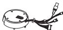
Camera Holder Adapter

User's Guide

Screws
NAMES OF EACH PART
Your camera has the following components:
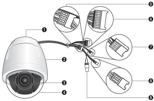
- Camera Holder Adapter
- Camera Body
- Zoom Lens
- Cover-dome
- Alarm Output: N/O, COM, N/C, AO-2, AO-1, GND
- Alarm Input (1~8): AI-8, AI-7, AI-6, AI-5, GND, AI-4, AI-3, AI-2, AI-1, GND
7.RS-485:TXD+,TXD-,RXD+,RXD - Power Input: 24V, EARTH, 24V
- Video Output
Before installation
THINGS TO KEEP IN MIND DURING INSTALLATION AND USE
- Do not disassemble the camera on your own.
- Always be careful when handling the camera. Do not strike the camera by your fists or shake it. Please be careful not to be careless when storing and operating it.
- Do not place or operate the camera in any wet environment such as rain or wet surfaces.
- Do not clean the camera with rough sandpaper. Please always use a dry cloth when cleaning it.
- Put the camera in a cool area free from direct sunlight. Otherwise, the camera may be damaged.
Initial setting
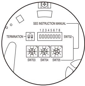
CAMERA ADDRESS SETUP
Use SW703, SW704, or SW705 for Camera Address setup. You may allocate up to 255 addresses by using SW703 to set the 3rd digit, SW704 the 2nd digit, and SW705 the 1st digit. EX) In case of Camera Address 1, see the following figure for setup.
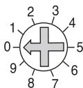
SW703
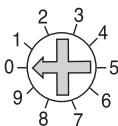
SW704
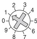
SW705
SETTING COMMUNICATION PROTOCOL
Use number 1~4 PIN of SW702 to set communication Protocol.
| PIN Comp | PIN1 | PIN2 | PIN3 | PIN4 |
| A | OFF | OFF | OFF | OFF |
| B | ON | OFF | OFF | OFF |
| C | OFF | ON | OFF | OFF |
| D | ON | ON | OFF | OFF |
| E | OFF | OFF | ON | OFF |
| F | ON | OFF | ON | OFF |
| G | OFF | ON | ON | OFF |
| H | ON | ON | ON | OFF |
| I | OFF | OFF | OFF | ON |
| J | ON | OFF | OFF | ON |
| K | OFF | ON | OFF | ON |
| L | ON | ON | OFF | ON |
| M | OFF | OFF | ON | ON |
| N | ON | OFF | ON | ON |
| O | OFF | ON | ON | ON |
| P | ON | ON | ON | ON |
A: SAMSUNG HALF
B:SAMSUNG FULL
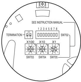
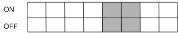
BAUD RATE SETTING
Use PIN 5 and 6 of SW702.
1 2 3 4 5 6 7 8
SW702
| BAUD RATE | PIN 5 | PIN 6 |
| 4800 BPS | ON | ON |
| 9600 BPS | OFF | ON |
| 19200 BPS | ON | OFF |
| 38400 BPS | OFF | OFF |
The factory default setting is set to 9600BPS.
SETTING RS-422A/RS-485 TERMINATION
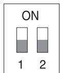
As it is shown in the structure map, when Controller and RS-422A/RS-485 is connected, it should be terminated according to the Cable feature of impedance on the each end of the transmitting line to transfer the signals in long distance by controlling the reflection of the signals to the lowest.
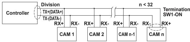
Termination: using numbers 1 and 2 PIN, turn to ON and it will be terminated.
Note
A communication error may occur if you connect multiple cameras that are assigned the same address in the network.
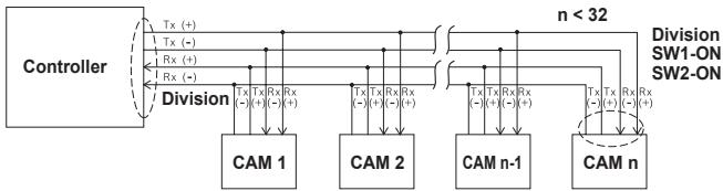
Adapter cable connection
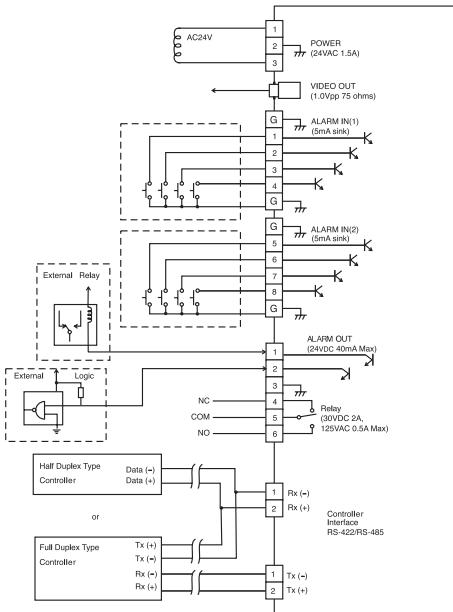
SCC-C6435 Adapter Board
Cable connection
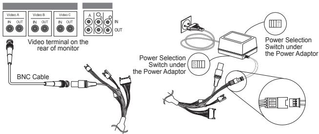
- First, connect one end of the BNC video cable connector to the Video Output Terminal (VIDEO OUT).
- Then, connect the other end of the connector to the Video Input Terminal of the monitor.
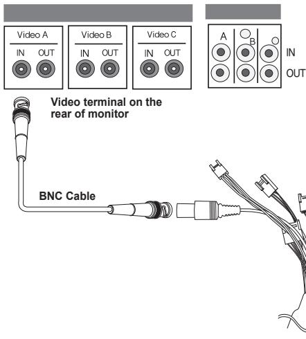
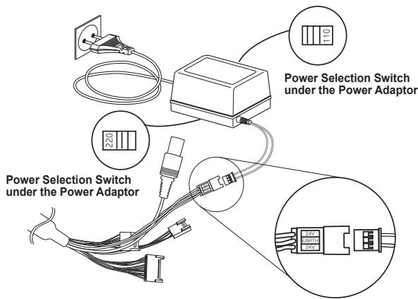
- Connect the Power Adapter to the Power Cable of the camera.
- Adjust the switch on the Power Adapter to the proper voltage. Then, connect the Power Adapter's plug to the Power Connector.
- Connect the Remote Control Terminal of the camera and the external Controller.
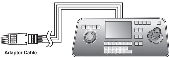
Controller
Installation precautions
- Make sure that the installation site can sufficiently support a minimum of four times the net weight of the SCC-C6435(P)/6433(P) SmartDome camera and other accessories.
- Install in an area where the space above the ceiling board is over 18 cm (7 in.) high.
- Use the supplied screws to fasten the camera to the bracket assembly.
- Keep persons away from the installation area, as there is a risk of falling objects. Also, move valuables to a safe location before installation.
Separately sold products for installation
Depending on the installation site, it may be convenient to use one of the following products.
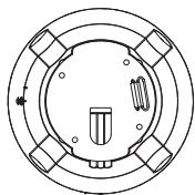
1. CEILING MOUNT BRACKET (SADT-101EC)
This bracket is used for installing the SmartDome camera in the plenum above the drop ceiling.
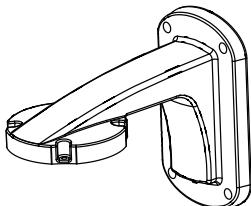
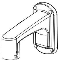
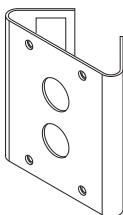
2.WALL MOUNT ADAPTOR (SADT-104WM)
This adaptor is used for installing the SmartDome camera on an indoor wall.
3. HANGING MOUNT ADAPTOR (SADT-100HM)
This adaptor is used for installing the SmartDome camera to an outdoor wall or a ceiling and used with CEILING MOUNT ADAPTOR(SADT-100CM).
4. OUTDOOR HOUSING (SHG-222)
This housing is used for installing the SmartDome camera to an outdoor wall or a ceiling.

※ To install and use OUTDOOR HOUSING, remove the Clear Dome from the Camera body before installation.
* When installing the OUTDOOR HOUSING to an outdoor wall, use WALL MOUNT ADAPTOR (SADT-103WM) to install it.
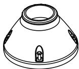
5. CEILING MOUNT ADAPTOR (SADT-100CM)
This adaptor is used for installing the OUTDOOR HOUSING(SH-222) and HANGING MOUNT ADAPTOR(SADT-100HM) for the SmartDome camera to a concrete ceiling. It is also used for installing the SmartDome camera with HANGING MOUNT ADAPTOR (SADT-100HM) to an indoor wall.
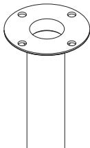
6. POLE MOUNT ADAPTOR (SADT-100PM)
This adaptor is used for installing the WALL MOUNT ADAPTOR (SADT-104WM/103WM) to a pole that is over 8 cm (2.76 in.) in diameter.
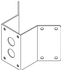
7. CORNER MOUNT ADAPTOR (SADT-110CM)
This adaptor is used for installing the WALL MOUNT ADAPTOR (SADT-104WM/103WM) to the edge of wall.
Installling the camera
-
Install the structure on the ceiling. (Refer to Installation reference for the Length of the structure)
-
Built in by the builder of the structure
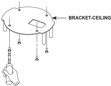
- Make a hole in the ceiling where the camera will be installed. (The hole should be about 185)

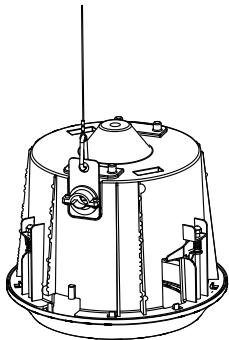
- Assemble the BRACKET-CEILING on the ceiling and screw the 4 bolts in.
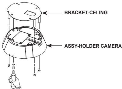
- Connect the various cables to the CAMERA ADAPTER.
- Match the BRACKET-CEILING and CAMERAADAPTER and use 4screws (PH M4 x 8) to assemble them.
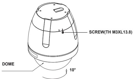
- Pull the safety wire from the case body, and assembly it to the camera holder.
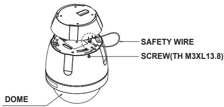
-
Match the 3 holes on the back of the CAMERA and the CONNECTOR and turn it right about 10 degrees. (Check the sound of LOCKING)
-
Use the screws (TH M3XL13.8) to connect the CAMERA and the ADAPTER so they don't move.
Camera Setup
Note
*SCC-C6433(P) does not support for WDR function.

Note
*Selectable languages may vary depending on sales region.
Note
- If the power is turned off after PRESET, AUTO PAN, SCAN, PATTERN function is activated and no other control is made, camera will do the same function after the power is turned on.
- When tilt position is over 90^ and menu-on command is received, pan will automatically rotate 180^ and tilt will be move to the corresponding position.
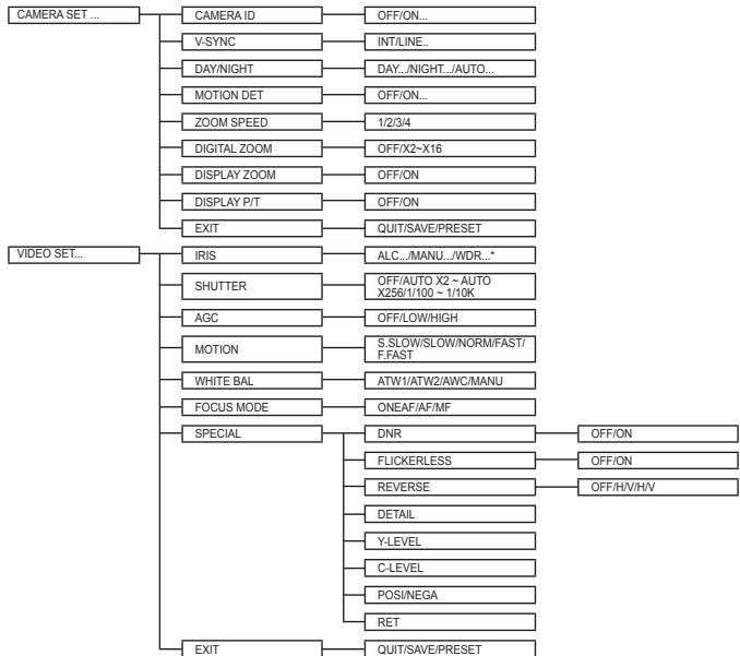
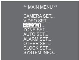
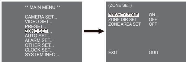
Use the controller to press the MENU selection key and the following screen will be displayed.
** MAIN MENU **
CAMERA SET...
VIDEO SET...
PRESET...
ZONE SET...
AUTO SET...
ALARM SET...
OTHER SET...
CLOCK SET...
SYSTEM INFO...

5
1
6
4
9
****
In case of ① , use UP/DOWN/LEFT/RIGHT/ENTER key for MENU setup. In case of ② , type in the 4 digit password first. If correct, the MENU selection screen like ① will be displayed and you will be able to set up MENU by pressing UP/DOWN/LEFT/RIGHT/ENTER key. Default password is "0123".
Camera setup
CAMERA ID
This CAMERA ID menu is used to assign a camera ID to this camera. If you press the Setup switch when the CAMERA ID menu is selected, the corresponding setup screen appears.
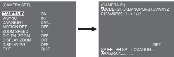
You can input a camera ID composed of alphabets, numbers, and special characters up to 20 characters long. The input camera ID can be displayed at the desired location when using the LOCATION... submenu. When you press the Setup switch in RET, the screen returns to the upper menu.
V-SYNC
In the V-SYNC menu, vertical synchronization can be selected. The vertical synchronization signal supported by the camera is the INT mode made by clock inside the camera and LINE mode adjusting vertical synchronization to the exterior power frequency.
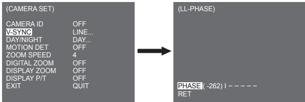
Select LINE and press Enter. You will see the LINE LOCK submenu where you can adjust the phase of the LINE LOCK. You can use the PHASE menu of the LINE LOCK submenu to assign as much PHASE as you want.
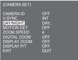
DAY/NIGHT
The DAY/NIGHT menu is used to configure the day and night related settings for this camera. This camera can turn the IR (Infrared) filter on or off.
DAY...
If you press the ENTER when the DAY... submenu is selected, the corresponding screen appears. You can set the values for [C-GAIN] when the DAY... submenu is selected. You can set the values for [AGC COLOR] and [AGC DETAIL] while the AGC menu is selected.
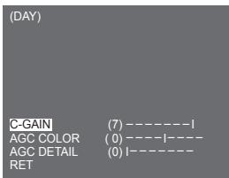
Note
When the value of AGC DETAIL becomes large, it also makes the noise stand out.
NIGHT...
If you press the ENTER when the NIGHT... submenu is selected, the corresponding screen appears.

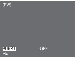
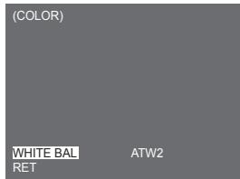
Even in night mode, you can see colour images in bright illumination. Therefore you can select any of [COLOR...] and [BW...]. In case of [COLOR...], you have to set the colour temperature for white balance. You can also specify the settings for red and blue colours on your own. In case of [BW...], the burst signals are output with the BW Composite Video signals when the BURST is set to [ON]. And no burst signals are output when the BURST is set to [OFF].
Note
When it is set to [NIGHT], [WHITE BAL] of the video set will be displayed as "----". You cannot adjust the settings manually.
When it is set to [COLOR] in the NIGHT mode, the white balance will be setting as the same value in [COLOR] mode.
AUTO...
This automatically converts the DAY mode to NIGHT mode and vice versa depending on illumination. In low illumination, it removes the IR filtering function to raise the sensitivity. Otherwise, it activates the IR filtering function to lower the sensitivity. If you press the ENTER when the AUTO... submenu is selected, the corresponding screen appears.
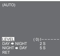
For this function, you can specify the level for each conversion between Day and Night.
Note
When the DAY/NIGHT is set to [AUTO...], the AGC is displayed with "---" so you cannot change its setting.
MOTION DET
The MOTION DET menu is used to configure the motion detection related settings. If you press the ENTER when [ON...] is selected in the MOTION DET menu, the corresponding screen appears.
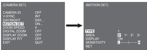
You cannot change the setting for type 2 because it is prefixed with the full screen. In case of 1 and 3, you can set the motion detection area on your own.
Those 3 types are like the following:
1. Window Type
The selected area is displayed with a box. The motion can be detected for the area only. You can manually set the motion detection area. You can use the UP/DOWN/LEFT/RIGHT Setup switch to set the size. To move to POSITION, press the switch. After setting the position using the UP/DOWN/LEFT/RIGHT Setup switch, press the Setup switch to move to the upper menu. To set the size and position for AREA, select any of 0, 1, 2, and 3.

Note
The selected window for AREA is displayed in white and the unselected one is displayed in black.
2.Label Type
The box-typed motion detection area is prefixed. The detected area is displayed with size and position changing. You cannot change AREA because it is displayed with "...
3. Block Type
The screen displays with small blocks. When a motion is detected in the selected blocks, the small blocks are displayed on the screen.
[PRESET]: The whole screen becomes the motion detection area.
[USER...] : You can manually set the motion detection area. Use the UP/DOWN/LEFT/RIGHT, ENTER to set the area. To erase the selected block, press the ENTER.

To select [RET], press UP key on the top block or press DOWN key on the bottom block and then press ENTER key to return a upper menu.
In order to set the motion detection area on your own, you have to specify the size and location for the area setting. When [ON] is selected in DISPLAY, the detected motion is displayed on the screen and the camera sends the Alarm Out signal. You can also assign the sensitivity for motion detection.
Note
- MOTION DET menu is not available for the first 5 seconds after operating the PAN/TILT/ZOOM/FOCUS/IRS functions.
- Since the motion detecting function depends on the brightness of selected area, it may dysfunction due to the different brightness between the background and object.
ZOOM SPEED
In the ZOOM SPEED, menu you can select the speed of the ZOOM Key (Tele/Wide).
| (CAMERA SET) | |
| CAMERA ID | OFF |
| V-SYNC | INT |
| DAY/NIGHT | DAY... |
| MOTION DET | OFF |
| ZOOM SPEED | 4 |
| DIGITAL ZOOM | OFF |
| DISPLAY ZOOM | OFF |
| DISPLAY P/T | OFF |
| EXIT | QUIT |
Use the Left/Right key in the ZOOM SPEED menu to select the speed.
1: Slowest speed
2: Low speed
3: High speed
4: Fastest speed
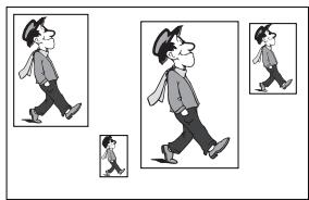
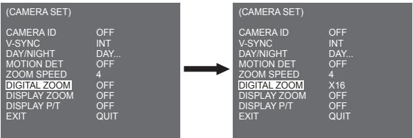
DIGITAL ZOOM
You may set up the digital zoom magnification ratio in the DIGITAL ZOOM menu. The magnification ratio ranges from OFF to 16. If you set Digital Zoom of the camera to max. 16 times, the mode will become the 32 time optical zoom and you will be able to enlarge a subject by max. 512 times. Use Left or Right to select a magnification ratio in the DIGITAL ZOOM menu.
OFF X2 X4 X6 X8 X10 X12 X14 X16
DISPLAY ZOOM
In DISPLAY ZOOM, you can display the ZOOM scale on the screen.
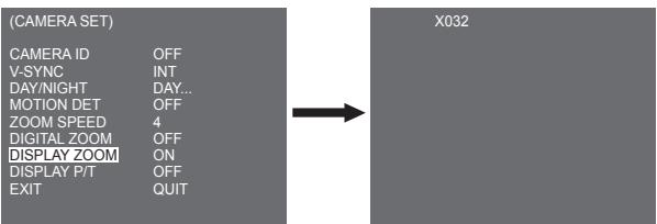
Note
If no change on the ZOOM scale is made for 3 seconds, the information window will disappear.
DISPLAY P/T
In DISPLAY P/T, you can display the position of Pan/Tilt on the screen.
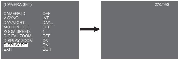
Note
- If no change on the Pan/Tilt position is made for 3 seconds, the information window will disappear.
- It allows an error range of ± 2^
EXIT
The EXIT menu is used to return to the MAIN menu.
- QUIT : Ignores the changed information and restores the saved information.
- SAVE : Saves the information of the setting condition of the menu.
- PRESET : Ignores the changed information and restores the initial factory defaults of the menu.
Video set
IRIS
There is a function to automatically adjust IRIS to the incoming light level. Owing to this function, you may set up the brightness level yourself. The ALC(Auto Light Control) menu allows you for video output level setup. The WDR(Wide Dynamic Range) menu allows you for setting up the level of WDR.
Note
SCC-C6433(P) does not support for WDR function.
MANU
Choose the ALC of the IRIS item and press the ENTER and set the submenu to the Video Output level and BLC will be shown. The Video Output Level can be set in the level item using the Left/Right keys.
BLC (Submenu of the ALC menu)
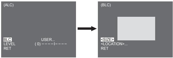
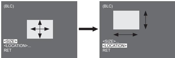
If you use a general camera to photograph a subject under backlight or bright illumination, the subject will be shown dark on the monitor due to the backlight. BLC(Back Light Compensation) is used to prevent such a backlight problem to secure distinct images under bright illumination. Using the Left, Right keys, you can set up [BOTTOM...], [TOP...], [LEFT...], [RIGHT...]. [CENTRE...] 5 preset areas and the [USER...] function that can directly set the areas. For example, for the items in the BLC menu, you can confirm the preset BOTTOM area by pressing the ENTER key in the [BOTTOM...] status.
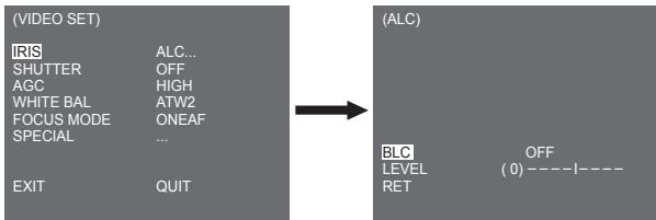

For items in the BLC menu, the user can set the area and location of the BLC area by pressing ENTER key after put the cursor on [USER...] using the Left, Right key. For AREA items, you can use the Up, Down, Left, Right key to designate the AREA, and then press the ENTER key. You can set the location for areas using the Up, Down, Left, Right key in the [LOCATION].
Use Left, Right key in the LEVEL menu to control the video output level (brightness).
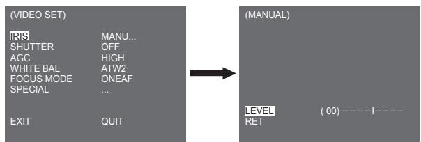
MANU
When you press the ENTER key after selecting MANU in the IRIS item, an additional screen appears in which you can set manually opening or closing the IRIS.
WDR
The WDR camera is a state-of-art technology to expand the screen profit, mostly effective when you photograph both indoor and outdoor. In short, this function provides you with the distinct reproduction of not only the indoor but also the outdoor. Press the ENTER to set up the WDR level.
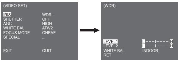
You can adjust the shutter speed in LEVEL 1 and the brightness in LEVEL 2. You can also select any of ALL, OUTDOOR, and INDOOR in WHITE BAL. In case of ALL, this camera controls both indoor and outdoor images.
Note
SCC-C6433(P) does not support for WDR function.
SHUTTER
You may designate both the fast electronic shutter speed and low electronic shutter speed in the SHUTTERTem. The fast electronic shutter supports 7 shutter speeds from 1/100(1/120) to 1/10K second to be used for the bright and fast video image. The AUTO slow electronic shutter supports 13 shutter speeds from x2 to x256 and sets the shutter speed to be slow In order to make the image on the screen more distinct and brighter when you photograph under dark illumination. If you want to sense the light brightness to control the shutter speed to the brightness automatically, select the AUTO slow shutter.
| (VIDEO SET) | |
| IRIS | ALC... |
| SHUTTER | OFF |
| AGC | HIGH |
| WHITE BAL | ATW2 |
| FOCUS MODE | ONEAF |
| SPECIAL | ... |
| EXIT | QUIT |
Keep pressing both Left and Right in the SHUTTER menu, the speed will change in the following sequence.
OFF AUTO X2 AUTO X4 AUTO X6 AUTO X8 AUTO X12 AUTOX16 AUTO X24 AUTO X32 AUTO X48 AUTO X64 AUTO X64 AUTO X96 AUTO X128 AUTO X256 OFF 1/120 1/250 1/500 1/1000 1/2000 1/4000 1/10K
※ In case the IRIS mode is set to WDR, only the following modes are available.
OFF AUTO X2 AUTO X4 AUTO X6 AUTO X8 AUTO X12 AUTOX16 AUTO X24 AUTO X32 AUTO X48 AUTO X64 AUTO X96 AUTO X128 AUTO X256
AGC
The AGC menu was designed to provide you with brighter screen supposed you photographed any subject in the dark resulting in less brighter image than regulated. AGC menu setup is available only when the SHUTTER menu is set to Fast Shutter or [Off]. Press Left/Right to go to [LOW] or [HIGH] and the AGC function will be activated. [LOW] is used to lower the maximum AGC GAIN and [HIGH] raise the maximum AGC GAIN.
(VIDEO SET)
IRIS
ALC...
SHUTTER
OFF
AGC
HIGH
WHITE BAL
ATW2
FOCUS MODE
ONEAF
SPECIAL
···
EXIT
QUIT
Note
When the COLOR/BW menu of the camera set is set to [AUTO...], AGC will be displayed as "----". You can't adjust the settings manually.
MOTION
The MOTION function is available only when the SHUTTERTen m is set to Slow Shutter AUTO, being composed of 5 steps, [S.SLOW], [SLOW], [NORM], [FAST], [F.FAST].
- [S.SLOW] reduces the amount of AGC as much as possible to monitor subjects with no immobility in the dark.
- [SLOW] reduces the amount of AGC to monitor subjects with little immobility in the dark.
- [NORM] sets the amount of AGC to the middle to monitor mobile subjects in the dark.
- [FAST] raises the amount of AGC to monitor fast subjects in the dark.
- [F.FAST] reduces the amount of AGC as much as possible to monitor very fast subjects in the dark. When the SHUTTER menu is set to AUTO, press Down to locate the cursor in the MOTION menu and press Left and Right for MOTION function setup. Press Left to the SLOW side and Right to the FAST side.
(VIDEO SET)
IRIS
ALC...
SHUTTER
AUTO X2
MOTION
F.FAST
WHITE BAL
ATW2
FOCUS MODE
ONEAF
SPECIAL
EXIT
QUIT
WHITE BAL
Lights are generally denoted as colour temperatures and expressed in Kelvin (K) units. The general light colour temperatures are shown below.
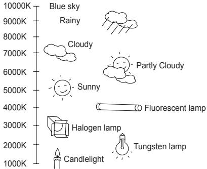
You can select one of four modes for white balance adjustment as follows:
- ATW1/ATW2(Auto-Tracing White Balance Mode): In these modes, the colour temperature is monitored continuously and thereby white balance is set automatically. The following are the approximate supported colour temperature ranges in these modes.
ATW1:2500K~9300K ^(*)1
ATW2: 2000K ~ 10000K (Mode recommended for sodium lighting) (*2)
1. If the colour temperature is out of this range in ATW1 mode, proper white balance may not be obtained. In that case, select ATW2 mode.
2. In ATW2 mode, if one colour is dominated in the shot area, the colour can be displayed differently. Therefore, select the mode which is appropriate for the environment.
- AWC+/(Auto-Tracing White Balance Control): In this mode, accurate white balance is obtained by pressing the ENTER while having a white paper in front of the camera. White Balance data will be maintained after set it once. AWC mode is best in locations where the colour temperature of light source is constant.
-
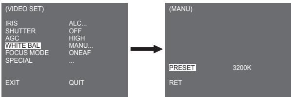
MANU: If WHITE BAL menu is set to MANU mode, the user can set the white Balance considering the current illumination. Select MANU menu and press the ENTER, the sub screen where you can select Manual White Balance will be shown. Use the left/right keys to select 3200K, 5600K or OFF(USER) mode in the PRESET menu.
-
3200K : Set colour temperature to 3200K
- 5600K : Set colour temperature to 5600K
- USER : Choose out a proper value from the RED and BLUE graph for colour and temperature setup.
Note
When the [DAY/NIGHT] menu of the camera set is set to [NIGHT], [WHITE BAL] will be displayed as "---". You cannot adjust the settings manually.
When it is set to [COLOR] in the [NIGHT] mode, the white balance will be setting as the same value in [COLOR] mode.
FOCUS MODE
In the FOCUS MODE MENU, the Focus method can be set to AF(Auto Focus), ONEAF(One Auto Focus), or MF(Manual Focus).
- AF : With AUTO FOCUS MODE, you can monitor the screen continuously and it will focus automatically. If you manually adjust the focus, it operates as the same in Manual Focus mode. It automatically sets the focus after the PAN/TILT/ZOOM movements.
- ONEAF: In the ONEAF mode, it automatically sets the focus after the zoom moves, and operates as the same in the MF mode if the zoom does not move.
- MF : In MANUAL FOCUS MODE the user adjusts the Focus manually.
(VIDEO SET)
IRIS
ALC...
SHUTTER
OFF
AGC
HIGH
WHITE BAL
ATW2
FOCUS MODE
AF
SPECIAL
···
EXIT
QUIT
Note
AF function may not possible with types of objects listed below. For such objects, focus manually.
- High intensity objects or objects illuminated with low lighting
- Objects shot through wet or dirty glass
- Pictures that are a mixture of distant and nearby objects
- White walls and other single-colour objects
- Venetian blinds and other horizontally striped objects
SPECIAL
The SPECIAL menu is used to configure the special settings for this camera. If you press the ENTER Key when ... is selected in the SPECIAL menu, the corresponding screen appears.
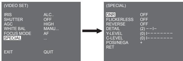
DNR
DNR(Digital Noise Reduction) function enables the picture to be reduced noise.
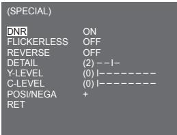
FLICKERLESS
When this is set to [ON], the shutter speed is set to 1/100 sec (for NTSC) or 1/120 sec (for PAL) to prevent from flickering by the discordance between vertical synchronization frequency and on-and-off frequency of the light.
REVERSE
It is used to mirror video signals horizontally, vertically, or both.
DETAIL
It is used to control the horizontal or vertical distinction.
Y-LEVEL
It is used to set the levels for the Sync signal and the entire brightness signal of the video signal.
C-LEVEL
It is used to set the levels for the Burst signal and the entire colour signal of the video signal.
POSI/NEGA
It is used to output as it is, or mirror the video brightness signal.
EXIT
The EXIT menu is used to return to the MAIN menu.
- QUIT : Ignores the changed information and restores the saved information.
- SAVE : Saves the information of the setting condition of the menu.
- PRESET : Ignores the changed information and restores the initial factory defaults of the menu.
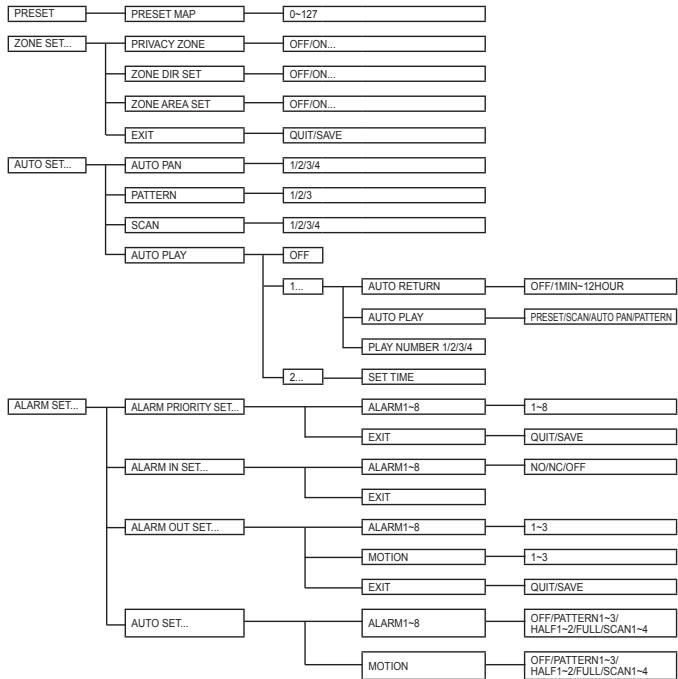
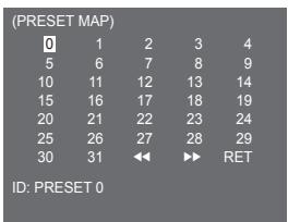
Preset
This is the menu that user sets the PAN/TILT location, Zoom/Focus, and screen condition, so the camera can monitor the presetting area on demand. A total of 128 presets are available
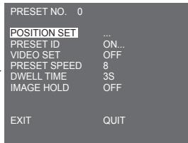
POSITION SET
From "POSITION SET..." press the ENTER key to get into the PAN/TILT, FOCUS/ZOOM SET screen to set the PAN/TILT location and FOCUS/ZOOM condition then press the ENTER key to return to a upper menu.
PRESET ID
This is the ID set up function for each PRESET. It can be set up to 12 characters using the left, right, up, and down keys. The ID location can be set in the submenu of "LOCATION..."
VIDEO SET
This is the screen setting function for each PRESET. For more details, refer to the descriptions in [VIDEO SET] menu.
PRESET SPEED
This function sets up the speed of PAN or TILT by 8 steps from 1(SLOW) to 8(FAST).
-
PRESET SPEED 1: Maximum PAN moving speed of 240^ /sec
-
PRESET SPEED 8 : Maximum PAN moving speed of 400^ /sec
DWELL TIME
This is a function setting for the DWELL TIME of the PRESET location in "SCAN" motion. It can set DWELL TIME From 1 ~ 60 Sec.
IMAGE HOLD
Pause the image when PRESET is in movement. If you set the [IMAGE HOLD] menu to [ON], the screen will be paused until PRESET finishes moving.
Zone set
- The ZONE SET menu includes the setup of PRIVACY ZONE, ZONE DIR SET, and ZONE AREA SET.

PRIVACY ZONE
Move PAN/TILT/ZOOM to select an area that can infringe someone privacy, then this function will hide the area if it can be involved in the photograph to protect his privacy. The number of area reaches up to 16.
Select a privacy zone number and press the ENTER key from the PRIVACY ZONE screen to enter the PRIVACY ZONE setup screen.
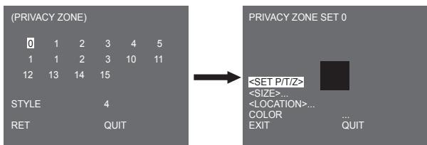
Note
- For the safer privacy protection, select about 10 % more than the actual area to hide when you set up the PRIVACY ZONE areal.
The mosaic of the recorded images is set to be the PRIVACY ZONE. The mosaic of the recorded images can not be recovered after recording.
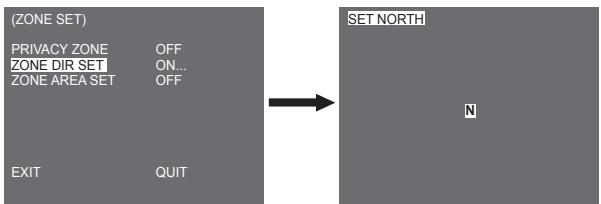
ZONE DIR SET
Press the ENTER key in the "ZONE DIR SET ON..." mode to enter the SET NORTH screen MAP. Move PAN to set the NORTH position and press the ENTER key. Based on the North position, the direction of N(North), NE(North-East), E(East), SE(South-East), S(South), SW(South-West), W(West), NW(North-West) is displayed whenever you move PAN.
ZONE AREA SET
Press the ENTER key to enter the ZONE AREA MAP screen from "ZONE AREA SET..." Select a ZONE AREA number from the ZONE AREA MAP screen and press the ENTER key to enter the ZONE AREA setup screen.
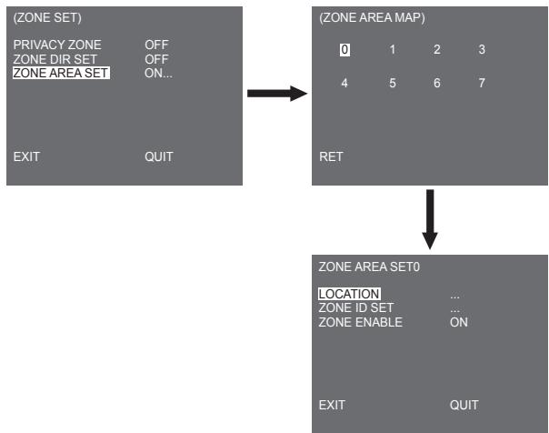
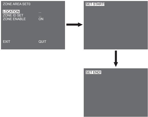
LOCATION
The [LOCATION...] menu designates the left/right LIMIT positions of ZONE AREA. Enter the setup screen to move PAN, then select a start position and press the ENTER key. Move PAN again to select an end position and press the ENTER key. Now, ZONE AREA setup is complete.
ZONE ID SET
This function is used to allocate as many as 12 IDs to each zone area. Use Left/Right/UP/DOWN for this purpose. You may select the ID position from the additional menu of [LOCATION...].
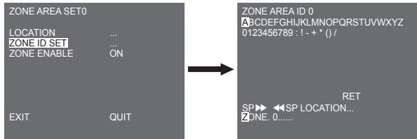
ZONE ENABLE
This function turns [ON] or [OFF] the ZONE AREA ID indication.
Auto set
The AUTO SET menu includes AUTO PAN, PATTERN, and SCAN and it is able to set up the AUTO PLAY motion.
AUTO PAN
After selecting the locations of two points (PAN/TILT) of START and END, it loops continuously in the set up SPEED. The number of AUTO PAN is up to 4.
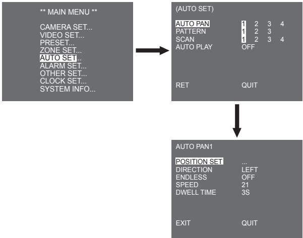
POSITION SET
The menu [POSITION SET ...] sets the Start / End position of AUTO PAN. Return to the settings screen and set the desired START position for PAN/TILT, and then press the ENTER key. And, set the END position for the PAN/TILT. Press the ENTER key to finish the setup for AUTO PAN Start/End positions.
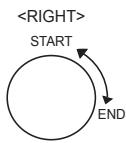
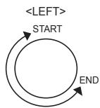
DIRECTION
This sets up the movement direction of the START to END location (PAN location standard)
ENDLESS
This is a 360-degree rotation function that stops for the DWELL TIME only in the START and END positions without running between the START and END positions. It can be set to [ON] or [OFF].
SPEED
This is a setting function for movement speed setup. It can be set from STEP1 to STEP64.
DWELL TIME
This is a function for setting up the time to stay in the START and END position. It can be individually set to 1-59 sec or 1-60 min.
PATTERN
This is a replay function so that the MANUAL functions such as PAN, TILT, ZOOM, and FOCUS are played for 2 minutes.
Note
- When the PATTERN is saved/executed, the PAN/TILT is operated with PROPORTIONAL ON, TURBO OFF.
- If the SSC-1000 or SSC-2000 is used when uploading/downloading the menu setup, reset the PATTERN because it may be different with the first setting.
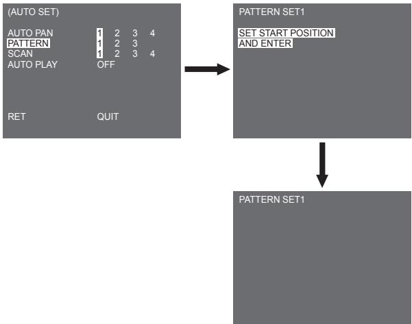
PATTERN can be set up to 3. Choose 1, 2, or 3 with the Left/Right key in the [PATTERN SET] and press the ENTER key to get into the PATTERN set up screen. From the moment "PATTERN SET 1" is gone for 2 minutes, it memorizes the MANUAL movements and after 2 minutes, it will return to a upper menu. If you want to finish set up before the 2-minutes ends, press the ENTER key.
SCAN
SCAN sets the direction of PRESET movement during SCAN operation. The number of SCAN is up to 4.
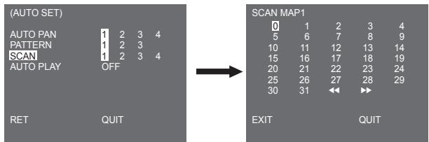
If you enter the SCAN screen, [SCAN MAP] will be displayed. Move the cursor to the number marked * where PRESET is saved and press the ENTER key and [S] will appear and a PRESET will be included in SCAN.
AUTO PLAY
If you press the ENTER switch when the [1...] submenu is selected, the corresponding screen appears.
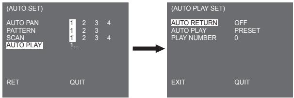
AUTO RETURN
This menu sets up the time during which AUTO PLAY repeats.
AUTO PLAY
This function sets up the motion which will be repeatedly performed by the camera whenever the time set by AUTO RETURN elapses. It covers SCAN, AUTO PAN, PATTERN, and PRESET setup.
PLAY NUMBER
This menu allocates a number to the motion set by AUTO PLAY. The numbers range from 1 to 4 for SCAN AND AUTO PAN, 1 to 3 for PATTERN, and 0 to 127 for PRESET.
If you press the ENTER switch when the [2...] submenu is selected, the corresponding screen appears.
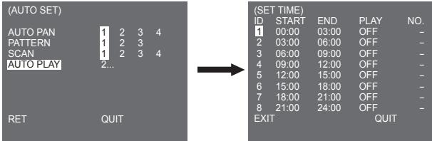
Set the start/end time and select PRESET, PATTERN, AUTO PAN or SCAN to set up. Preset function will be in the action according to the start time. It can be set up to 8 presets.
Note
- After running AUTO PLAY function, the position of the camera does not return back to the original position.
Alarm set
It consists of 8 ALARM INPUTs and 3 ALARM OUTs. It can sense an ALARM input from exterior SENSORS and it performs with PRESET or PATTERN function and outputs the ALARM OUT signals. Alarm operation time depends on the Preset Dwell time corresponding to the alarm and whether AUTO is involved.
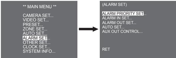
ALARM PRIORITY SET
This sets the priority of the 8 ALARM inputs so ALARM can work corresponding to the priority. The priority of the DEFAULT is ALARM1, ALARM2, ALARM3, ALARM4, ALARM5, ALARM6, ALARM7, ALARM8. If the ALARM is working at the same time and the priority is the same, it will operate according to the DEFAULT priority. While the ALARM is working, it cannot detect MOTION.
ALARM IN SET
This sets the input TYPE to [NO] (Normal Open), [NC] (Normal Close), or [OFF] depending on the features of the SENSOR connected.
ALARM OUT SET
Each ALARM input corresponds to one of the 3 ALARM OUT.
AUTO SET
This menu designates what to do at the time of ALARM input. Once an alarm is given, the camera will shortly move to the PRESET position corresponding to the respective alarm as follows. PRESET1 to ALARM1-8 PRESET9 to MOTION.
After DWELL TIME at a PRESET position, PATTERN or SCAN will be in action according to the AUTO SET setup.
Setup of OFF/1/2/3/HALF1/HALF2/FULL/SCAN1~4 is available.
OFF dues not perform PATTERN or SCAN after moved to PRESET and each menu has its own function as follows.
PATTERN 1~3: Preset PATTERN action
HALF1: Continuous operation of PATTERN1 + PATTERN2
HALF2:Continuous operation of PATTERN2 + PATTERN3
FULL: Continuous operation of all the above
SCAN 1~4: Scanning as set
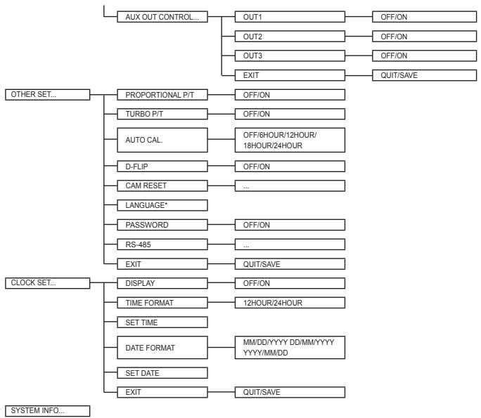
AUX OUT CONTROL
This sets the ALARM OUT motion to continue or act only when the ALARM is working. If it is set to OFF the ALARM OUT motion will operate only when the ALARM is working. (Active "Low"), and if it's set to ON, the ALARM OUT will always operate regardless of the ALARM.
Other set
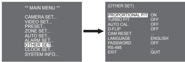
PROPORTIONAL P/T
This function controls the PAN/TILT speed to the ZOOM magnification ratio during the manual operation of PAN/TILT. If you set PROPORTIONAL P/T to ON, the PAN/TILT speed will increase in the ZOOM WIDE mode and decrease in the ZOOM TELE mode even in the same manual operation.
TURBO P/T
This function doubles up the speed of PAN/TILT movement by manual operation of PAN/TILT. The speed may go up to 180^ /sec (PAN).
AUTO CAL.
This function turns on or off Auto Calibration. SCC-C6435(P)/6433(P) has the Auto Calibration function to improve the precision of LENS and PAN/TILT motor. You may set to OFF/6H/12H/18H/24H. Without user's key input for the time designated by the user, A.C. will appear on the screen while initializing LENS and PAN/TILT.
D-FLIP
When D-FLIP is off, TILT movement ranges from 0^ to 90^ .
When D-FLIP is on, TILT movement ranges from 0^ to 180^ .
When D-FLIP is on, images mirror vertically and horizontally in the area beyond TILT 90^ .
CAM RESET
CAM RESET clears all the settings made so far and restores the factory default settings.
[CAMERA RESET?] message appears when you select CAM RESET. Select [CANCEL] to return to the menu setup display or select OK to restore the factory default settings.
Note
Be careful when performing a CAM RESET operation, as it deletes all setup values.
LANGUAGE
This function selects a language for MENU setup. You can change the OSD language using the Left/Right Setup key.
Note
Selectable languages may vary depending on sales region.
Password
This function selects or cancels the MENU setup password. Press the ENTER key at the state of PASSWORD ON, and the following screen will appear for password setup.
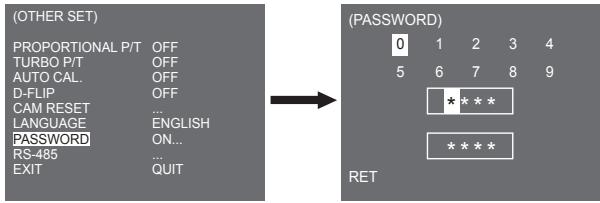
Press Up/Down/Left/Right key to locate the cursor on a number and press the ENTER key for password setup. After you finish inputting the 4 digits password and the 2nd row of the 4 digits PASSWORD input screen, input the selected password again for reassurance. If correct, the cursor will move to RET. Press the ENTER key at RET, and the selected password will be saved, returning to the OTHER SET screen. Default password is '0123'.
RS-485
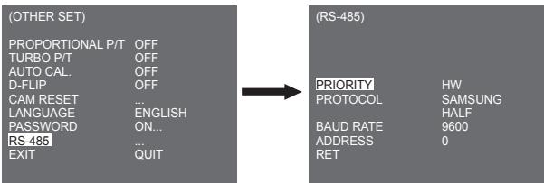
[PRIORITY] menu is used to set the priority between hardware and software. If you select [HW], it operates according to the value of the camera hold adapter. If you select [SW], you can manually set [PROTOCOL], [BAUD RATE], [ADDRESS] for RS-485.
Clock set
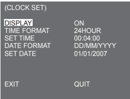
DISPLAY: Sets to [ON] to display the clock on the screen.
TIME FORMAT: Supports 2 type of formats: 24 Hours and 12 Hours (AM/PM).
SET TIME: Sets the time.
- DATE FORMAT: Supports 3 types of formats: YYYY/MM/DD, DD/MM/YYYY, and MM/DD/YYYY.
SET DATE: Sets the date.
System info
This menu allows you to check S/W version, communication protocol, baud rate, and address of the camera.
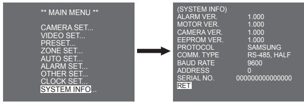
- ALARM, MOTOR, CAMERA and EEPROM VER. may change without notice.
Shortcut keys
SSC-1000 or SSC-2000 Controller supports the following short keys.
| Function | Key |
| CAMERA SET... | |
| DAY/NIGHT - DAY | [PRESET] + [1] + [2] + [8] + [Enter] |
| DAY/NIGHT - NIGHT | [PRESET] + [1] + [2] + [9] + [Enter] |
| DAY/NIGHT - AUTO | [PRESET] + [1] + [3] + [0] + [Enter] |
| VIDEO SET... | |
| IRIS - WDR | [PRESET] + [1] + [3] + [1] + [Enter] |
| IRIS - ALC | [PRESET] + [1] + [3] + [2] + [Enter] |
| FOCUS MODE - ONEAF | [PRESET] + [1] + [3] + [5] + [Enter] |
| FOUCS MODE - MF | [PRESET] + [1] + [3] + [4] + [Enter] |
| FOUCS MODE - AF | [PRESET] + [1] + [3] + [3] + [Enter] |
| ALARM SET... | |
| AUX OUT CONTROL... | |
| OUT1 - ON | [PRESET] + [1] + [3] + [6] + [Enter] |
| OUT1 - OFF | [PRESET] + [1] + [3] + [7] + [Enter] |
| OUT2 - ON | [PRESET] + [1] + [3] + [8] + [Enter] |
| OUT2 - OFF | [PRESET] + [1] + [3] + [9] + [Enter] |
| OUT3 - ON | [PRESET] + [1] + [4] + [0] + [Enter] |
| OUT3 - OFF | [PRESET] + [1] + [4] + [1] + [Enter] |
| OTHER SET... | |
| PROPORTIONAL P/T - ON | [PRESET] + [1] + [4] + [2] + [Enter] |
| PROPORTIONAL P/T - OFF | [PRESET] + [1] + [4] + [3] + [Enter] |
| TURBO P/T - ON | [PRESET] + [1] + [4] + [4] + [Enter] |
| TURBO P/T - OFF | [PRESET] + [1] + [4] + [5] + [Enter] |
| D-FLIP - ON | [PRESET] + [1] + [4] + [6] + [Enter] |
| D-FLIP - OFF | [PRESET] + [1] + [4] + [7] + [Enter] |
| AUTO RETURN *1) | [PRESET] + [1] + [4] + [8] + [Enter] |
| AUTO Calibration | [PRESET] + [1] + [4] + [9] + [Enter] |
| CAM RESET | [PRESET] + [1] + [5] + [0] + [Enter] |
Other keys than AUTO CAL. and AUTO RETURN, upon execution, shall be applied to the MENU setup process.
*1) The use of AUTO RETURN will be available only when the function equivalent to AUTO PLAY, a sub menu of AUTO SET has been built in.
SCC-6435

Product Specifications
| Item | Details | |||||
| Product Type | Zoom lens single body WDR SmartDome CAMERA | |||||
| Power Input | SCC-C6433/C6435 : AC 24V ± 10% (60Hz ± 0.3Hz) SCC-C6433P/C6435P : AC 24V ± 10% (50Hz ± 0.3Hz) | |||||
| Power Consumption | SCC-C6433(P) : 19W SCC-C6435(P) : 20W | |||||
| Broadcasting Type | SCC-C6433(5) : NTSC STANDARD COLOUR SYSTEM SCC-C6433(5)P : PAL STANDARD COLOUR SYSTEM | |||||
| Image Device | SCC-C6433/C6433P : 1/4" Super HAD IT CCD SCC-C6435/C6435P : 1/4" ExView HAD PS CCD | |||||
| Effective Pixels | SCC-C6433/C6435 : 768(H) × 494(V) SCC-C6433P/C6435P : 752(H) x 582(V) | |||||
| Scanning line Frequency | SCC-C6433/C6435 Horizontal : 15, 734 Hz(INT) / 15, 750 Hz(L/L) Vertical : 59.94 Hz(INT) / 60 Hz(L/L) SCC-C6433P/C6435P Horizontal : 15, 625 Hz(INT) / 15, 625 Hz(L/L) Vertical : 50 Hz(INT) / 50 Hz(L/L) | |||||
| Synchronization Mode | INT/LINE LOCK | |||||
| Resolution | Horizontal : 540(Colour) / 570(BW) Vertical : 350 TV LINES | |||||
| S/N Ratio | Approx. 50dB | |||||
| Item | Details | |||||
| Min. Scene illumination | Condition | SCC-C6433(P) | SCC-C6435(P) | |||
| Illumination | Sens-up | Colour | B/W | Colour | B/W | |
| 50IRE | Off | 2.0 | 0.20 | 1.2 | 0.12 | |
| 30IRE | Off | 1.2 | 0.12 | 0.7 | 0.07 | |
| 15IRE | Off | 0.6 | 0.06 | 0.3 | 0.03 | |
| 50IRE | x256 | 0.008 | 0.0008 | 0.005 | 0.0005 | |
| 30IRE | x256 | 0.005 | 0.0005 | 0.003 | 0.0003 | |
| 15IRE | x256 | 0.002 | 0.0002 | 0.001 | 0.0001 | |
| WDR | SCC-C6433/C6433P : N/ASCC-C6435 : x128SCC-C6435P : x160 | |||||
| Signal Output | COMPOSITE VIDEO OUT : 1.0 Vp-p 75 ohms/BNC | |||||
| Lens | One body; 32xZoom lensFocal length : 3.55 to 113 mmAperture : F1.69(Wide), F4.17(Tele)- MOD(Minimum Object Distance) : 2.5m | |||||
| PAN Function | PAN range : 360° EndlessPreset Pan Speed : 400° /sec, maximum- Manual Pan Speed : 0.1° ~ 180°/sec (64Step) | |||||
| TILT Function | TILT range : 0° ~ 180°Preset Tilt Speed : 200°/sec, maximum- Manual Tilt Speed : 0.1° ~ 90°/sec (64Step) | |||||
| REMOTE CONTROL | - Tele/Wide(ZOOM), Near/Far(FOCUS),Iris Open/Close, Pan/Tilt, MENURS-485 HALF/FULL Duplex, RS-422 | |||||
| ALARM | Alarm Inputs : 8 INAlarm Outputs : 3 OUT (Open collector 1 relay) | |||||
| Item | Details | |||||
| Operation Temperature | -10°C ~ +50°C | |||||
| Operation Humidity | ~90% | |||||
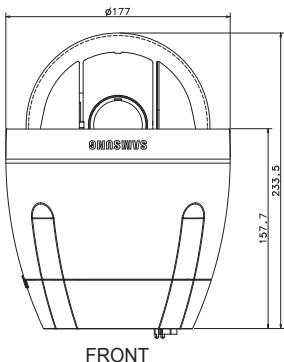
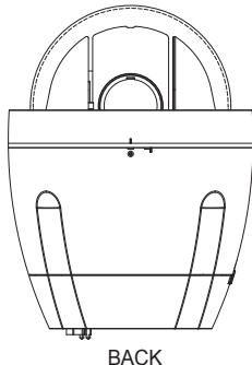
| SIZE | DOME : 147.65(ø), Outline : 177(ø) x 194.3(H) | |||||
| Weight | NET : 2,544g GROSS : 3,545g | |||||
| Lives of Main Parts | - Slip-ring: Rotated 10,000,000 times | |||||
Memo
Correct Disposal of This Product
(Waste Electrical & Electronic Equipment)
(Applicable in the European Union and other European countries with separate collection systems)
This marking shown on the product or its literature, indicates that it should not be disposed with other household wastes at the end of its working life. To prevent possible harm to the environment or human health from uncontrolled waste disposal, please separate this from other types of wastes and recycle it responsibly to promote the sustainable reuse of material resources.
Household users should contact either the retailer where they purchased this product, or their local government office, for details of where and how they can take this item for environmentally safe recycling.
Business users should contact their supplier and check the terms and conditions of the purchase contract. This product should not be mixed with other commercial wastes for disposal.
SAMSUNG
Uberi these Anleitung. 8
Produktübersicht 8
Hauptfunktionen 8
Komponenten 8
ÜBERPRÜFEN DER KOMPONENTEN IN
DER VERPACKUNG 8
ALARM EIN PROGRAMM 66
ALARM AUS PROGRAMM 66
AUTO PROGRAMM 66
AUX AUS KONTROLLE 66
WeitereProgramme 67
PROPORTIONAL P/T 67
TURBO P/T 67
AUTOKALIBRIER. 67
DIGITAL-FLIP 68
KAMRESET 68
SPRACHE 68
PASSWORT 69
RS-485 70
Uhr Einstellung 70
System Info 71
Schnelltasten 72
B: SAMSUNG FULL-DUPLEX
- ZONE SET (BÖLGGE AYARI) menusu, PRIVACY ZONE, ZONE DIR SET ve ZONE AREA SET ayarini icerir.
PRIVACY ZONE
PATTERN 1~3: PATTERN islemine basin
HALF1: PATTERN1 + PATTERN2'nin surekli calismasi
HALF2:PATTERN2+PATTERN3'unSureklicalmasi
FULL: Tüm yukaridakilerin surekli calismasi
SCAN 1~4: Ayarlandi gibi tarama
AUX OUT CONTROL
- WARNING
- ·WARNING
- CAUTION
- Important Safety Instructions
- Contents
- Overview 8
- Installation 10
- Camera Setup 28
- Video set 42
- Preset 53
- Auto set 60
- Alarm set 65
- Other set 67
- Clock set 70
- Product Specifications 75
- About this guide
- Product overview
- Note
- Main features
- Components
- CHECKING COMPONENTS IN THE PACKAGE
- NAMES OF EACH PART
- Before installation
- THINGS TO KEEP IN MIND DURING INSTALLATION AND USE
- Initial setting
- CAMERA ADDRESS SETUP
- SETTING COMMUNICATION PROTOCOL
- BAUD RATE SETTING
- SETTING RS-422A/RS-485 TERMINATION
- Adapter cable connection
- Cable connection
- Installation precautions
- Separately sold products for installation
- CEILING MOUNT BRACKET (SADT-101EC)
- 2.WALL MOUNT ADAPTOR (SADT-104WM)
- HANGING MOUNT ADAPTOR (SADT-100HM)
- OUTDOOR HOUSING (SHG-222)
- CEILING MOUNT ADAPTOR (SADT-100CM)
- POLE MOUNT ADAPTOR (SADT-100PM)
- CORNER MOUNT ADAPTOR (SADT-110CM)
- Installling the camera
- Camera Setup
- CAMERA ID
- V-SYNC
- DAY/NIGHT
- DAY...
- NIGHT...
- AUTO...
- MOTION DET
- Window Type
- 2.Label Type
- Block Type
- ZOOM SPEED
- DIGITAL ZOOM
- DISPLAY ZOOM
- DISPLAY P/T
- EXIT
- Video set
- IRIS
- MANU
- BLC (Submenu of the ALC menu)
- WDR
- SHUTTER
- AGC
- (VIDEO SET)
- MOTION
- WHITE BAL
- FOCUS MODE
- SPECIAL
- DNR
- FLICKERLESS
- REVERSE
- DETAIL
- Y-LEVEL
- C-LEVEL
- POSI/NEGA
- Preset
- POSITION SET
- PRESET ID
- PRESET SPEED
- DWELL TIME
- IMAGE HOLD
- Zone set
- PRIVACY ZONE
- ZONE DIR SET
- ZONE AREA SET
- LOCATION
- ZONE ID SET
- ZONE ENABLE
- Auto set
- AUTO PAN
- DIRECTION
- ENDLESS
- SPEED
- PATTERN
- SCAN
- AUTO PLAY
- AUTO RETURN
- PLAY NUMBER
- Alarm set
- ALARM PRIORITY SET
- ALARM IN SET
- ALARM OUT SET
- AUX OUT CONTROL
- Other set
- PROPORTIONAL P/T
- TURBO P/T
- AUTO CAL.
- D-FLIP
- CAM RESET
- LANGUAGE
- Password
- RS-485
- Clock set
- System info
- Shortcut keys
- Product Specifications
- Memo
- Correct Disposal of This Product
- WeitereProgramme 67
- Uhr Einstellung 70
Brand : SAMSUNG
Model : SCC-C6435P
Category : Surveillance Camera