ZOOM - Range hood FABER - Free user manual and instructions
Find the device manual for free ZOOM FABER in PDF.
| Product type | Range hood |
| Brand | FABER |
| Model | ZOOM |
| Power supply | 120 V, 60 Hz, 15 A, dedicated circuit |
| Installation type | Ceiling mount, recirculation only |
| Minimum distance (electric surface) | 24 in (61 cm) |
| Minimum distance (gas surface) | 30 in (76 cm) |
| Motor | Variable speed motor |
| Speeds | Multi-speed + intensive (6 min) |
| Special functions | Delay shut-off (30 min), 24h cycle (10 min/h) |
| Lighting | Integrated, replaceable bulbs (contact customer service) |
| Remote control | Yes, LR03 AAA batteries (not included) |
| Grease filter | Self-supporting metal, dishwasher safe |
| Charcoal filter | Replace every 4 months (ref. FILTER1) |
| Maintenance | Grease filter every 2 months, charcoal filter every 4 months |
| Safety | Safety microswitch, shutdown in case of overload |
| Warranty | 1 year (parts and labor) |
Frequently Asked Questions - ZOOM FABER
User questions about ZOOM FABER
0 question about this device. Answer the ones you know or ask your own.
Ask a new question about this device
Download the instructions for your Range hood in PDF format for free! Find your manual ZOOM - FABER and take your electronic device back in hand. On this page are published all the documents necessary for the use of your device. ZOOM by FABER.
USER MANUAL ZOOM FABER
natural_image
Technical line drawing of a cylindrical industrial or scientific apparatus with vertical supports and a central vent (no text or symbols)Installation Instructions
Use and Care Information
READ AND SAVE THESE INSTRUCTIONS BEFORE YOU START INSTALLING THIS RANGEHOOD
WARNING: - TO REDUCE THE RISK OF A RANGE TOP GREASE FIRE:
a) Never leave surface units unattended at high settings. Boilovers cause smoking and greasy spillovers that may ignite. Heat oils slowly on low or medium setting.
b) Always turn hood ON when cooking at high heat or when flambeing food (i.e. Crepes Suzette, Cherries Jubilee, Peppercorn Beef Flambé).
c) Clean ventilating fans frequently. Grease should not be allowed to accumulate on fan or filter.
d) Use proper pan size. Always use cookware appropriate for the size of the surface element.
WARNING: - TO REDUCE THE RISK OF INJURY TO PERSONS IN THE EVENT OF A RANGE TOP GREASE FIRE, OBSERVE THE FOLLOWING*:
a) SMOTHER FLAMES with a close-fitting lid, cookie sheet, or metal tray, then turn off the burner. BE CAREFUL TO PREVENT BURNS. If the flames do not go out immediately EVACUATE AND CALL THE FIRE DEPARTMENT.
b) NEVER PICK UP A FLAMING PAN - You may be burned.
c) DO NOT USE WATER, including wet dishcloths or towels - a violent steam explosion will result.
d) Use an extinguisher ONLY if:
-
You know you have a Class ABC extinguisher, and you already know how to operate it.
-
The fire is small and contained in the area where it started.
-
The fire department is being called.
-
You can fight the fire with your back to an exit.
* Based on "Kitchen Firesafety Tips" published by NFPA
WARNING - TO REDUCE THE RISK OF FIRE OR ELECTRIC SHOCK, do not use this fan with any solid-state speed control device.
WARNING - TO REDUCE THE RISK OF FIRE, ELECTRICAL SHOCK, OR INJURY TO PERSONS, OBSERVE THE FOLLOWING:
- Use this unit only in the manner intended by the manufacturer.
- If you have any questions, contact the manufacturer.
- Before servicing or cleaning unit, switch power off at service panel and lock the service disconnecting means to prevent power from being switched on accidentally.
- When the service disconnecting means cannot be locked, securely fasten a prominent warning device, such as a tag, to the service panel.
CAUTION: For General Ventilating Use Only. Do Not Use To Exhaust Hazardous or Explosive Materials and Vapors.
WARNING - TO REDUCE THE RISK OF FIRE, ELECTRICAL SHOCK, OR INJURY TO PERSONS, OBSERVE THE FOLLOWING:
- Installation Work And Electrical Wiring Must Be Done By Qualified Person(s) In Accordance With All Applicable Codes And Standards, Including Fire-Rated Construction.
-
Sufficient air is needed for proper combustion and exhausting of gases through the flue (chimney) of fuel burning equipment to prevent backdrafting. Follow the heating equipment manufacturer's guideline and safety standards such as those published by the National Fire Protection Association (NFPA), and the American Society for Heating, Refrigeration and Air Conditioning Engineers (ASHRAE), and the local code authorities.
-
When cutting or drilling into wall or ceiling, do not damage electrical wiring and other hidden utilities.
- Ducted fans must always be vented to the outdoors.
ALL WALL AND FLOOR OPENINGS WHERE THE RANGEHOOD IS INSTALLED MUST BE SEALED. This rangehood requires at least 24" of clearance between the bottom of the rangehood and the electric cooking surface or countertop and at least 30" of clearance between the bottom of the rangehood and the gas cooking surface or countertop. This hood has been approved by UL at this distance from the cooktop. Consult the cooktop or range installation instructions given by the manufacturer before making any cutouts. MOBILE HOME INSTALLATION The installation of this rangehood must conform to the Manufactured Home Construction and Safety Standards, Title 24 CFR, Part 3280 (formerly Federal Standard for Mobile Home Construction and Safety, Title 24, HUD, Part 280). See Electrical Requirements.
ELECTRICAL REQUIREMENTS
A 120 volt, 60 Hz AC-only electrical supply is required on a separate 15 amp fused circuit. A time-delay fuse or circuit breaker is recommended. The fuse must be sized per local codes in accordance with the electrical rating of this unit as specified on the serial/rating plate located inside the unit near the field wiring compartment.
ELECTRICAL INSTALLATION WITH WIRING BOX
THIS UNIT MUST BE CONNECTED WITH COPPER WIRE ONLY. Wire sizes must conform to the requirements of the National Electrical Code, ANSI/NFPA 70 - latest edition, and all local codes and ordinances. Wire size and connections must conform with the rating of the appliance. Copies of the standard listed above may be obtained from:
National Fire Protection Association
Batterymarch Park
Quincy, Massachusetts 02269
This appliance should be connected directly to the fused disconnect (or circuit breaker) through flexible, armored or nonmetallic sheathed copper cable. Allow some slack in the cable so the appliance can be moved if servicing is ever necessary. A UL Listed, 1/2" conduit connector must be provided at each end of the power supply cable (at the appliance and at the junction box).
When making the electrical connection, cut a 1 1/4" hole in the wall. A hole cut through wood must be sanded until smooth. A hole through metal must have a grommet.

WARNING
- Electrical ground is required on this rangehood.
- If cold water pipe is interrupted by plastic, nonmetallic gaskets or other materials, DO NOT use for grounding.
• DO NOT ground to a gas pipe. - DO NOT have a fuse in the neutral or grounding circuit. A fuse in the neutral or grounding circuit could result in electrical shock.
- Check with a qualified electrician if you are in doubt as to whether the rangehood is properly grounded.
- Failure to follow electrical requirements may result in a fire.
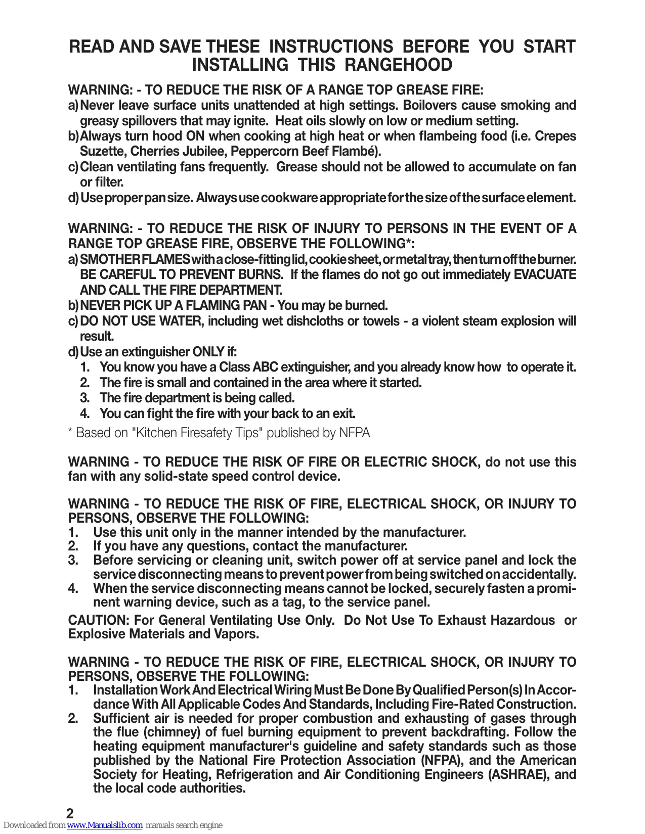
MAIN PARTS
text_image
12g 14 4 3 12c 15 1 2 30Components
| Ref. | Qty. | Product Components |
| 1 | 1 | Hood Body, complete with:Controls, Light, Filters, Motor. |
| 2 | 1 | Hood support plate |
| 3 | 1 | Cable seal |
| 4 | 1 | Cable raceway |
| 14 | 1 | Pawl |
| 15 | 4 | Knobs |
| 30 | 1 | Remote Control |
| Ref. | Qty. | Installation Components |
| 12c | 1 | Srews 1/8" x 3/8" |
| 12g | 1 | Screws for pawl |
| Qty. | Documentation | |
| 1 | Instruction Manual |
Available Accessories
Activated
Charcoal
Filter sku #;
FILTER1
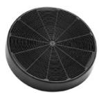
When used in recirculation mode, To Reduce the Risk of Fire and Shock use only conversion kit Model FILTER 1."
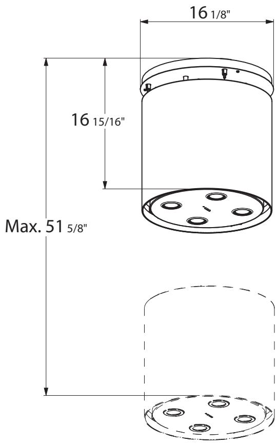
RANGEHOOD DIMENSIONS
text_image
16 1/8" 16 15/16" Max. 51 5/8"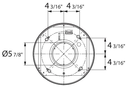
text_image
4 3/16" 4 3/16" Ø5 7/8" 4 3/16" 4 3/16"
text_image
Min. 24" Min. 30"INSTALLATION
This hood is designed to be mounted on the ceiling/on a shelf, above a free-standing Hob (min. 24"), in:
- Recirculation version: Internal recirculation.
Sequence of operations - Installation
Preparing for installation:
- Drilling the Ceiling/Shelf and Fixing the support plate
- Connections
- Fitting the hood body
- Functional Check
- Disposal of Packaging
natural_image
Illustration of a tool and screwdriver in a mechanical assembly (no text or symbols)Fitting the Limiter pawl
1
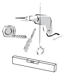
natural_image
Technical line drawings of a mechanical component with two views: top shows a flat plate with mounting holes and a circular base with concentric rings (no text or symbols)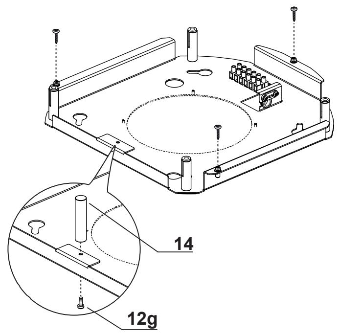
text_image
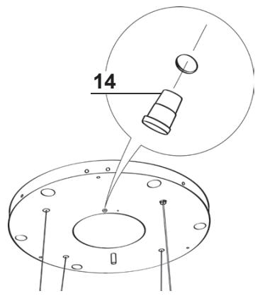
14 12g- Unfasten the 3 screw that join the parts of the Plate (of different shapes and/or sizes) using the wrench provided.
• Take the Pawl (14) and fix it to the plate on the bracket in the position indicated in the figure, using the screw provided (12g).
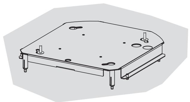
Ceiling/Shelf drilling and Plate Fixing CEILING/SHELF DRILLING
2
natural_image
Diagram of a mechanical or laboratory setup with a cylindrical component and a base plate, showing internal components and motion lines (no text or symbols)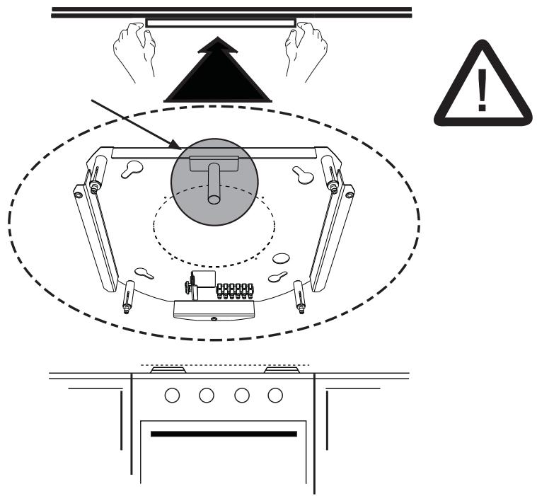
text_image
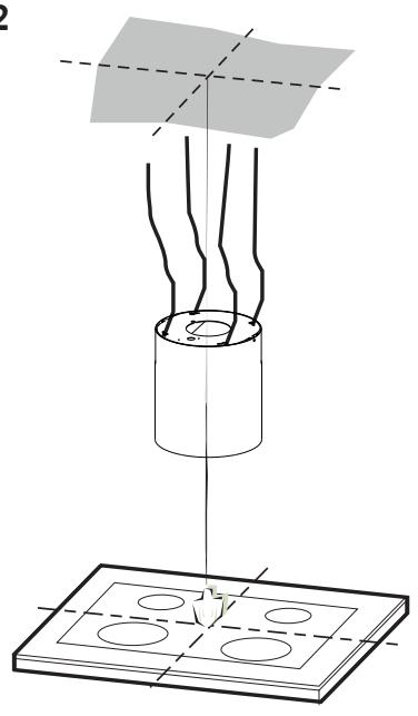
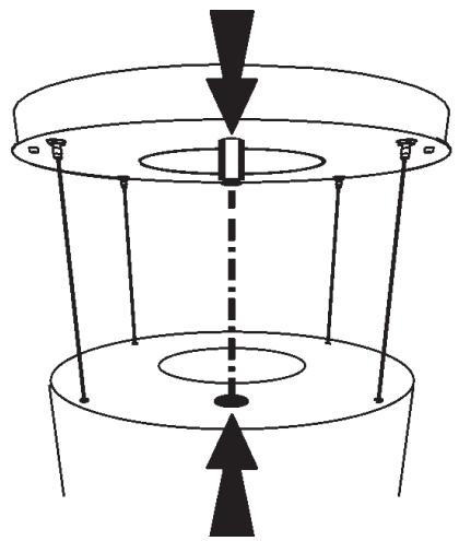
Safety warning diagram showing hand protection, warning symbol, and safety instructions for a device setup.Use a plumb-line and mark the centre of the cooking hob on the Support Ceiling/Shelf.
- Rest the plate against the ceiling/shelf, taking care to keep the limit pawl that has just been fitted in a position facing the installer and the cooking hob (the limit pawl must not be confused with the other 4 used to fix the steel cables that move the Hood).
- Mark on the ceiling the centres of the holes in the plate.
- Drill the following points:
- Ceilings in solid concrete: As per concrete plugs used.
- Ceilings in hollow bricks with 13/16" resistance thickness: Drill a hole ø 6/16" (insert Plugs not supplied).
- Ceilings with Wood Beams: As per Wood Screws used (not supplied).
- Wooden shelf, with a resistant thickness of 9/16": drill a hole 4/16".
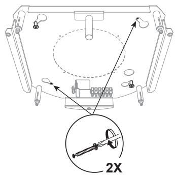
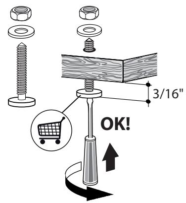
Insert two screws, crossing them and leaving 3/16" from the ceiling:
• for solid concrete, concrete plugs, not provided.
- for hollow bricks with approx. 13/16" resistance thickness, screws not provided.
• for wooden beams, wood screws, not provided.
- for wooden shelves, screws with washers and nuts, not provided.
text_image
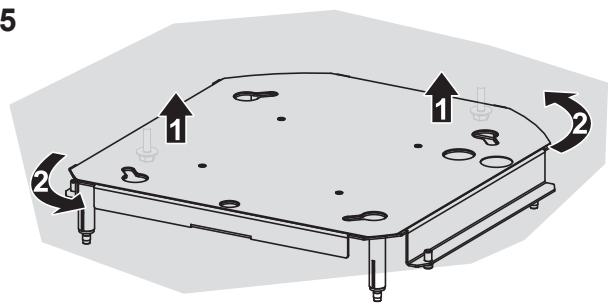
3 4XFIXING THE PLATE
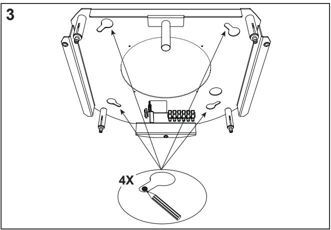
- Lift up the fixing plate, taking care to ensure that the limit pawl is positioned frontally.
- Fit the slots onto the two screws previously inserted in the ceiling, and turn until they are at the centre of the adjustment slot.
- Tighten the two screws completely and screw in the other two provided; before locking the screws completely it is possible to make adjustments by turning the piece, making sure that the screws do not come out of the adjustment slot.
- The unit must be securely fastened both due to the weight of the Hood and the stress caused by occasional sideways pressure on the Appliance when in position. Once the unit has been fixed, make sure that the plate is stable.
- In all cases where the Ceiling is not sufficiently strong at the point of suspension, the Installation technician must strengthen it with suitable plates and counterplates, anchored to structurally sound elements.
4

text_image
4X 4X 2X5
text_image
5 1 2 2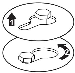
flowchart
graph TD
    A["Stage 1: Hexagonal nut"] --> B["Stage 2: Looped loop"]
    style A fill:#f9f,stroke:#333
    style B fill:#bbf,stroke:#333
natural_image
Technical line drawing of a mechanical component with mounting holes and a flat base (no text or symbols)6

text_image
Technical diagram showing a mechanical assembly with labeled components and a magnified inset of a 2X tool.
text_image
4X
natural_image
Technical line drawing of a mechanical component with mounting holes and mounting feet (no text or symbols)7

text_image
3/16" OK!
text_image
3/16" OK!
text_image
3/16" OK!Use only screws and small parts in support of the hood.
Warning: Failure to install the screws or fixing device in accordance with these instructions may result in electrical hazards.
8

natural_image
Pure diagram of a mechanical or electrical component with no text, numbers, or symbolsMinimum distances must be kept between the hood and cooking surface.
natural_image
Illustration of two people installing or adjusting a large cylindrical device on an induction cooktop, with one person climbing and the other standing on a ladder (no text or symbols present)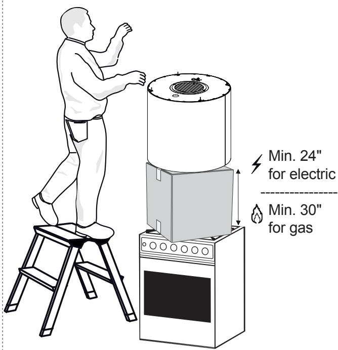
text_image
Min. 24" for electric Min. 30" for gasCONNECTING HOOD-PLATE CABLES
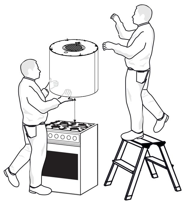
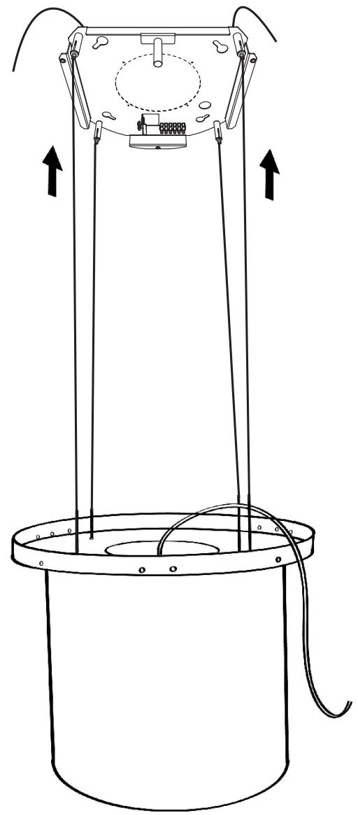
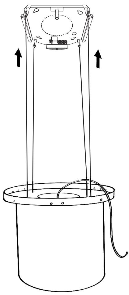
N.B. Before continuing with installation it is necessary to move the hood to a height of at least 24" from the cooker hob, using a support or the assistance of another person.

This is essential, as the hood cables must necessarily be connected to the plate fitted to the ceiling without the weight of the hood bearing on the structure.
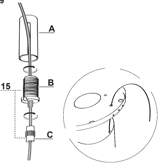
The cable fixing system is made up of 3 parts:
- Threaded Pawls (a) already mounted on the ceiling plate.
- Cable clamp screws (b) provided (15).
- Safety knobs (c) provided (15).
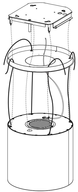
- Pass the cables connected to the hood canopy into the respective holes in the plate cover, after dismantling.
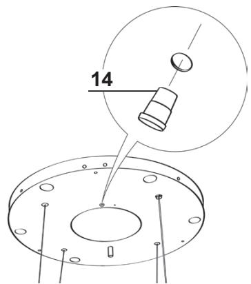
- Insert the cable raceway (14) in the opening on the plate cover and pass the hood power supply cable through it.
Warning: Do not break or remove the clamp fixing the power cable to the Hood.
- Attention to the direction of the plate fixed to the ceiling (the limit pawl on the plate fastened to the ceiling has a corresponding hole on the plate cover and on the hood canopy).
11
natural_image
Technical line drawing of a cylindrical device with internal components and wiring, no text or symbols present9
text_image
A B C 1510

text_image
14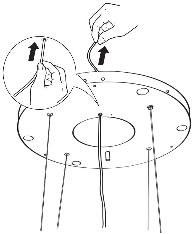
natural_image
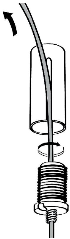
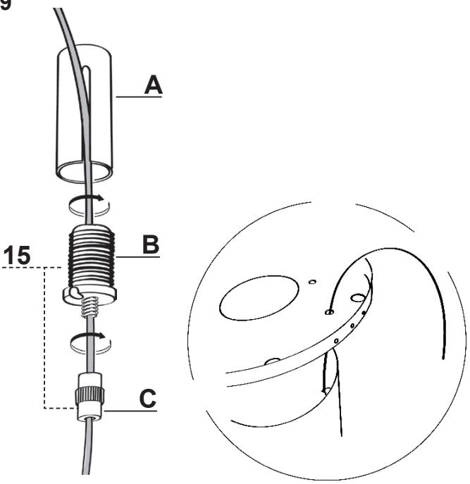
Illustration of hands connecting wires to a circular component with pins, showing a magnified inset (no text or symbols)- Insert the cables into the safety knobs (c) with the thread at the top (Fig.12).
- Insert the cables into the cable clamp screws (b) (Fig.12).
- Pass the cables through the slots in the threaded pawls (a) and screw the cable locking screws (b) to the pawls themselves (Fig.13).
- When the operation has been completed the result must be as shown in the figure for all 4 cables (Fig.13).
- At this point we have all 4 cables connected to the plate.
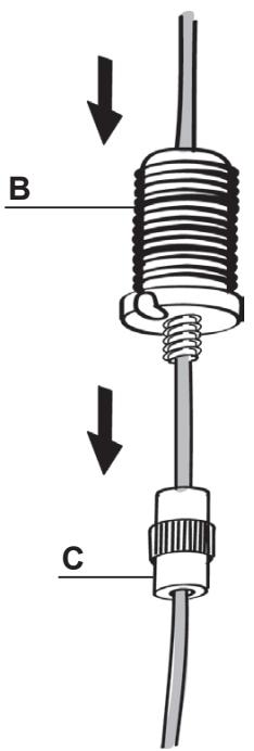
Bring the cables under tension by pushing them upwards so that they slide inside the cable clamp screw and slide out of the slot in the threaded pawl.
This is possible because the cable clamp screw has a system that, if mounted properly, allows the cables to slide inside it in one direction only, and prevents it from sliding in the other direction.
Attention, the cables all have the same length to facilitate the operation of the final level. The front left cable must not be slacker than the others.
12
text_image
B C14
natural_image
Technical line drawing of a cylindrical mechanical device with attached components and directional arrows indicating motion (no text or symbols)13

natural_image
Diagram of a mechanical device with a coiled spring and rotating cable, showing motion direction (no text or symbols)
natural_image
Technical line drawing of a mechanical assembly with an inset showing a cable inserted into a component (no text or symbols present)LEVELLING THE HOOD
- The hood mobile unit must be levelled to allow the movement to operate properly.
- The hood is levelled by adjusting the safety pawls.
- Rest a spirit level on the hood.
- When the safety knobs are pressed upwards, movement of the hood is “unlocked”. By inserting or extracting the cable from the cable clamp screw it is possible to make adjustments that allow the mobile hood body to be levelled.
- Once the hood has been set level, the safety knobs must be tightened again.
Warning:
- Please check that all 4 cables are stretched.
- Please check that all 4 cables were not damaged during installation.
- Please cut the excess part of each cable. The excess part must be shorter than 13/16".
- It must be remembered that the minimum distance between the hood and the cooking hob must be 24" from the electric cooking surface and 30" from the gas cooking surface.
15
natural_image
Technical line drawing of a cylindrical mechanical device with vertical supports and internal components, no text or symbols present.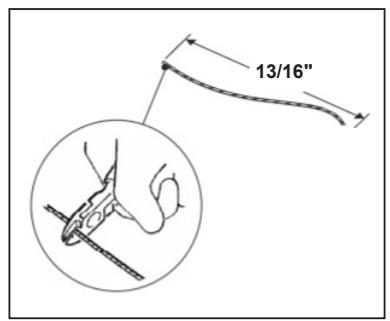
text_image
13/16"
text_image
2 1
text_image
0.0°Connections
Non-Ducted Recirculation Only
- Open the lighting unit by pulling on the notch provided.
- Remove the grease filters.
- Make sure that the Activated charcoal filters has been fitted.
CONNECTING THE HOOD POWER SUPPLY CABLE
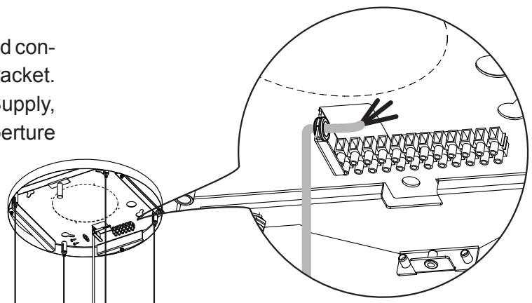
- Take the power supply cable from hood and connect the end with exposed wires into the bracket.
- Connect the Hood to the Mains Power Supply, inserting a bipolar switch with a contact aperture of at least 3 mm.
- Remove the Grease filters (see paragraph “Maintenance”) and make sure that the Power cable has been properly inserted into the Suction fan socket.
- At this point it is possible to connect up the hood, and Ceiling lighting assembly to the power supply using the respective power cables.
text_image
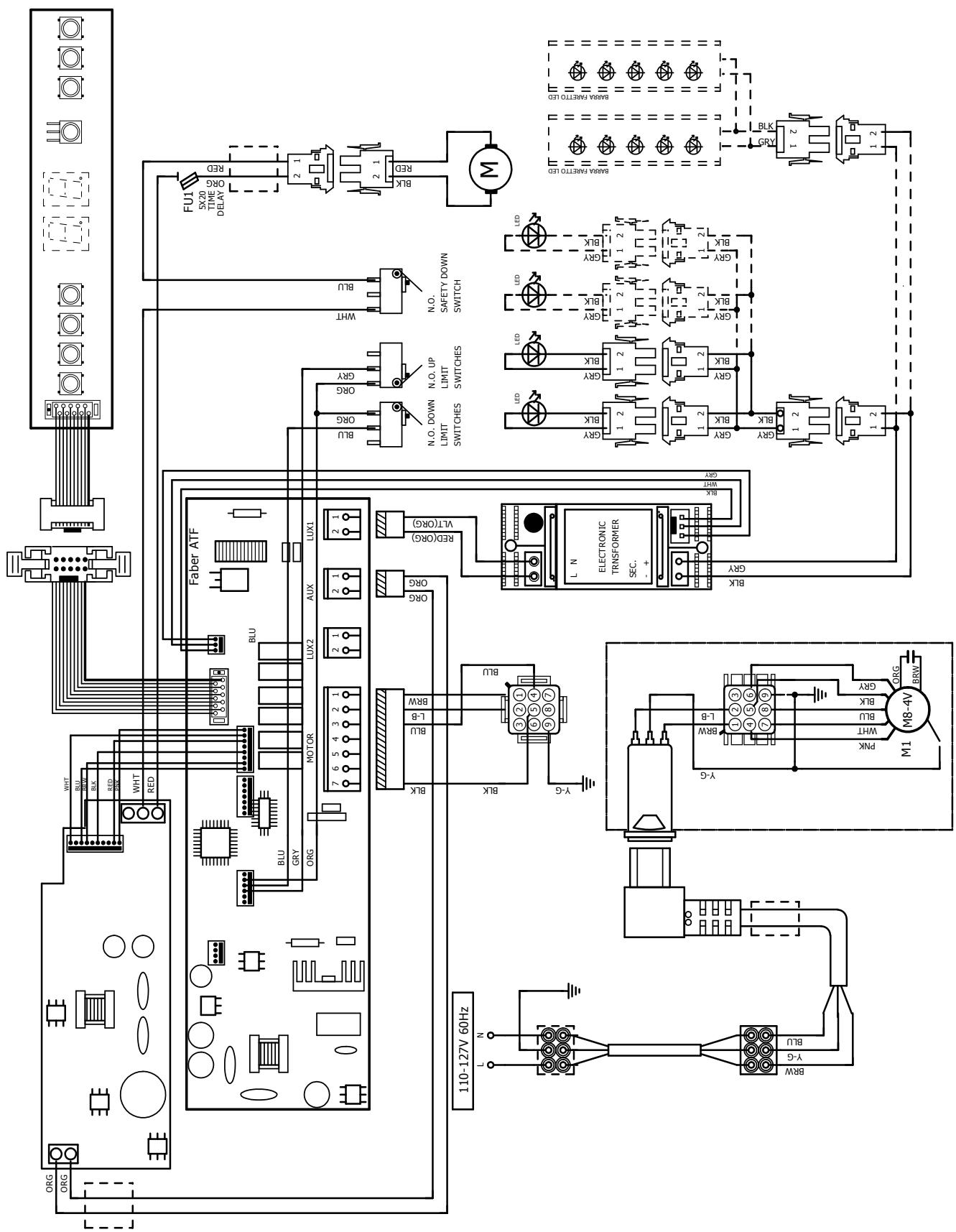
d con- jacket. supply, erturePlease refer to the wiring diagram provided on the appliance, near Field Wiring Terminal.
FITTING THE PLATE COVER
- Close the plate cover using the 3 screws removed previously and the wrench provided.
natural_image
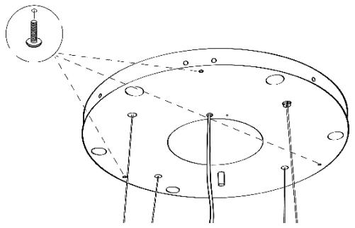
Technical diagram of a mechanical assembly with concentric circular components and mounting holes (no text or labels)• Take the cable clamp 3 provided.
- Insert the Power cable in the Cable clamp 3 and screw it to the plate using one of the Screws 12c provided.
- Finally, check that the power supply cable is properly locked, checking that when the mobile unit rises up towards the ceiling, it positions itself over the mobile unit and does not come out from the edge of the hood.
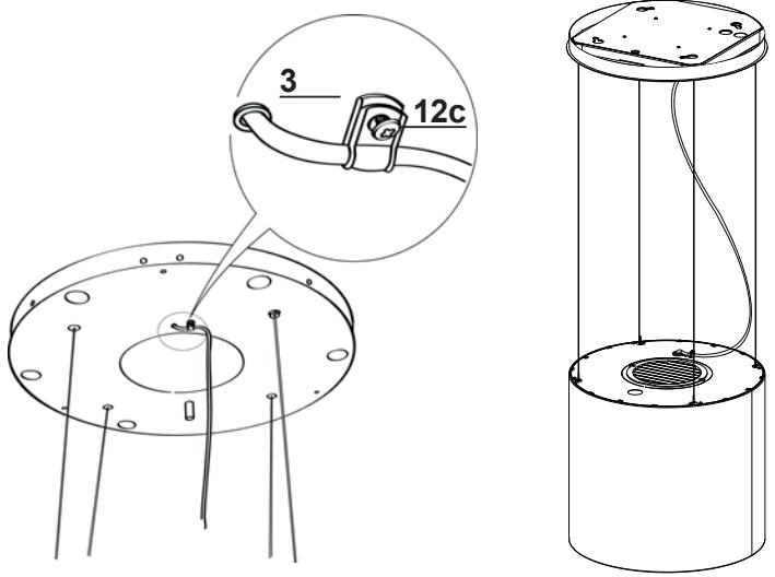
text_image
3 12cCONTROL PANEL
For Best Results
Start the rangehood several minutes before cooking to develop proper airflow. Allow the rangehood to operate for several minutes after cooking is complete to clear all smoke and odors from the kitchen.
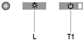
text_image
L T1| Button | Function | Display |
| L | Turns the lights On/Off. | - |
| T1 | Hood Down / ExtendedPress for 2 seconds to raise the Hood.Press briefly to turn the Motor On/Off. | On/Off. |
| Hood Near CeilingPress once: The Hood lowers.Press a second time: The Hood Stops.When the movement has been completed the motor turns on at Speed two. | On/Off. |
Warning: The Hood controls only control the Hood functions. The Lighting unit has a completely separate power supply and a separate switch.
THE ELECTRONIC CONTROL SYSTEM RECOGNIZES AND SIGNALS TWO TYPES OF FAULT.
| Led T1 | |
| Slow flashing | Current absorption threshold exceeded:If an overload condition occurs, the fault is signalled by LED T1 on the keyboard flashing once every 2 seconds. Check that nothing is blocking normal hood movements.The signal remains active until a new hood open/close command is given. |
| Rapid flashing | Hood opening safety microswitch tripped:If the safety microswitch trips, the fault is signalled by LED T1 on the keyboard flashing quickly (once every 250 ms). This means that the hood has passed the microswitch...... Call Technical Assistance!You can continue to use the hood’s light and motor functions while this fault is active. Whenever the motor is on, LED T1 will continue to flash, indicating that the fault is still present. |
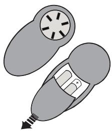
REMOTE CONTROL
The appliance can be controlled using a remote control powered by a 1.5 V carbon-zinc alkaline batteries of the standard LR03-AAA type (not included).
- Do not place the remote control near to heat sources.
- Used batteries must be disposed of in the proper manner.
natural_image
Illustration of a pair of medical or surgical devices with no visible text or symbolsControl panel

| Button | Function | Display |
| Turns the Motor On/Off. | - | |
| Hood Closed:- Press the button briefly to start lowering the hood.- It will stop when the button is pressed again.When the movement has been completed the motor will start at speed 2. | - | |
| Hood Open:- Press and hold for 2 seconds to activate raising of the hood, which stops when it reaches the stop.- Press (briefly) to stop the movement (before the stop is reached).- Press again briefly to turn the motor on/off.- Press and hold for 2 seconds to start raising of the hood.- If the motor is on, it will first stop the motor and then start the movement. | - | |
| + | Decreases the speed of the Motor. | - |
| - | Increases the speed of the Motor. | - |
| i | INTENSIVE- This can only be activated with the hood lowered and when the delay or 24h functions are not active.- Activates Intensive speed from any other speed.To disable it, simply press the same button again or turn the motor off.- Intensive speed is timed to run for 6 minutes. At the end of the 10 minutes the system will automatically return to the speed that was set before. | The led on the motor button (on the hood controls) will flash once a second. |
| Press briefly for the Delay Function:Can only be activated if the Intensive or 24h function is not active.Activates and deactivates total shutdown of the hood (motor+lights) after 30 minutes:To disable the Delay, simply press the button again or turn the motor off. | The led on the motor button (on the hood controls) will flash once every 0.5 seconds. | |
| Press and hold for 2 sec. for the 24H Function:Can only be activated if the Intensive or Delay function is not active.Activates and deactivates the 24H function for 10 minutes every hour, for 24 hours. After this time it is deactivated. | The led on the motor button (on the hood controls) will flash once every 2 seconds. | |
| Turns the Hood lights On/Off. | - |
MAINTENANCE
GREASE FILTER
The filter must be cleaned every 2 months of operation, or more frequently for particularly heavy usage, and can be washed in a dishwasher.
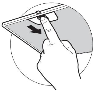
CLEANING METAL SELF-SUPPORTING GREASE FILTER
- Open the lighting unit by pulling on the notch.
- Remove the filter one by one pushing it towards the back side of the hood unit and simultaneously pulling downwards.
- Any kind of bending of the filter has to be avoided when washing it. Before fitting it again into the hood make sure that it is completely dry.
- When fitting the filter into the hood pay attention that they are mounted in correct position the handle facing outwards.
- Replace the lighting unit.
natural_image
Illustration of a hand pressing a device on a screen with an arrow indicating left motion (no text or symbols present)ACTIVATED CHARCOAL FILTER
(Recirculation Version)
This cannot be washed or regenerated, and must be changed approximately once every 4 months, or more frequently in the case of particularly intensive use.
CHANGING
- Open the light unit.
- Remove grease filter.
- Remove the saturated Activated Charcoal Filters, as indicated (A).
• Fit the new Filters, as indicated (B). - Fit the anti-grease filter and the Light Unit back into position.
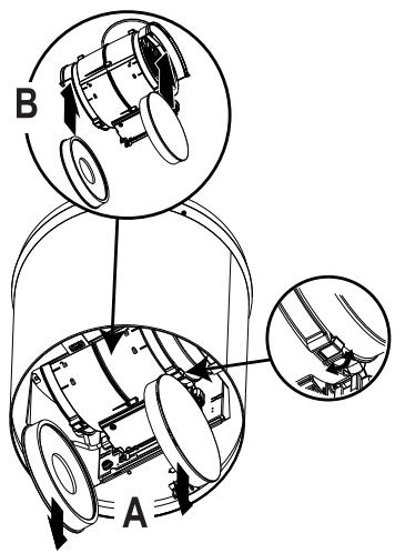
text_image
B ALIGHTING UNIT
- For replacement contact technical support ("to purchase contact technical support").
Wiring Diagram
flowchart
graph TD
    A["AC Source"] --> B["FU1"]
    B --> C["FLUX"]
    C --> D["BLX"]
    D --> E["RCD"]
    E --> F["Switch"]
    F --> G["BLUX"]
    G --> H["BLUX"]
    H --> I["BLUX"]
    I --> J["BLUX"]
    J --> K["BLUX"]
    K --> L["BLUX"]
    L --> M["BLUX"]
    M --> N["BLUX"]
    N --> O["BLUX"]
    O --> P["BLUX"]
    P --> Q["BLUX"]
    Q --> R["BLUX"]
    R --> S["BLUX"]
    S --> T["BLUX"]
    T --> U["BLUX"]
    U --> V["BLUX"]
    V --> W["BLUX"]
    W --> X["BLUX"]
    X --> Y["BLUX"]
    Y --> Z["BLUX"]
    Z --> AA["BLUX"]
    AA --> AB["BLUX"]
    AB --> AC["BLUX"]
    AC --> AD["BLUX"]
    AD --> AE["BLUX"]
    AE --> AF["BLUX"]
    AF --> AG["BLUX"]
    AG --> AH["BLUX"]
    AH --> AI["BLUX"]
    AI --> AJ["BLUX"]
    AJ --> AK["BLUX"]
    AK --> AL["BLUX"]
    AL --> AM["BLUX"]
    AM --> AN["BLUX"]
    AN --> AO["BLUX"]
    AO --> AP["BLUX"]
    AP --> AQ["BLUX"]
    AQ --> AR["BLUX"]
    AR --> AS["BLUX"]
    AS --> AT["BLUX"]
    AT --> AU["BLUX"]
    AU --> AV["BLUX"]
    AV --> AW["BLUX"]
    AW --> AX["BLUX"]
    AX --> AY["BLUX"]
    AY --> AZ["BLUX"]
    AZ --> BA["BLUX"]
    BA --> BB["BLUX"]
    BB --> BC["BLUX"]
    BC --> BD["BLUX"]
    BD --> BE["BLUX"]
    BE --> BF["BLUX"]
    BF --> BG["BLUX"]
    BG --> BH["BLUX"]
    BH --> BI["BLUX"]
    BI --> BJ["BLUX"]
    BJ --> BK["BLUX"]
    BK --> BL["BLUX"]
    BL --> BM["BLUX"]
    BM --> BN["BLUX"]
    BN --> BO["BLUX"]
    BO --> BP["BLUX"]
    BP --> BQ["BLUX"]
    BQ --> BR["BLUX"]
    BR --> BS["BLUX"]
    BS --> BT["BLUX"]
    BT --> BU["BLUX"]
    BU --> BV["BLUX"]
    BV --> BW["BLUX"]
    BW --> BX["BLUX"]
    BX --> BY["BLUX"]
    BY --> BZ["BLUX"]
    BZ --> CA["BLUX"]
    CA --> CB["BLUX"]
    CB --> CC["BLUX"]
    CC --> CD["BLUX"]
    CD --> CE["BLUX"]
    CE --> CF["BLUX"]
    CF --> CG["BLUX"]
    CG --> CH["BLUX"]
    CH --> CI["BLUX"]
    CI --> CJ["BLUX"]
    CJ --> CK["BLUX"]

FABER
FABER CONSUMER WARRANTY & SERVICE
All Faber products are warranted against any defect in materials or workmanship for the original purchaser for a period of 1 year from the date of original purchase (requires proof of purchase). This warranty covers labor and replacement parts. Faber, at its option, may repair or replace the product or components necessary to restore the product to good working condition. To obtain warranty service, contact the dealer from whom you purchased the range hood, or the local Faber distributor. If you cannot identify a local Faber distributor, contact us at (508) 358-5353 for the name of a distributor in your area.
The following is not covered by Faber's warranty:
- Service calls to correct the installation of your range hood, to instruct you how to use your range hood, to replace or repair house fuses or to correct house wiring or plumbing.
- Service calls to repair or replace range hood light bulbs, fuses or filters. Those consumable parts are excluded from warranty coverage.
- Repairs when your range hood is used for other than normal, single-family household use.
- Damage resulting from accident, alteration, misuse, abuse, fire, flood, acts of God, improper installation, installation not in accordance with electrical or plumbing codes or Faber documentation, or use of products not approved by Faber.
- Replacement parts or repair labor costs for units operated outside the United States or Canada, including any non-UL or C-UL approved Faber range hoods.
- Repairs to the hood resulting from unauthorized modifications made to the range hood.
- Expenses for travel and transportation for product service in remote locations and pickup and delivery charges. Faber range hoods should be serviced in the home.
THIS WARRANTY DOES NOT ALLOW RECOVERY OF INCIDENTAL OR CONSEQUENTIAL DAMAGES, INCLUDING, WITHOUT LIMITATION, DIRECT, INDIRECT, INCIDENTAL, SPECIAL OR CONSEQUENTIAL DAMAGES, PERSONAL INJURY/WRONGFUL DEATH OR LOST PROFITS FABER WARRANTY IS LIMITED TO THE ABOVE CONDITIONS AND TO THE WARRANTY PERIOD SPECIFIED HEREIN AND IS EXCLUSIVE. EXCEPT AS EXPRESSLY SPECIFIED IN THIS AGREEMENT, FABER DISCLAIMS ALL EXPRESS OR IMPLIED CONDITIONS, REPRESENTATIONS, AND WARRANTIES INCLUDING, WITHOUT LIMITATION, ANY IMPLIED WARRANTIES OF MERCHANTABILITY OR FITNESS FOR A PARTICULAR PURPOSE.
This warranty gives you specific legal rights that may vary from state to state.
Model#:
Serial #:
January 4, 2016
VEUILLEZ LIRE ET CONSERVER LA PRÉSENTE NOTICE AVANT DE COMMENCER L'INSTALLATION DE LA HOTTE DE CUISINE
AVERTISSEMENT:-POUR RÉDUIRE LE RISQUE D'UN FEU DE GRAISSE SUR LA TABLE DE CUISSON :
National Fire Protection Association
Batterymarch Park
- Electrical ground is required on this rangehood.
- If cold water pipe is interrupted by plastic, nonmetallic gaskets or other materials, DO NOT use for grounding.
• DO NOT ground to a gas pipe. - DO NOT have a fuse in the neutral or grounding circuit. A fuse in the neutral or grounding circuit could result in electrical shock.
- Check with a qualified electrician if you are in doubt as to whether the rangehood is properly grounded.
- Failure to follow electrical requirements may result in a fire.
PIÈCES PRINCIPALES

text_image
12g 14 4 3 12c 15 1 2 30Composants
text_image
16 1/8" 16 15/16" Max. 51 5/8"
text_image
4 3/16" 4 3/16" Ø5 7/8" 4 3/16" 4 3/16"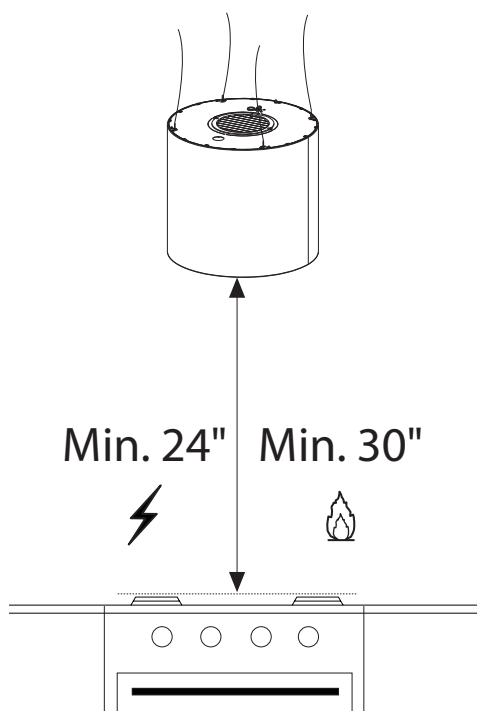
text_image
Min. 24" Min. 30"INSTALLATION
natural_image
Illustration of a hand using a screwdriver to cut a screwdriver into a workpiece (no text or symbols present)natural_image
Technical line drawing of a mechanical component with mounting holes and support legs (no text or symbols)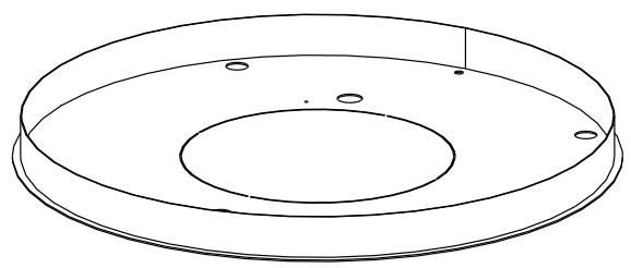
natural_image
Technical line drawing of a circular mechanical component with concentric rings and mounting holes (no text or symbols)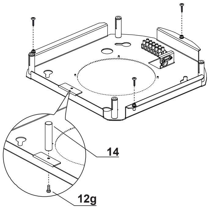
text_image
Technical diagram of a mechanical assembly with labeled parts and dimensions, including 12g and 14 measurements.natural_image
Diagram of a mechanical or laboratory setup with a cylindrical component and a base plate, showing internal components and motion lines (no text or symbols)
text_image
Safety warning diagram showing hand protection, warning symbol, and safety instructions for a device setup.flowchart
graph TD
    A["Step 1: Hexagonal nut"] --> B["Step 2: Hexagonal nut"]
    B --> C["Arrow 1 to top: ↑"]
    B --> D["Arrow 2 to bottom: ↓"]
natural_image
Technical line drawing of a mechanical component with mounting holes and mounting feet (no text or symbols)6
text_image
Technical diagram showing a mechanical assembly with labeled components and a magnified inset highlighting the 2X feature.
text_image
4X
natural_image
Technical line drawing of a mechanical component with mounting holes and mounting feet (no text or symbols)7
text_image
3/16" OK!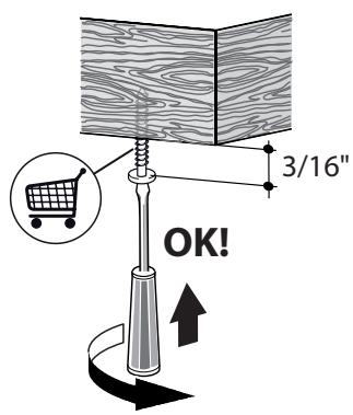
text_image
3/16" OK!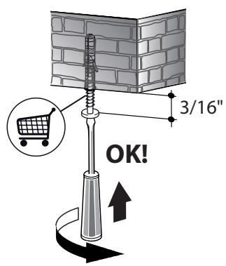
text_image
3/16" OK!natural_image
Pure diagram of a mechanical or electrical component with no text, numbers, or symbolsnatural_image
Illustration of two people installing or adjusting a large cylindrical device on an induction cooktop, with one person climbing and the other standing on a ladder (no text or symbols)
natural_image
Technical line drawing of a cylindrical device with internal components and wiring, no text or symbols present9

text_image
A B C 1510
text_image
14
natural_image
Line drawing of a hand holding a cable with two arrows pointing to a component, no text or symbols presentnatural_image
Technical line drawing of a cylindrical mechanical device with attached components and directional arrows indicating motion (no text or symbols)13
natural_image
Diagram of a mechanical device with a coiled spring and rotating cable, showing motion direction (no text or symbols)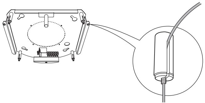
natural_image
Technical line drawing of a mechanical assembly with an inset showing a cable inserted into a component (no text or symbols present)MISE À NIVEAU DE LA HOTTE
natural_image
Technical line drawing of a cylindrical mechanical device with vertical supports and internal components, no text or symbols present.
text_image
13/16"
text_image
2 1
text_image
0.0°Branchements
natural_image
Technical diagram of a mechanical assembly with concentric circular components and mounting holes (no text or labels)natural_image
Illustration of a pair of medical or surgical devices with no visible text or symbolsPanneau de commande

natural_image
Illustration of a hand pressing a device with a finger, showing a curved arrow (no text or symbols)National Fire Protection Association
Batterymarch Park
Quincy, Massachusetts 02269
text_image
16 1/8" 16 15/16" Max. 51 5/8"
text_image
4 3/16" 4 3/16" Ø5 7/8" 4 3/16" 4 3/16"
text_image
Min. 24" Min. 30"INSTALACIÓN
natural_image
Illustration of a hand using a screwdriver to cut a screwdriver into a workpiece (no text or symbols present)natural_image
Technical line drawing of a mechanical component with mounting holes and support legs (no text or symbols)
natural_image
Technical line drawing of a circular mechanical component with concentric rings and mounting holes (no text or symbols)
text_image
Technical diagram of a mechanical assembly with labeled parts and dimensions, including 12g and 14 measurements.natural_image
Diagram of a mechanical or laboratory setup with a cylindrical component and a base plate, showing internal components and motion lines (no text or symbols)
text_image
Safety warning diagram showing hand protection, safety warning symbol, and electrical circuit setup with labeled componentsflowchart
graph TD
    A["Step 1: Hexagonal nut"] --> B["Step 2: Hexagonal nut"]
    B --> C["Arrow 1 to top: ↑"]
    B --> D["Arrow 2 to bottom: ↓"]

natural_image
Technical line drawing of a mechanical component with mounting holes and mounting feet (no text or symbols)6

text_image
2X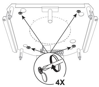
text_image
4X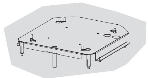
natural_image
Technical line drawing of a mechanical assembly with mounting holes and cylindrical components (no text or symbols)7

text_image
3/16" OK!
text_image
3/16" OK!
text_image
3/16" OK!natural_image
Pure diagram of a mechanical or electrical component with no text, numbers, or symbolsnatural_image
Illustration of two people installing or adjusting a large cylindrical device on an induction cooktop, with one person climbing and the other standing on a ladder (no text or symbols present)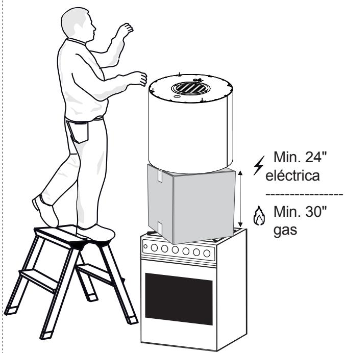
text_image
Min. 24" eléctrica Min. 30" gasnatural_image
Technical line drawing of a cylindrical industrial device with internal components and mounting base (no text or symbols)9
text_image
A B C 1510
text_image
14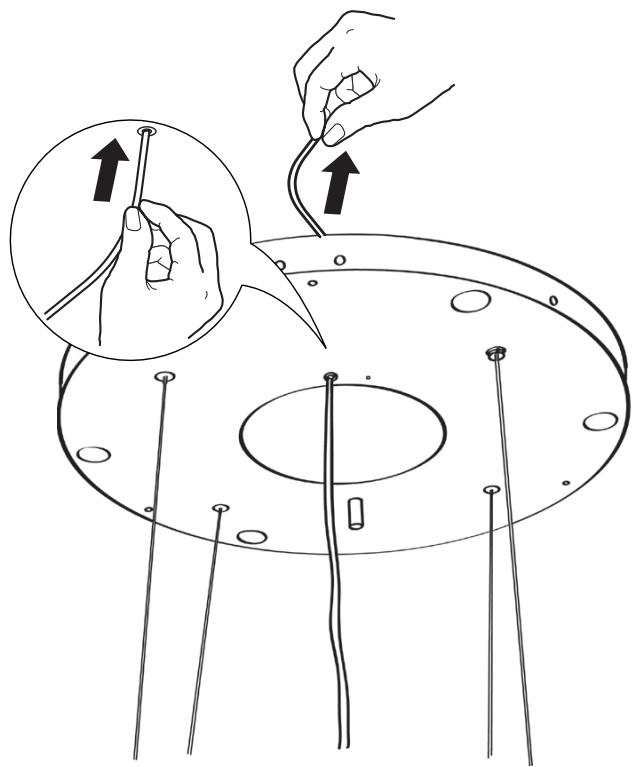
natural_image
Illustration of hands connecting wires to a circular component with pins, showing a magnified inset (no text or symbols)natural_image
Technical line drawing of a cylindrical mechanical device with vertical supports and internal components, showing upward force arrows (no text or symbols)13

natural_image
Diagram of a mechanical device with a coiled spring and rotating cable, showing motion direction (no text or symbols)
natural_image
Technical line drawing of a mechanical assembly with an inset showing a cable inserted into a component (no text or symbols present)NIVELANDO
LA CAMPANA
natural_image
Technical line drawing of a cylindrical mechanical device with vertical supports and internal components, no text or symbols present.
text_image
13/16"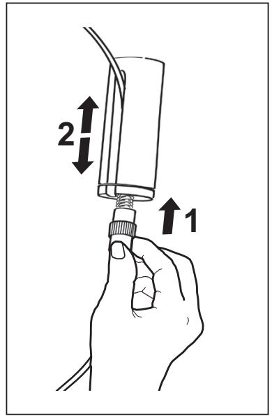
text_image
2 1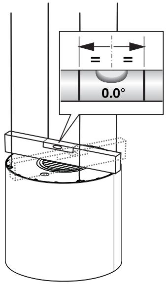
text_image
0.0°Conexiones
natural_image
Technical diagram of a mechanical assembly with concentric circular components and mounting holes (no text or labels)natural_image
Technical line drawing of a cylindrical device with internal components and wiring (no text or symbols)PANEL DE CONTROL
natural_image
Illustration of a pair of medical or surgical devices with no visible text or symbolsPanel de control

natural_image
Illustration of a hand pressing a device with a finger, showing a curved arrow (no text or symbols)flowchart
graph TD
    A["Power Supply"] --> B["FABER ATF"]
    B --> C["BLK"]
    C --> D["BLK"]
    D --> E["BLK"]
    E --> F["BLK"]
    F --> G["BLK"]
    G --> H["BLK"]
    H --> I["BLK"]
    I --> J["BLK"]
    J --> K["BLK"]
    K --> L["BLK"]
    L --> M["BLK"]
    M --> N["BLK"]
    N --> O["BLK"]
    O --> P["BLK"]
    P --> Q["BLK"]
    Q --> R["BLK"]
    R --> S["BLK"]
    S --> T["BLK"]
    T --> U["BLK"]
    U --> V["BLK"]
    V --> W["BLK"]
    W --> X["BLK"]
    X --> Y["BLK"]
    Y --> Z["BLK"]
    Z --> AA["BLK"]
    AA --> AB["BLK"]
    AB --> AC["BLK"]
    AC --> AD["BLK"]
    AD --> AE["BLK"]
    AE --> AF["BLK"]
    AF --> AG["BLK"]
    AG --> AH["BLK"]
    AH --> AI["BLK"]
    AI --> AJ["BLK"]
    AJ --> AK["BLK"]
    AK --> AL["BLK"]
    AL --> AM["BLK"]
    AM --> AN["BLK"]
    AN --> AO["BLK"]
    AO --> AP["BLK"]
    AP --> AQ["BLK"]
    AQ --> AR["BLK"]
    AR --> AS["BLK"]
    AS --> AT["BLK"]
    AT --> AU["BLK"]
    AU --> AV["BLK"]
    AV --> AW["BLK"]
    AW --> AX["BLK"]
    AX --> AY["BLK"]
    AY --> AZ["BLK"]
    AZ --> BA["BLK"]
    BA --> BB["BLK"]
    BB --> BC["BLK"]
    BC --> BD["BLK"]
    BD --> BE["BLK"]
    BE --> BF["BLK"]
    BF --> BG["BLK"]
    BG --> BH["BLK"]
    BH --> BI["BLK"]
    BI --> BJ["BLK"]
    BJ --> BK["BLK"]
    BK --> BL["BLK"]
    BL --> BM["BLK"]
    BM --> BN["BLK"]
    BN --> BO["BLK"]
    BO --> BP["BLK"]
    BP --> BQ["BLK"]
    BQ --> BR["BLK"]
    BR --> BS["BLK"]
    BS --> BT["BLK"]
    BT --> BU["BLK"]
    BU --> BV["BLK"]
    BV --> BW["BLK"]
    BW --> BX["BLK"]
    BX --> BY["BLK"]
    BY --> BZ["BLK"]
    BZ --> CA["BLK"]
    CA --> CB["BLK"]
    CB --> CC["BLK"]
    CC --> CD["BLK"]
    CD --> CE["BLK"]
    CE --> CF["BLK"]
    CF --> CG["BLK"]
    CG --> CH["BLK"]
    CH --> CI["BLK"]
    CI --> CJ["BLK"]