USER MANUAL PRIOS 35 ARISTON
USER AND INSTALLATION MANUAL

CLASSE A++

FUNZIONE ECO ECO FUNCTION
- PICCOLA MANUTENZIONE.. 11
3. PICCOLA MANUTENZIONE
ATTENZIONE:
This manual is intended for the air conditioning unit installers and end users. Failure to observe the indications contained in this manual shall void the warranty.
This manual constitutes an integral and essential part of the product. It must be stored with care by the user and should always be passed on to new owners or users of the appliance, and/or when the latter is transferred to another system.
In order to ensure correct and safe use of the appliance, both installer and user, each for his/her respective requirements, must read the instructions and precautions contained in this manual carefully, as they provide important safety indications concerning installation, use and maintenance of the appliance.
This manual is divided into two separate sections:
1. OPERATING AND MAINTENANCE INSTRUCTIONS
This section contains all the information required to operate the appliance correctly and to carry out regular checks and maintenance procedures on the appliance.
2. INSTALLATION
This section is intended for installers. It contains all the indications and instructions that professionally qualified personnel must observe in order to ensure optimal installation of the appliance.
The manufacturer reserves the right to modify the data and contents of this manual without prior notice, with the aim of improving the quality of the relative products.
In order to make the content - provided in several languages and applicable to various countries - easier to understand, all illustrations can be found towards the end of the manual and apply to all languages.
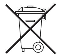
The barred dustbin symbol appearing on the device indicates that the product must be disposed of separately from household waste once it reaches the end of its lifespan, and transferred to a waste disposal site for electric and electronic equipment, or returned to the dealer when purchasing a new device of the same kind.
The user is responsible for delivering the decommissioned device to a suitable waste disposal site.
Proper separated collection of the decommissioned device and its subsequent eco-compatible recycling, treatment and disposal helps to prevent negative effects on the environment and health, besides encouraging the reuse of the materials comprising the product.
For further details on the available waste collection systems, contact your local waste disposal office, or the dealer from which the product was purchased.
m = 311 ;
TABLE OF CONTENTS:
OPERATING AND MAINTENANCE INSTRUCTIONS
SAFETY STANDARDS.. page 29
- WALL-HUNG MODEL.. page 31
1.1 Internal unit panel
1.2 Display.. page 32
- OPERATION page 33
2.1 Basic functions
2.2 Special functions.. page 34
2.3 Air treatment filters
- SIMPLE MAINTENANCE page 35
3.1 Cleaning the filters
3.2 Cleaning the air conditioning unit
4.END OF SEASON MAINTENANCE page 36
4.1 If the air conditioning unit does not work
INSTALLATION
INSTALLATION ACCESSORIES.. page 37
SAFETY STANDARDS.. page 38
- INSTALLATION.. page 39
1.1 Minimum distances
1.2 Installing the template
1.3 Installing the internal unit.. page 41
1.4 Installing the external unit
- PILING AND CONNECTIONS.. page 42
2.1 Connecting the refrigeration piping
2.2 Draining the condensation from the internal unit
2.3 Draining the condensation from the external unit
2.4 Tools.. page 43
2.5 Thickness of the copper pipes
2.6 How to connect the pipes
2.7 Connections to the internal unit
2.8 Connections to the external unit.. page 44
2.9 Creating a vacuum and checking the seal
2.10 Recovering the refrigerant.. page 46
2.11 Charging the refrigerant gas
- ELECTRICAL CONNECTIONS.. page 47
3.1 Connecting the internal unit
3.2 Connecting the external unit
3.3 Connecting to the mains electricity supply.. page 48
3.4 Connection types
- FINAL STAGES . page 49
4.1 Testing
DIMENSIONS.. page 147
WIRING DIAGRAMS 151
LEGEND 155
INTERNAL AND EXTERNAL UNIT LABEL page 158
OPERATING AND MAINTENANCE INSTRUCTIONS
SAFETY STANDARDS
READ THIS MANUAL THOROUGHLY AND KEEP IT IN A SAFE PLACE, AS IT CONTAINS IMPORTANT INFORMATION FOR THE SAFE INSTALLATION, USE AND MAINTENANCE OF YOUR NEW APPLIANCE.
| STANDARD | RISK | |
| Do not perform any operations that involve opening the appliance. | Electrocution due to exposure to live components.
Personal injury caused by burns due to overheated components, or wounds caused by sharp edges or protrusions. | A |
| Do not perform operations that involve removing the device from its housing. | Electrocution due to exposure to live components.
Personal injury from burns due to cooling gases leaking from disconnected piping. According to relevant standards, the font size must be at least 3 mm for capital letters. | A |
| Do not start or stop the appliance simply by plugging it into the electricity mains supply or unplugging it. | Electrocution through contact with a damaged cable or plug, or socket. | A |
| Do not wrap/damage/modify/heat the power supply cable, or stand heavy objects on top of it. | Electrocution from non-insulated live wires. | A |
| Do not leave anything on top of the appliance. | Personal injury from an object falling off the appliance following vibrations. | A |
| Do not climb onto the appliance. | Personal injury due to the appliance falling. | A |
| Do not climb onto chairs, stools, ladders or unstable supports to clean the device. | Personal injury caused by falling from a height or shearing (stepladders shutting accidentally). | A |
| Do not attempt to clean the appliance without first turning it off and unplugging it or switching the dedicated switch off. | Electrocution due to exposure to live components. | A |
| This appliance can be used by children over 8 years of age or by inexperienced persons under supervision, provided that they have been suitably instructed in safe appliance operation and warned about the potential risks connected with it. | Damage to the device caused by improper use.
Personal injury. | A |
| This appliance can be used under supervision by persons with limited physical, mental or sensory abilities, provided that they have been suitably instructed in safe appliance operation and warned about the potential risks connected with it. | Damage to the device caused by improper use.
Personal injury. | A |
| Do not direct the air flow towards gas hobs or gas stoves. | Explosions, fires or intoxication from the discharge of gas from supply nozzles. Flames extinguished by the air flow. | A |
| Do not place your fingers in the air outlets or in the air inlet grilles. | Electrocution due to exposure to live components.
Personal injury from cuts. | A |
| Do not drink the condensation water. | Personal injury from poisoning. | A |
| If you smell burning or see smoke coming out of the device, disconnect it from the power supply, open all windows and contact the technician. | Personal injury from burns or smoke inhalation. | A |
| Children must not play with the appliance. | Damage to the device caused by improper use.
Personal injury. | A |
| Cleaning and maintenance must not be carried out by children without supervision. | Damage to the device caused by improper use.
Personal injury. | A |
| Do not perform operations that involve removing the device from its housing. | Flooding caused by water leaking from disconnected piping. | A |
| Do not leave anything on top of the appliance. | Damage to the appliance or any underlying objects caused by the appliance coming loose from its fixing brackets and falling. | ▲ |
| If the power supply cable is damaged, it must be replaced by the manufacturer or by its technical assistance service, or at least by a suitably qualified individual, in order to prevent all hazards. | Personal injury due to electrocution. | ▲ |
| Do not operate the unit in the presence of hazardous substances or flammable/corrosive gases. | Risk of fire, injury, explosion. | ▲ |
| Do not use insecticides, solvents or aggressive detergents to clean the device. | Damage to plastic or painted parts. | ▲ |
| Do not use the appliance for any purpose other than normal domestic use. | Damage to the device caused by operation overload. Damage to objects caused by improper use. | ▲ |
| Do not direct the air flow towards valuable items, plants or animals. | Damage or perishing due to excessive cold/heat, humidity, ventilation. | ▲ |
| Do not use the air conditioning unit for extended periods of time in conditions where the humidity level is over 80%. | Damage to objects due to excessive dripping of condensation from the appliance. | ▲ |
| Do not position other electrical appliances, furniture or humidity-sensitive items directly underneath the internal or external unit. | Condensation water may drip and cause damage or malfunctioning. | ▲ |
| Provide sufficient ventilation in the room in which the air conditioning unit is installed if a combustion appliance is also located there. | Lack of oxygen. | ▲ |
| Avoid prolonged exposure to the air flow. | Health issues. | ▲ |
| Make sure the external unit frame and supporting structure are intact at least once every 12 months. | Personal injury caused by objects falling from a height, damage to the product. | ▲ |
Symbol legend:
Failure to comply with this warning implies the risk of injury to persons, which in some circumstances may be fatal.
Failure to comply with this warning implies the risk of damage, in some circumstances serious, to property, plants or animals.
1. WALL-HUNG MODEL
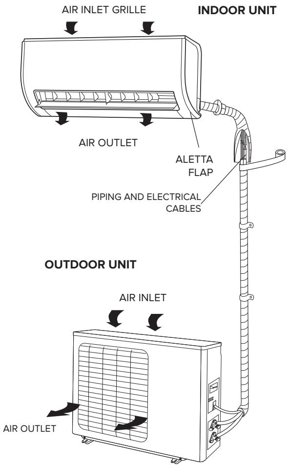
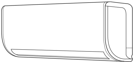
The air conditioning unit consists of two (or more) units connected to one another by (suitably insulated) piping and an electrical power supply cable. The Internal Unit should be installed on a wall of the room to be air conditioned. The External Unit can be free standing on the floor or fitted to a wall, on special supporting brackets.
In the case of monosplit type installation, the external unit has a single connection to the internal unit, while in a multi-split installation several internal units are connected to a single external unit.
Operating recommendations:
- For the air conditioning unit to work at its best, make sure it is suitably sized for your specific air conditioning requirements (risk of poor appliance performance).
- Do not obstruct the air inlet and outlet grilles with any objects (risk of the appliance overheating).
- If the appliance is left unused for an extended period of time, disconnect the power supply cable from the mains as the appliance would otherwise remain powered (risk of personal injury from fire and fumes).
- For optimal appliance performance, keep the room temperature uniform using the swing function, close doors and windows and clean the filters regularly.
- Do not cool the room excessively, to prevent sudden changes in temperature.
WARNING:
- Do not start or stop the appliance by simply plugging it into or out of the electricity mains (risk of personal injury due to electrocution).
- Do not climb onto the internal or external unit and do not place any objects on them at all (risk of personal injury and damage to any objects that fall from a height).
- Avoid prolonged direct exposure to the air flow (risk of personal injury due to sensitisation of the skin).
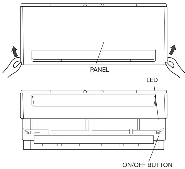
1.1 Internal unit panel
Press this button to switch the unit on/off. The operating mode is AUTO (Tset=24°C).
If the on/off button is pressed twice in succession, the air conditioning unit enters forced cooling mode (used exclusively by the installer during the testing phase).
WARNING:
- Do not operate the switch with wet hands (risk of personal injury from electrocution).
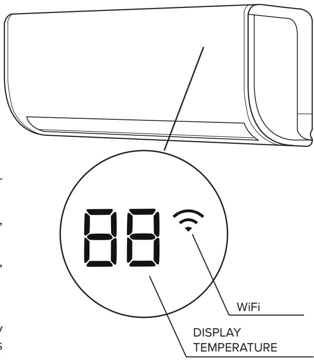
1.2 Smart Display
The air conditioning unit has a display which enables viewing of the operating parameters (see figure).
. 88 Led
- ON Indicates the temperature set in normal operating conditions.
- OF displayed for 3 seconds on activation of TIMER, SWING, TURBO or SILENCE.
- DF displayed for 3 seconds on deactivation of TIMER, SWING, TURBO or SILENCE.
- SC is displayed during SELF CLEAN operation.
- EF is displayed during preheating of the refrigerant, by regulating the fan on the internal unit, until the gas reaches 23^ C . This operation is used to avoid blowing cold air into the room in the first few seconds of operation.
- CL is displayed for 15 seconds when the air conditioning unit reaches 240 hours of operation, to indicate the need to clean the air filters. At each new start-up, the message is repeated until the internal counter is manually reset by pressing the LED button on the remote control 4 times. This operation can be carried out only during the 15 seconds in which the message is displayed.
- NF is displayed for 15 seconds when the air conditioning unit reaches 2880 hours of operation, to indicate the need to replace the special filters. At each new start-up, the message is repeated until the internal counter is manually reset by pressing the LED button on the remote control 4 times. This operation can be carried out only during the 15 seconds in which the message is displayed.
- R P is displayed when the air conditioning unit is in Access Point mode, for configuring the Wi-Fi module.
- FP appears during antifreeze mode
- ECO appears sequentially E-C-D and 2 times the setting temperature, it means the "ECO" function is activated.
- WiFi can be observed when Wi-Fi function is operating and the air conditioner is connected to the household internet wireless. (only with Wi-Fi kit, to be purchased separately)
2. OPERATION
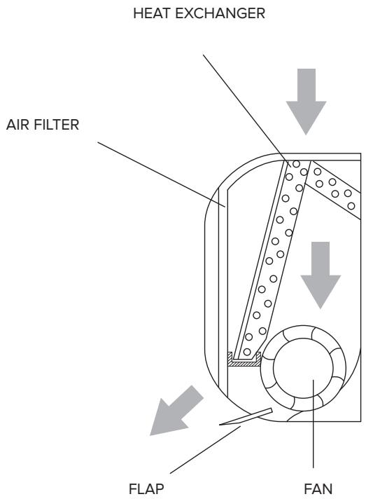
The air conditioning unit is an appliance designed to create the ideal climatic conditions for the well-being of people in a room. It cools, dehumidifies and heats air completely automatically.
The air sucked in by the fan enters via the grille at the top and then passes through the filter that traps any dust it may contain. It is then conveyed through the fins of a "heat exchanger": namely a finned coil that cools the air and dehumidifies it, or even heats it. The heat removed from (or transferred to) the room is vented (or drawn in from) outside via the external unit.
The fan circulates the air around the room: the direction in which the air exits the unit is adjusted vertically by the flap and horizontally by the automatic louver deflectors.
2.1 Basic functions
HEATING
In this mode, the air conditioning unit heats the room by means of "heat pump" operation.
COOLING
In this mode, the air conditioning unit cools down the room while at the same time reducing the humidity in the air.
This mode circulates air throughout the room.
This mode, with its alternating cooling and ventilation cycles, is designed to achieve air dehumidification without significantly altering the room temperature.
Fan mode and speed are set automatically based on the room temperature detected.
TURBO
This function allows the unit to reach the set temperature in the shortest possible time.
This function allows you to turn the air conditioning unit on or off at the desired time.
VERTICAL SWING
This function enables automatic oscillation of the flap.
2.2 Special functions
This function adjusts the temperature automatically in order to make the room more comfortable at night.
FOLLOW-ME FUNCTION
Air conditioning unit operation depends on the remote control sensor, which detects the current temperature of the room in which it is located.
SELF CLEAN (monosplit installations only)
In self clean mode the air conditioning unit automatically cleans and dries the evaporator, keeping it in optimal conditions for subsequent operation.
HORIZONTAL SWING
This function enables automatic oscillation of the internal horizontal louvers.
LOW AMBIENT
This function allows the air conditioning unit to operate in cooling mode when outdoor temperatures fall below 15^ .
- REFRIGERANT LEAK SENSOR (cooling mode only) (monosplit installations only)
The air conditioning unit identifies any refrigerant leaks and shows "EC" on the display (the RUN and TIMER LEDs flash on an LED display).
This function allows the air conditioning unit, in the event of a powercut, to restart with the last function set once the power supply has been restored (mode, temperature, fan speed and flap position).
- SILENCE (monosplit installations only)
This function allows the air conditioning unit to set an ultra-low fan speed for the internal unit, to keep the room extremely silent.
Used to save the current settings or restore previous settings.
This function can be used to switch off the internal unit display.
12-SPEED FAN
For each of the 3 speed settings (HIGH, MED. LOW), the air conditioning unit has three speed sub-levels (HIGH, HIGH+, HIGH-, MED, MED+, MED-, LOW, LOW+, LOW-) which are set automatically. These 9 sub-levels, together with the dehumidification, turbo and silence function speeds, mean the air conditioning unit offers 12 air flow speeds in total.
When it is switched off, the air conditioning unit memorises the last flap position set.
- ECO FUNCTION (monosplit installations only)
This function, available only in cooling mode, minimises electricity consumption by optimising the compressor's operating parameters and the speed of the fans on the internal and external units, as the ambient temperature changes
- BOOSTER (monosplit installations only)
This function reduces the time required to reach the set temperature
SELF CLEAN (monosplit installations only)
This function inverts the rotation direction of the external unit fan, directing the air flow onto the external exchanger, cleaning it of impurities to ensure a long life for the product. It is activated at every shutdown and during SELF CLEAN.
Wi-Fi
This function, through a dedicated application, can be used to control the air conditioning unit with a mobile device (smartphone/tablet), from inside the home or away from the home.
2.3 Air treatment filters
Porous filter used in conjunction with essential oils (not supplied with the product) for fragrance diffusion.
Removes bacteria and mould and prevents the causes of common allergies by capturing allergens in the air and breaking them down
3. SIMPLE MAINTENANCE
WARNING:
- Unplug the appliance or switch off the dedicated switch before performing any operations (risk of personal injury from electrocution).
- Do not touch the air conditioning unit with wet hands (risk of personal injury from electrocution).
- When cleaning the appliance, do not climb onto a table or unstable chair (risk of personal injury due to falling from a height).
- When removing filters, take care not to touch any metal parts, especially the heat exchanger inside the internal unit (risk of personal injury from cuts).
3.1 Cleaning the filters
Cleaning the filters regularly is essential for optimal performance of the air conditioning unit. For domestic settings, we recommend that filters be cleaned fortnightly. The need to clean the air filters or replace the special filters is however indicated on the display, on the basis of the hours that the air conditioning unit has operated.
Dust filters
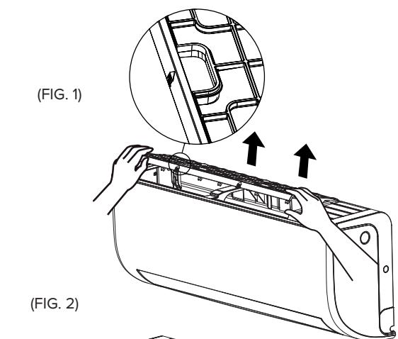
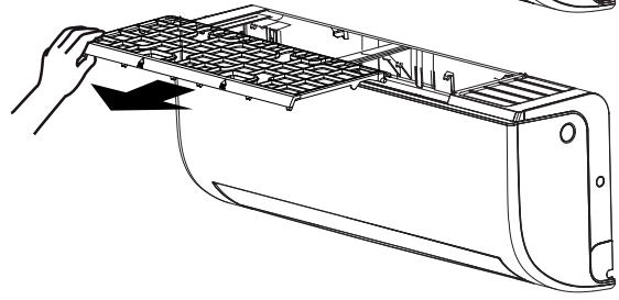
By pulling upwards carefully unfasten the filter on the top of the internal unit (fig. 1). Then remove it by pulling towards you (fig. 2). Clean them using a vacuum cleaner or wash them in lukewarm water and neutral detergent. Make sure you dry them thoroughly before replacing them. Do not leave them exposed to sunlight. Do not operate the air conditioning unit without the air filters.
Air treatment filters
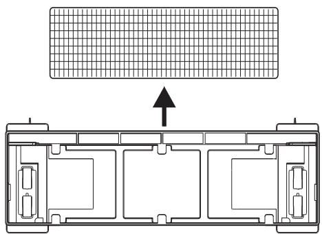
Open the front panel and remove the dust filters as described above. Remove the air treatment filters from their seat as illustrated in fig. 3.
These filters must be replaced once they are no longer capable of performing their task (approx. 24 months).
The filter uses the air flow passing through the air conditioning unit to diffuse the desired fragrance within the room. To add the fragrance, remove the filter as described above; pour the desired amount of scent onto each end of the filter and at its centre; position the filter back in its seat.
The ideal amount of scent depends on the type of fragrance used and individual user preferences: we recommend starting with small amounts (e.g. 5 ml).
Note: use essential oils specifically designed as room fragrances.
3.2 Cleaning the air conditioning unit
Clean the Internal Unit and remote control, if necessary, using a cloth moistened with lukewarm water (no hotter than 40^ ) and mild soap; do not use solvents or aggressive detergents, insecticides or spray cleaners (risk of damaging or corroding the plastic parts of the appliance).
Take extra care when cleaning the front panel, as it is very easy to scratch.
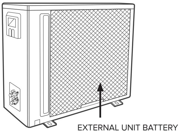
If the External Unit battery is clogged up, remove all leaves and deposits and then wash off all dust with a water jet or some water.
(FIG. 3)
FILTERS
4. END OF SEASON MAINTENANCE
WARNING:
- Unplug the appliance or switch off the dedicated switch before performing any operations (risk of personal injury from electrocution).
- Do not touch the air conditioning unit with wet hands (risk of personal injury from electrocution).
- When cleaning the appliance, do not climb onto a table or unstable chair (risk of personal injury due to falling from a height).
-
When removing filters, take care not to touch any metal parts, especially the heat exchanger inside the internal unit (risk of personal injury from cuts).
-
Clean the filters and secure them back in place.
- On a sunny day, run the air conditioning unit in ventilation mode for a few hours, so that the inside is completely dry.
- Unplug the appliance or disable the automatic switch.
4.1 If the air conditioning unit does not work
-
If the appliance shows no signs of life, make sure that:
-
power is being supplied from the mains
- the automatic switch has not blown
- the power supply has not been cut off
-
the air conditioning unit comes on when the ON-OFF button on the internal unit is pressed
-
If the cooling (or heating) effect seems to be lower than normal:
-
has the temperature been set correctly on the remote control?
- has a door or window been opened?
- is the Internal Unit exposed to direct sunlight?
- are the filters clogged?
- are there any obstacles preventing the free circulation of air to the Internal Unit or External Unit?
The performance levels and the characteristics of any cooling appliance are noticeably affected by the environmental conditions where the Internal and External Units operate.
| Cooling | outdoor temperature between -15° and 50°C |
| Heating | outdoor temperature between -15° and 30°C |
WARNING:
The relative humidity in the room must be lower than 80% . If the air conditioning unit operates above this limit, condensation may form on its surface and begin to drip.
INSTALLATION
MONOSPLIT 2,5 - 3,5 - 5 - 7 kW / MULTISPLIT 5,5 - 8 - 11 - 12,1 kW
Installation accessories
| Name and Description | Qty. | Operation |
| Template for the internal unit | 1 | To install the internal unit |
| Screws + Rawlplugs | 5 | |
| Condensation discharge pipette with seal | 1 | To empty the external unit of condensation |
| Batteries | 2 | For the remote control |
| Remote control with support | 1+1 | |
| Air treatment filter | 2 | |
| Transition fitting 3/8” - 1/2” | 1 | Only PENTA 121
XD0C-O |
Internal unit - external unit compatibility
Each internal unit can be connected to an external unit as specified in the table below.
| INSTALLATION TYPE | EXTERNAL UNIT | INTERNAL UNIT | SET |
| MONOSPLIT | NEVIS PLUS 25 MD0-O | NEVIS PLUS 25 UDO-I | NEVIS PLUS 25 MUDO |
| NEVIS PLUS 35 MD0-O | NEVIS PLUS 35 UDO-I | NEVIS PLUS 35 MUDO |
| NEVIS PLUS 50 MD0-O | NEVIS PLUS 50 UDO-I | NEVIS PLUS 50 MUDO |
| MULTISPLIT | DUAL 50 XDOC-O | NEVIS PLUS 25 UDO-I | --- |
| TRIAL 80 XDOC-O | NEVIS PLUS 35 UDO-I |
| QUAD 110 XDOC-O | NEVIS PLUS 50 UDO-I |
| PENTA 121 XDOC-O |
SAFETY STANDARDS
READ THIS MANUAL THOROUGHLY AND KEEP IT IN A SAFE PLACE, AS IT CONTAINS IMPORTANT INFORMATION FOR THE SAFE INSTALLATION, USE AND MAINTENANCE OF YOUR NEW APPLIANCE.
| STANDARD | RISK | |
| Make sure the installation site and any systems to which the device must be connected comply with the applicable regulations. | Electrocution caused by contact with live wires that have been incorrectly installed. | A |
| When drilling the wall, take care not to damage any electrical wiring or existing piping. | Electrocution caused by exposure to live wires. Explosions, fire or intoxication due to gas leaks from damaged pipes. | A |
| Protect connection piping and cables so as to prevent damage to them. | Electrocution caused by exposure to live wires. Cold burns due to gas leaking from damaged piping. | A |
| Use suitable manual tools and equipment (make sure in particular that the tool is not worn out and that its handle is fixed properly); use them correctly and make sure they do not fall from a height. Replace them once you have finished using them. | Personal injury from falling splinters or fragments, inhalation of dust, shocks, cuts, pricks and abrasions. | A |
| Use electrical equipment suitable for the intended use (in particular, make sure that the power supply cable and plug are intact and that the parts featuring rotary or reciprocating motion are fastened correctly); use this equipment correctly; make sure no equipment could fall from a height. Disconnect it and put it safely back in place after use. | Personal injury from electrocution, flying splinters or fragments, inhalation of dust, shocks, cuts, pricks, abrasions, noise and vibration. | A |
| Make sure that any portable ladders are securely positioned, that they are strong enough, that the steps are intact and not slippery, that the ladders are not moved with someone on them and that someone supervises at all times. | Personal injury caused by falling from a height or shearing (stepladders shutting accidentally). | A |
| Make sure that any rolling ladders are positioned securely, that they are suitably sturdy, that the steps are intact and not slippery. Make sure that the ladders are fitted with handrails on either side of the ladder and parapets on the landing. | Personal injury caused by falling from a height. | A |
| During all work carried out off the floor (generally at a height over two metres or 6 feet), make sure that parapets are used to surround the work area or individual harnesses designed to prevent falls worn, that the space covered during any accidental fall is free from dangerous obstacles, and that any impact upon falling is cushioned by semi-rigid or deformable surfaces. | Personal injury due to impact, tripping and wounds. | A |
| During all work procedures, wear individual protective clothing and equipment. | Personal injury caused by electrocution, flying splinters or fragments, inhalation of dust, shocks, cuts, puncture wounds, abrasions, noise and vibration. | A |
| All operations inside the device must be performed with the necessary caution in order to avoid sudden contact with sharp parts. | Personal injury from cuts, pricks and abrasions. | A |
| Recharge the refrigerant gas in accordance with the instructions provided on the product safety data sheet, while wearing protective clothing and avoiding sharp bursts of gas from the tank or from the system connections. | Personal injury from cold burns. | A |
| Do not direct the air flow towards gas hobs or gas stoves. | Explosions, fires or intoxication from the discharge of gas leaking from the burner nozzle once the air flow has put the flame out. | A |
| Do not install the external unit in places where it could constitute a risk or an obstruction to passers-by, or where it could disturb people due to the noise it makes, the heat produced or the air flow. | Personal injury from contusions, stumbling, noise and excessive ventilation. | A |
| Install the appliance in a site which complies with its IP rating, in line with current standards. | Damage to the appliance, injury. | A |
| When lifting loads with a crane or hoist, make sure the equipment used for lifting is stable and efficient and suitably sized for the movement and weight of the load itself; place the load correctly in slings, tie ropes around it to limit any oscillations and lateral movements; lift the load from a position where there is a full view of all the space covered by the load during lifting; do not allow people to pass or stop in the vicinity of the suspended load. | Personal injury due to objects falling from a height. Damage to the appliance or surrounding objects due to the appliance falling from a height, knocks. | △ |
| Do not direct the air flow towards valuable items, plants or animals. | Damage or perishing due to excessive cold/heat, humidity, ventilation. | △ |
| Install the device on a solid wall that is not subject to vibrations. | Noise during operation. | △ |
| Place the condensation drainpipe in such a way as to ensure the correct flow of water towards places where it cannot disturb or injure people or animals, or damage possessions. | Damage to objects due to dripping water. | △ |
| Perform all electrical connections using suitably-sized conductors. | Fire caused by overheating due to electrical current passing through undersized cables. | △ |
| Use electrical equipment suitable for the intended use (in particular, make sure that the power supply cable and plug are intact and that the parts featuring rotary or reciprocating motion are fastened correctly); use this equipment correctly; make sure no equipment could fall from a height. Disconnect it and put it safely back in place after use. | Damage to the appliance or surrounding objects from falling splinters, knocks and incisions. | △ |
| Protect the appliance and all areas in the vicinity of the work site using suitable material. | Damage to the device or surrounding objects caused by flying splinters, knocks and incisions. | △ |
| Move the appliance with the necessary care. | Damage to the device or surrounding objects caused by shocks, knocks, incisions and crushing. | △ |
| Organise the dislocation of all debris and equipment in such a way as to make movement easy and safe, avoiding any piles that could give way or collapse. | Damage to the device or surrounding objects caused by shocks, knocks, incisions and crushing. | △ |
| Reset all safety and control functions affected by any work performed on the appliance and make sure that they operate correctly before re-starting it. | Damage or shutdown of the device caused by out-of-control operation. | △ |
| The appliance must be installed in full compliance with national system regulations. | Personal injury. | △ |
| If the power supply cable is damaged, it must be replaced by the manufacturer or by its technical assistance service, or at least by a suitably qualified individual, in order to prevent all hazards. | Personal injury due to electrocution. | △ |
| Installation should be performed by an individual in possession of all necessary qualifications as required by law. | Personal injury. | △ |
| During the installation process, the refrigeration system should be connected first, followed by the electricity supply. In the event of replacement, proceed in the reverse order. | Personal injury due to electrocution or cold burns, injury from shocks, cuts or abrasions. | △ |
| The air conditioning unit must be fully earthed to prevent electric shocks. Do not connect the earth wire to lightning conductors, water or gas piping or telephone system earth wires. | Personal injury due to electrocution. | △ |
| Do not install the air conditioning unit near sources of heat or flammable material. | Personal injury, fire hazard. | △ |
Symbol legend:
Failure to comply with this warning implies the risk of injury to persons, which in some circumstances may be fatal.
Failure to comply with this warning implies the risk of damage, in some circumstances serious, to property, plants or animals.
1. INSTALLATION
11.1 Installation area
Make sure the installation site and any systems to which the appliance must be connected comply with applicable regulations. The interior unit should be installed in an appropriate area with the following conditions:
Good air circulation;
- Suitable drainage;
- The noise from the interior unit should not disturb other people;
- Rigid and stable structure: the area should not be subject to vibrations;
- The structure should be able to withstand the weight of the unit;
- Observe a distance of at least 1 metre from any electrical appliances (e.g. TV, radio, computer)
The unit should NOT be installed in the following places:
- near any source of heat, steam or combustible gas;
- near any flammable objects such as curtains or clothes;
- near obstacles that could obstruct the air flow;
- in a room subject to direct sunlight.
The appliance should be installed in a well ventilated area in which the dimensions of the room are compliant with the surface area.
FOR MODELS WITH REFRIGERANT R32:
- The appliance should be installed in a room with a surface area larger than 4m^2
- The appliance cannot be installed in a room with no ventilation if the surface area is less than 4m^2
1.2 Minimum distances
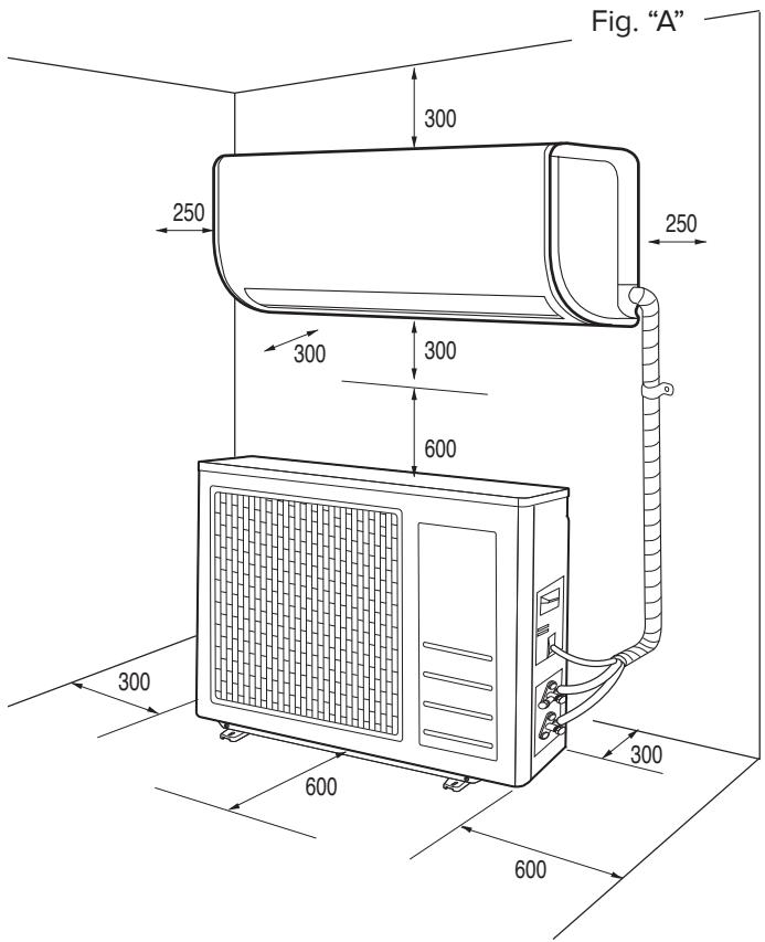
To ensure the appliance is installed correctly, keep to the minimum distances indicated in figure "A" and leave enough room for air to circulate freely. Use the accessories provided with the appliance to carry out the installation properly.
NOTES:
The dimensions of the internal and external units are given at the back of the manual.
WARNING:
- Use manual tools and equipment that are suitable for the intended purpose.
- When lifting loads with a crane or hoist, make sure the equipment used for lifting is stable and efficient and suitably sized for the movement and weight of the load itself; place the load correctly in slings, tie ropes around it to limit any oscillations and lateral movements; lift the load from a position where there is a full view of all the space covered by the load during lifting; do not allow people to pass or stop in the vicinity of the suspended load.
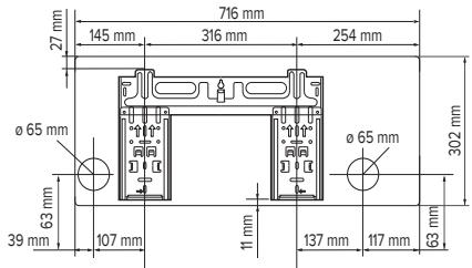
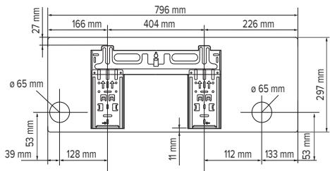
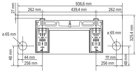
1.3 Installing the template
NOTES:
Install the internal unit in a place free from all obstacles (such as curtains) that could hinder the receipt of the remote control signals and that allows for the air filters to be pulled out without causing any inconvenience. Install the internal unit in a position where the air flow will not be obstructed.
WARNING:
Install the template on a solid wall that is not subjected to any vibrations.
- Using a mason's level, position the template in such a way as to ensure it is perfectly on-axis, both vertically and horizontally.
- Fasten the template with 5 screws. Be careful not to pierce or damage any pipes or wiring in conduits (risk of personal injury from electrocution).
- Then use the other screws to fasten the template to the wall uniformly across the entire surface.
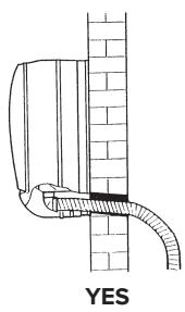
- Make a hole in the wall for all piping and electrical connections to pass through.
NOTE:
Refer to the dimensions of the template (see photo) to define the optimum position for the holes. The holes should have a diameter of at least 65~mm .
- Drill a hole in the wall that is 5 - 10mm lower on the outside than it is on the inside, so that the slope encourages downward flow of the condensation.
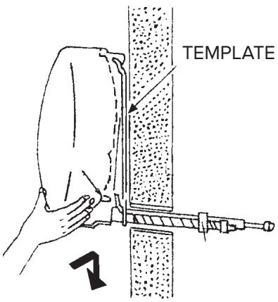
1.4 Installing the internal unit
- Push the piping, together with all cables, through the hole made in the wall and hook the internal unit onto the top of the template.
- Shape the piping and cables well.
- Push the lower part of the internal unit well up against the template.
NOTE:
Keep in mind the fact that the hooks on the template are smaller than the cavities at the rear of the unit. This allows you to adjust the position of the unit, with the template already secured to the wall, by approximately 30-50 mm to the left or right, according to the model.
Make sure that:
a. The top and bottom hooks on the internal unit are securely fastened onto the template.
b. The unit is fully horizontal.
If the appliance is not level, water may leak from it onto the floor.
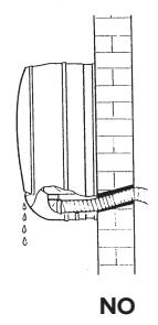
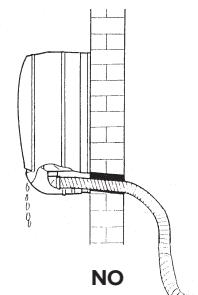
c. The drain pipe is at the right gradient (minimum of 3 cm for each metre in length).
d. The drain pipe stays at the bottom of the hole in the wall.
1.5 Installing the external unit
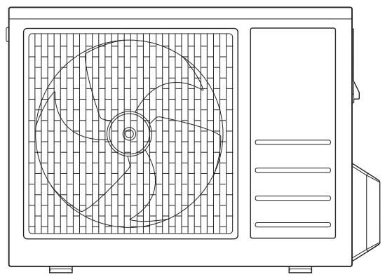
The external unit must be moved and stored in an upright position, to ensure suitable distribution of the oil in the refrigerant circuit and prevent damage to the compressor.
Adhere to the procedure as described, and then start connecting the piping and electrical wiring.
- Install the external unit in a place where the noise made by the appliance and the expelled hot air cannot be a source of inconvenience.
- Choose a place that does not obstruct free passage and where the condensation water produced can easily be ducted to the outside.
- Do not install the external unit in narrow areas which limit the air flow, or in places exposed to strong winds.
For wall installation:
- install the unit securely onto a solid wall;
- pinpoint the most suitable position on the wall, allowing enough room for any maintenance work to be carried out easily;
- fasten the brackets to the wall using rawlplugs suitable for the type of wall in question (take care not to damage any wiring or piping in conduits);
- use rawplugs which can support a weight greater than that of the external unit: during operation the machine vibrates and should remain installed for years without the screws becoming loose.
2. PILING AND CONNECTIONS
WARNING:
- Do not drink the condensation water (personal injury from poisoning).
- Position the condensation drain pipe in such a way as to allow for the correct downward flow of water in dedicated areas, and to prevent any inconvenience or damage to people, things, animals, plants and structures.
- Use manual tools and equipment that are suitable for the intended purpose.
2.1 Connecting the refrigeration piping
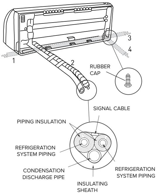
The piping can be positioned in different directions as indicated by numbers 1, 2, 3, 4 in the adjacent figure. In case of configuration "1","3" remove plastic cover. Turn the pipes in the direction of the hole in the wall, taking care not to constrict them in any way, and tape the refrigeration system piping, condensation drain pipe and electrical wiring together with electric (insulating) tape, keeping the condensation drain pipe at the bottom so that the water can flow freely.
2.2 Draining the condensation from the internal unit
The proper draining of condensation from the internal unit is fundamental for a good installation.
- Keep the condensation drain pipe (diameter 16,5 mm) at the bottom of the hole in the wall.
- Make sure the condensation drain pipe has a continuous gradient of approximately 3 cm per metre.
- Do not include any traps in the condensation discharge piping.
- Do not immerse the free end of the condensation drain pipe in water and do not leave it in the vicinity of places emanating unpleasant odours.
- When the installation is complete, before switching on the appliance, make sure the condensation drain pipe works properly by pouring some water into the condensation drip water tray situated inside the internal unit.
NOTE: The condensation drain tube is pre-installed on the same side as the refrigeration pipes. The internal unit, however, has a further housing, sealed by a rubber plug, on the opposite side to the refrigeration pipes. It is, therefore, possible to swap the positions of the drain tube and the rubber plug, making sure that the plug is correctly fitted to avoid water leakage
2.3 Draining the condensation from the external unit
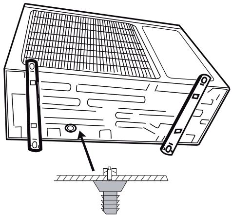
The condensation or water that forms in the external unit during operation in heating mode can be removed via the drain pipe fitting. Installation: fasten the drain pipe fitting (diameter 16mm ) to the hole on the bottom of the unit, as illustrated in the adjacent diagram. Connect the condensation drain pipe to the drain pipe fitting and ensure the other end of the pipe is ducted into a suitable drain.
2,5 kW 3,5 kW
WARNING:
- Only use piping specifically designed for ACR air conditioning units.
- Protect all connection cables and pipes in order to prevent their being damaged.
- Never use pipes with a thickness of under 0.8 mm .
- The appliance must be installed in full compliance with national system regulations.
- During the installation process, the refrigeration system should be connected first, followed by the electricity supply. In the event of replacement, proceed in the reverse order.
| TOOLS |
| A pressure gauge assembly |
| B pipe cutter |
| C recharge pipe |
| D electronic scale for refrigerant recharge |
| E dynamometric spanner |
| F clamp-shaped pipe vice |
| G xx mm hex key |
| H refrigerant canister |
| I vacuum pump |
| L HFC refrigerant leak detector |
2.5 Thickness of the copper pipes
| NOMINAL DIAMETER
(inches) | EXTERNAL DIAMETER
(mm) | THICKNESS
(mm) |
| 1/4 | 6.35 | 0.8 |
| 3/8 | 9.52 | 0.8 |
| 1/2 | 12.70 | 0.8 |
| 5/8 | 15.88 | 1.0 |
Split type air conditioning units operating with R410A refrigerant use a three-way external unit valve with a pin valve.
2.6 How to connect the pipes
- Only remove the pipe caps immediately prior to connection: under no circumstances must you let dampness or dirt enter.
- If a pipe is bent too many times, it becomes hard: do not bend it more than 3 times in the same section. Unwind the pipe by unrolling it without pulling.
- The insulation around the copper pipes must be at least 6 mm thick.
2.7 Connections to the internal unit
- Shape the connection pipes well following the outline.
- Remove the end cap from the pipes of the internal unit (check that no impurities have been left inside).
- Insert the pipe union and position the flange at the end of the connection pipe, following the instructions in the table (for copper piping):
| Ø NOMINAL | Ø EXTERNAL | mm THICKNESS | MEASUREMENT “A” mm PIPE VICE | TRADITIONAL PIPE VICE |
| CLAMP-SHAPED | BUTTERFLY |
| 1/4 | 6.35 | 0.8 | 0-0.5 | 1.0-1.5 | 1.5-2.0 |
| 3/8 | 9.52 | 0.8 | 0-0.5 | 1.0-1.5 | 1.5-2.0 |
| 1/2 | 12.70 | 0.8 | 0-0.5 | 1.0-1.5 | 2.0- 2.5 |
| 5/8 | 15.88 | 0.8 | 0-0.5 | 1.0-1.5 | 2.0-2.5 |

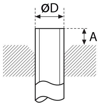
- Connect the pipes using two spanners, taking care not to damage the piping. If the tightening force is insufficient, then there may well be leaks. And if the tightening force is excessive, then there may also be leaks as the flange could be damaged. The safest system is constructed by tightening the connection using a fixed spanner and a dynamometric spanner: in this case, use the table "tightening torques for flange connections".
- We recommend you leave an extra 50~cm of pipe for any subsequent work carried out in the vicinity of the cocks.
2.8 Connections to the external unit
Screw the pipe unions onto the external unit connections with the same tightness as for the internal unit.
To avoid leaks, pay particular attention to the following points:
- Tighten the pipe unions, taking care not to damage the piping.
- If the tightening force is insufficient, then there may well be leaks. And if the tightening force is excessive, then there may also be leaks as the flange could be damaged.
- The safest system is constructed by tightening the connection using a dynamometric spanner: in this case, use the tables below (for copper piping).
TIGHTENING TORQUES FOR FLANGE CONNECTIONS
| Pipe | Tightening torque [kgf x cm] | Corresponding effort (using a 20 cm spanner) |
| 6.35 mm (1/4") | 160 - 200 | wrist force |
| 9.52 mm (3/8") | 300 - 350 | arm force |
| 12.70 mm (1/2") | 500 - 550 | arm force |
| 15.88 mm (5/8") | 630 - 770 | arm force |
TIGHTENING TORQUE FOR PROTECTION CAPS
| Tightening torque [kgf x cm] |
| Service connection | 70-90 |
| Protection caps | 250-300 |
LENGTH OF THE PIPING
The maximum length for the connection piping varies depending on the model. When the length is over 5m , take care to add the right amount of refrigerant per metre.
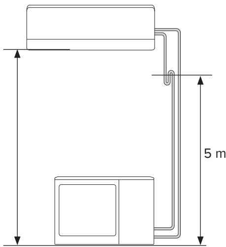
If you need to install the external and internal units with a height difference over 5m (fig. B and fig. C), use siphons on the gas piping in order to allow oil to return to the compressor properly.
NOTE:
We recommend making a loop in the piping near the external unit, so as to reduce the vibrations transmitted from that point.
IMPORTANT: CHECK FOR REFRIGERANT LEAKS
Once you have created the connections and a vacuum, open the cocks so that the gas fills the piping and always check for leaks using a leak detector (risk of personal injury from cold burns).
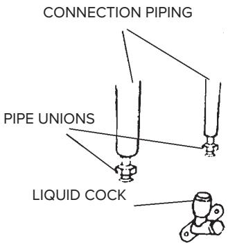
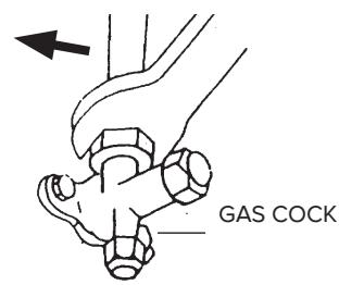
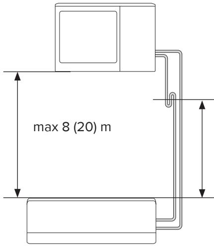
fig.B
2.9 Creating a vacuum and checking the seal
ATTENTION:
- The operations detailed below should be carried out after the power supply to the air conditioning unit has been switched off.
- Use tools specific to R32 (pressure unit, charging pipe, vacuum pump). Using the same vacuum pump for various different types of refrigerant could damage the pump or the unit.
- Do not release refrigerant into the atmosphere. In the event of a refrigerant leak, ventilate as much as possible.
- After having connected the pipes, check the joints for refrigerant leaks.
- Always protect the connection cables and pipes to prevent their being damaged, as they could cause gas leaks when damaged (personal injury from cold burns).
- In order to charge R32 into the system, the refrigerant must be in liquid form.
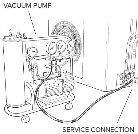
A vacuum pump suitable for use with R32 must be used to bleed the circuit.
Make sure the vacuum pump is filled with oil to the level indicated by the oil indicator light, and that the two cocks on the external unit are shut off:
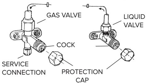
- unscrew the caps on the cocks of the two-way and three-way valves, and on the service valve;
- connect the vacuum pump to the small service valve in the external unit three-way valve;
- Fully open the low pressure valve, keeping the high pressure valve shut.
- Create the vacuum for approximately 20/25 minutes;
- Make sure the pressure gauge reads -0.101 MPa (-760 mmHg);
- Close the low pressure valve and switch off the pump. Check that the needle on the pressure gauge does not move for approximately 5 minutes. If the needle moves, this means that air is seeping into the system, and you must check all connections are tight enough and that the piping connections were all performed correctly. Then repeat the procedure from step 3.
- Disconnect the vacuum pump;
- Open the cocks on the two-way and three-way valves fully;
- Screw the plug tightly to the service outlet ensuring that it is well sealed,
- After having tightened all the plugs, check that there are no gas leaks around their circumference
ATTENTION:
Always protect the connection cables and pipes to prevent their being damaged, as they could cause gas leaks when damaged (personal injury from cold burns).
MONOSPLIT INSTALLATION TECHNICAL SPECIFICATIONS
| OUTDOOR UNIT MODEL | | NEVIS PLUS
25 MD0-O | NEVIS PLUS
35 MD0-O | NEVIS PLUS
50 MD0-O | MONO UNIV 70
MD0-O |
| Liquid pipe diameter | inches | 1/4 | 1/4 | 1/4 | 3/8 |
| Gas pipe diameter | inches | 3/8 | 3/8 | 1/2 | 5/8 |
| Maximum length of pipe with standard charge | m | 5 | 5 | 5 | 5 |
| Maximum pipe length* | m | 25 | 25 | 30 | 50 |
| Standard charge | kg | 0,8 | 0,95 | 1,48 | 2 |
| t CO2 eq. | 1,67 | 1,98 | 3,09 | 4,18 |
| Extra gas recharge | g/m | 15 | 15 | 15 | 30 |
| Maximum difference in height between internal and external unit** | m | 10 | 10 | 20 | 25 |
| Type of refrigerant | | R410A | R410A | R410A | R410A |
| GWP | | 2088 | 2088 | 2088 | 2088 |
MULTISPLIT INSTALLATION TECHNICAL SPECIFICATIONS
| OUTDOOR UNIT MODEL | | DUAL 50 XD0-O | TRIAL 80 XD0-O | QUAD 110 XD0-O | PENTA 121 XD0C-O |
| Liquid pipe diameter | inches | 2x 1/4 | 3x 1/4 | 4x 1/4 | 5x 1/4 |
| Gas pipe diameter | inches | 2x 3/8 | 3x 3/8 | 4x 3/8 | 4x 3/8 + 1x 1/2 |
| Maximum pipe length for single internal unit with standard charge | m | 5 | 5 | 5 | 5 |
| Maximum pipe length for single internal unit* | m | 20 | 25 | 30 | 30 |
| Maximum total length of piping (sum of internal units)* | m | 30 | 45 | 60 | 75 |
| Standard charge | kg | 1,9 | 2,4 | 3 | 3,6 |
| t CO2 eq. | 3,97 | 5,01 | 6,26 | 7,52 |
| Extra gas recharge | g/m | 15 | 15 | 10 | 10 |
| Maximum difference in height between internal and external unit (internal unit just above the external unit)** | m | 15 | 15 | 15 | 15 |
| Maximum difference in height between internal and external unit (internal unit just below the external unit)** | m | 10 | 10 | 10 | 10 |
| Maximum difference in height between internal units | m | 10 | 10 | 10 | 10 |
| Type of refrigerant | | R410A | R410A | R410A | R410A |
| GWP | | 2088 | 2088 | 2088 | 2088 |
() at the maximum distance, efficiency is approximately 90% .
(^*) with a difference in height over 5m , we recommend you include a trap.
2.10 Recovering the refrigerant
Procedure for returning all the refrigerant to the external unit:
- unscrew the caps from the cocks on the two-way and three-way valves.
- set the appliance to cooling mode (check whether the compressor works) and leave the appliance on for a few minutes.
- connect the pressure gauge.
- shut off the two-way valve.
- when the pressure gauge reads "0", shut off the three-way valve and turn the air conditioning unit off immediately.
- shut the caps on the valves.
WARNING:
Recharge refrigerant gas as necessary in accordance with the instructions provided for the product used, wearing protective clothing, avoiding sharp bursts of gas from the tank or from the system connections.
2.11 Charging the refrigerant gas
Before proceeding with the refrigerant charging operations, check that all the valves and cocks are shut.
N.B.: during initial installation, perform the procedure described in paragraph 2.9 "Creating a vacuum and checking the seal".
- Connect the low pressure connection of the pressure gauge to the service valve, and connect the refrigerant tank to the central inlet of the pressure gauge. Open the refrigerant tank and then open the cap on the central valve and work the pin valve until you hear the refrigerant exiting, then release the pin and screw the cap back on;
- Open the three-way valve and the two-way valve;
- Turn on the air conditioning unit in cooling mode. Leave it running for a few minutes;
- Place the refrigerant canister on the electronic scales and record its weight;
- Check the pressure shown on the pressure gauge;
- Open the "LOW" knob and allow the refrigerant to flow gradually;
- When the refrigerant charge in the circuit reaches the specified value (calculated by means of the difference in weight of the canister), shut off the "LOW" knob;
- When charging is complete, test operation by measuring the temperature of the gas pipe with the special thermometer: the temperature should be 5 to 8^ over the temperature read on the evaporation temperature section of the pressure gauge. Now check the stability of the pressure, by connecting the pressure gauge assembly to the three-way service valve. Open the two-way and three-way valves fully, turn on the air conditioning unit and check for refrigerant leaks using the leak detector (if there are any leaks, carry out the procedure described in paragraph 2.10 "Recovering the refrigerant");
- Disconnect the pressure gauge from the valve and turn the air conditioning unit off;
- Disconnect the tank from the pressure gauge and close all caps.
ATTENTION:
Do not release R32 into the atmosphere.
This appliance contains a fluorinated greenhouse gas, covered by the Kyoto Protocol, with a GWP^* = 675 . In other words, if 1 kg of this greenhouse gas were released into the atmosphere, the impact on global warming would be 675 times greater compared to 1 kg of CO_2 , over a period of 100 years.
In no case whatsoever must the user attempt to intervene on the refrigerant circuit or dismantle the product. In case of need, please contact a qualified professional.
(*) GWP is an acronym of "Global Warming Potential", referring to the greenhouse effect.
3. ELECTRICAL CONNECTIONS
WARNING:
Before performing any electrical connections, make sure that the units have been disconnected from the electricity supply and that the systems to which the equipment should be connected conform to current standards.
- Only use cables with a suitable cross-section.
- Leave some extra length on the connection cables to allow for future maintenance.
- Never connect the power supply cable by cutting it in half as this could cause a blaze.
- If the power supply cable is damaged, it must be replaced by the manufacturer or by its technical assistance service, or at least by a suitably qualified individual, in order to prevent all hazards.
NOTE:
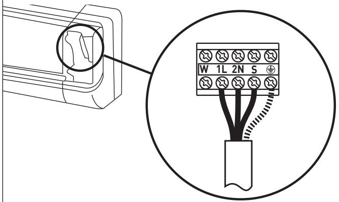
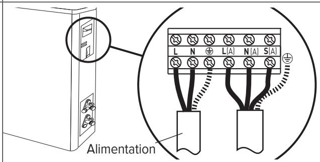
Strip both ends of the wires in the power supply cable and the internal - external unit connection cable, as indicated in the figure, and use the longest earth wire out of the active wires.
Make sure the wires do not come into contact with the piping or other metal parts.

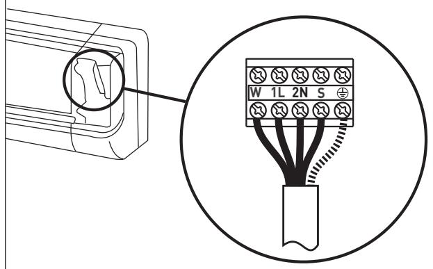
3.1 Connecting the internal unit
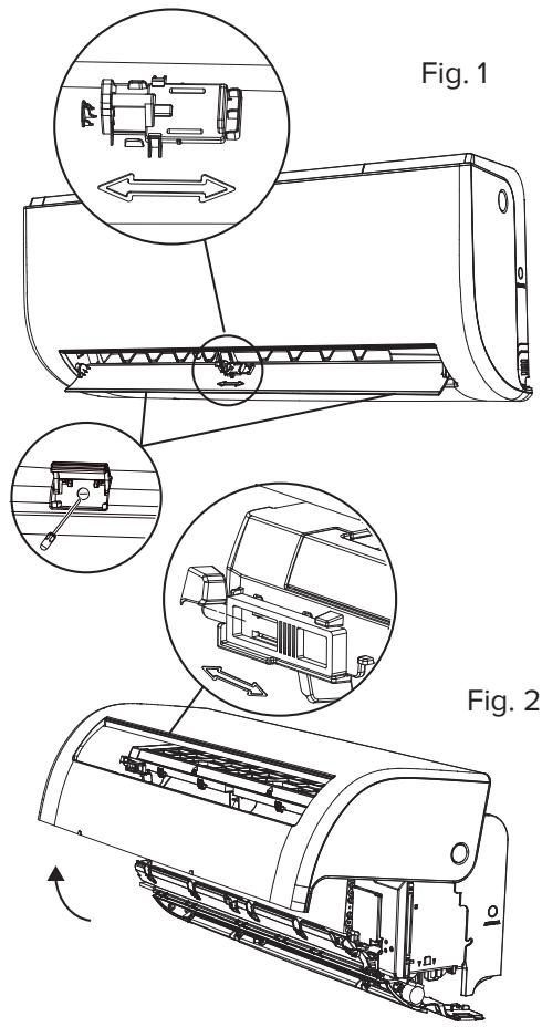
- Slide the clip on the flap, remove the screws (fig. 1). Rotate and lock the panel by the clips. Open connections box(fig. 2).
- Route the internal/external unit connection cable behind the internal unit and prepare the end of the cable.
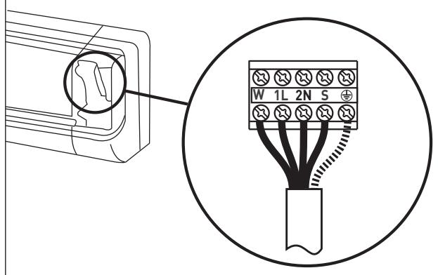
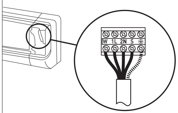
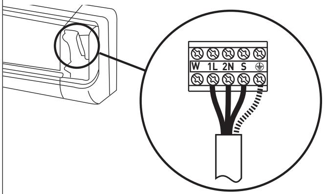
- Connect the conductors to the screw terminals in accordance with the numbering.
MONOSPLIT INSTALLATION
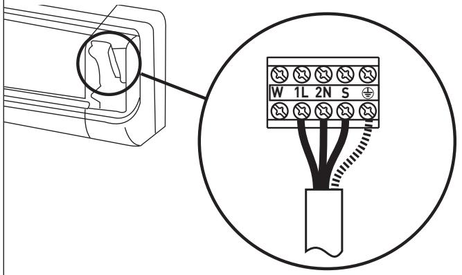
MULTISPLIT INSTALLATION
- Use the wire clamp situated underneath the electrical terminal board.
- Put the cover back in place, ensuring it is positioned correctly.
NOTE: the connection cables must not be routed near junction boxes, wireless data transmission systems (wifi routers) or other cables.
3.2 Connecting the external unit
- Remove the cover.
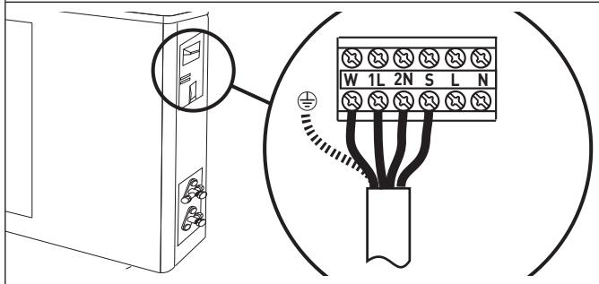
- Connect the wires to the screw terminals using the same numbering system as for the internal unit. Screw the terminal board screws tightly to avoid any loosening.
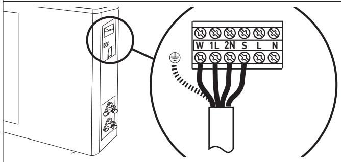
MONOSPLIT INSTALLATION
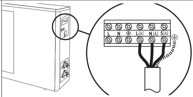
MULTISPLIT INSTALLATION
- Fasten the cables using the cable clamp.
- Put the cover back in place, ensuring it is positioned correctly.
3.3 Connecting to the mains electricity supply
Appliance connection must adhere to European and national standards, and must be protected by a 30mA differential switch. Connection to the mains must be permanent (not using a plug) and equipped with an omnipolar switch complying with current CEIEN standards (contact air gap of at least 3mm when open, preferably fitted with a fuse). Proper connection to an efficient earthing system is essential for ensuring safe operation of the device.
- Remove the cover.
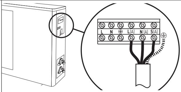
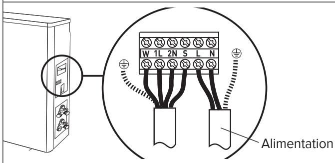
- Connect the conductors to the screw terminals. Screw the terminal board screws tightly to avoid any loosening.
- Fasten the cables using the cable clamp.
- Put the cover back in place, ensuring it is positioned correctly.
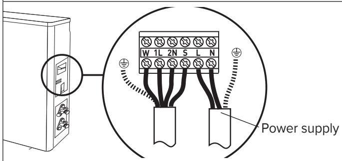
MONOSPLIT INSTALLATION
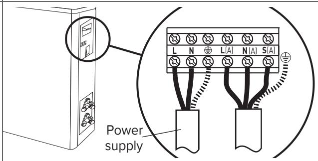
MULTISPLIT INSTALLATION
3.4 Connection types
MONOSPLIT INSTALLATION
| External unit model | Power supply | Switch type | Connection cable | Connection cable type | Power supply cable | Power supply cable type |
| NEVIS PLUS 25 MD0-O | 220-240 ~ 50 Hz | 20A | 5G 1,5 mm² | H07RN-F | 3G 1,5 mm² | H07RN-F |
| NEVIS PLUS 35 MD0-O | 220-240 ~ 50 Hz | 20A | 5G 1,5 mm² | H07RN-F | 3G 1,5 mm² | H07RN-F |
| NEVIS PLUS 50 MD0-O | 220-240 ~ 50 Hz | 20A | 5G 1,5 mm² | H07RN-F | 3G 1,5 mm² | H07RN-F |
MULTISPLIT INSTALLATION
| External unit model | Power supply | Switch type | Connection cable | Connection cable type | Power supply cable | Power supply cable type |
| DUAL 50 XDO-O | 220-240 ~ 50 Hz | 20A | 4G 1,5 mm² | H07RN-F | 3G 1,5 mm² | H07RN-F |
| TRIAL 80 XDOC-O | 220-240 ~ 50 Hz | 30A | 4G 1,5 mm² | H07RN-F | 3G 1,5 mm² | H07RN-F |
| QUAD 110 XDOC-O | 220-240 ~ 50 Hz | 30A | 4G 1,5 mm² | H07RN-F | 3G 2,5 mm² | H07RN-F |
| PENTA 121 XDOC-O | 220-240 ~ 50 Hz | 30A | 4G 1,5 mm² | H07RN-F | 3G 2,5 mm² | H07RN-F |
4. FINAL STAGES
WARNING:
- Use manual tools and equipment that are suitable for the intended purpose.
- Always protect the connection cables and pipes to prevent their being damaged, as they could cause gas leaks when damaged. (Personal injury from cold burns).
-
Recharge the refrigerant gas in accordance with the instructions provided on the product safety data sheet, while wearing protective clothing and avoiding sharp bursts of gas from the tank or from the system connections. (Personal injury from cold burns).
-
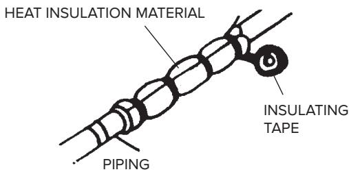
Wrap some insulating material around the joints of the internal unit and fasten it in place using electric (insulating) tape.
- Fasten the extra part of the signal cable to the piping or to the external unit.
- Fasten the piping to the wall (first cover the pipes with electric insulating tape) using some clips or otherwise fit the pipes into plastic channels.
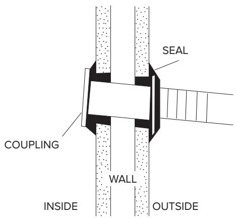
- Use a suitable seal to fill in the hole in the wall through which the piping passes so that no air or water can filter through.
- Outside, insulate all the bare piping, including all valves.
- If the piping has to pass above the ceiling or via a warm damp place, wrap all pipes with some extra insulating material available on sale to prevent condensation from forming.
4.1 Testing
Check the following points:
- INTERNAL UNIT
- Are the ON/OFF and FAN buttons working properly?
- Is the MODE button working properly?
- Are the buttons for the set-point and TIMER working properly?
- Do all the LEDs come on?
- Are the flaps used to direct the air flow efficient?
- Is the condensation drained regularly?
- EXTERNAL UNIT
- Is there any noise or vibration during operation?
- Could the noise, air flow or condensation drainage disturb the neighbours?
- Are there any refrigerant leaks?
NOTE:
The electronic control will only allow the compressor to start three minutes after the unit has been powered.
WARNING:
Before carrying out any work, make sure that the units have been disconnected from the electricity supply.
- Make sure the systems to which the appliance should be connected comply with current applicable standards.
Operation in Cooling mode - Visual checks on the Internal Unit
| Problem | Check | Action |
| 1 - Frost forms on the Internal Unit heat exchanger. | 1.A - Frost only at the bottom of the heat exchanger: gas leak.
1.B - Frost covers the entire heat ex-changer: the air filter is clogged.
The room temperature is low (< 20°C). | Find the leak and recharge.
Clean the air filter.
Unplug the appliance and switch off the dedicated switch before cleaning (risk of electrocution).
Check the room temp. |
| 2 - No condensation forms. | 2.A - If the Internal Unit heat exchanger remains dry and the electricity consumption is much lower than the rated value, then there is a leak. | Find the leak.
Replace the heat exchanger. |
| 3 - The compressor runs but there is little cooling. | 3.A - The External Unit heat exchanger is clogged or covered: you do not have a good heat exchange.
3.B - The flaps on the External Unit heat exchanger are bent. | Clean the External Unit heat exchanger.
Straighten the flaps on the external heat exchanger. |
| 4 - The air temperature is low, but there is little cooling. | 4.A - The Internal Unit filter is clogged.
4.B - The air recirculates in the Internal Unit.
4.C - The machine has not been sized correctly or is overloaded e.g.: heat sources, overcrowding,...). | Clean the filter.
Encourage the free circulation of air.
Replace the appliance or remove the overload. |
| 5 - The compressor does not start. | 5.A - The compressor is very hot: heat protection. | Wait for the temperature to drop. |
| 6 - The appliance comes to a stop after a few minutes of operation. | 6.A - The internal unit fan is broken. | Replace the motor.
Only use original spare parts. |
TROUBLESHOOTING - electrics
| Problem | Check | Action |
| 1 - The appliance gives no sign of life (no LEDs lit, no beeps sounded), not even when you press the ON-OFF button on the internal unit. | 1.A - Check whether there has been a power failure.
1.B - Check whether the plug is inserted fully in the socket in the wall.
1.C - Check whether the automatic switch has blown.
1.D - Check whether the selector has been set to stop. | •Restore the power supply and the correct connections.
•Plug the appliance in fully.
•Reset the automatic switch.
•Set the selector to another function. |
| 2 - The remote control does not work or only works from a short distance. | 2.A - Check whether the batteries are low.
2.B - Check whether there are any obstacles (curtains or ornaments) between the remote control and the air conditioning unit.
2.C - Check whether the distance between the remote control and the unit is too far. | •Replace the batteries.
•Remove all obstacles.
•Move closer to the air conditioning unit. |
INTRODUCTION
.1 Zone d-installation
INSTALLATION MONOSPLIT
INSTALLATION MULTISPLIT
INSTALLATION MONOSPLIT
INSTALLATION MULTISPLIT
INSTALLATION MONOSPLIT
INSTALLATION MULTISPLIT
3.4 Types de raccordement
INSTALLATION MONOSPLIT
m = 311 ;
INDICE:
INSTRUÇÉS DE UTILIZACão E MANUTENÇAO
REGRAS DE SEGURANÇA ..... pag. 101
- MODELO DE PAREDE . pag. 103
4. FASES CONCLUSIVAS
ATENCAO:
SPECIFICATIONS VOOR MONOSPLIT INSTALLATIONS
MONOSPLIT INSTALLATIE
MULTISPLIT INSTALLATION
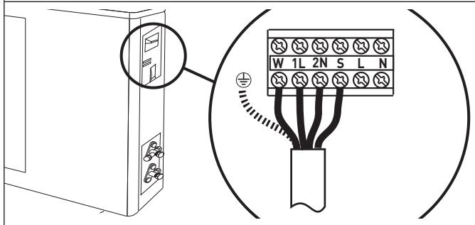
MONOSPLIT INSTALLATIE
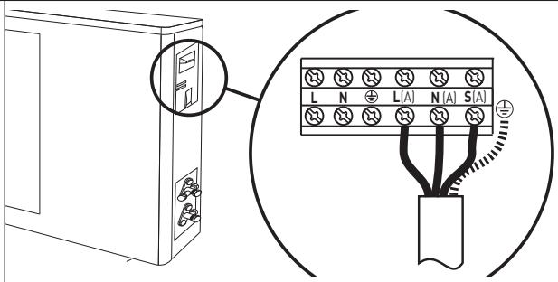
MULTISPLIT INSTALLATION
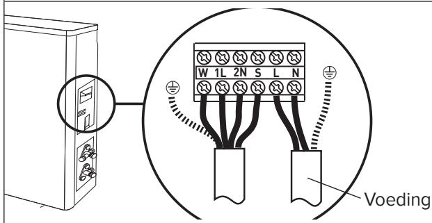
MONOSPLIT INSTALLATIE
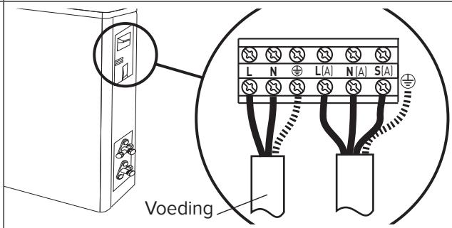
MULTISPLIT INSTALLATION
MONOSPLIT INSTALLATIE
| Model externe eenheid | Voeding | Type schakelaar | Verbindingskabel | Type verdin-dingskabel | Voedingskabel | Type voedings-kabel |
| NEVIS PLUS 25 MD0-O | 220-240 ~ 50 Hz | 20A | 5G 1,5 mm² | H07RN-F | 3G 1,5 mm² | H07RN-F |
| NEVIS PLUS 35 MD0-O | 220-240 ~ 50 Hz | 20A | 5G 1,5 mm² | H07RN-F | 3G 1,5 mm² | H07RN-F |
| NEVIS PLUS 50 MD0-O | 220-240 ~ 50 Hz | 20A | 5G 1,5 mm² | H07RN-F | 3G 1,5 mm² | H07RN-F |
MULTISPLIT INSTALLATIE
| Model externe
eenheid | Voeding | Type schake-
laar | Verbindingskabel | Type verbin-
dingskabel | Voedingskabel | Type voedings-
kabel |
| DUAL 50 XD0-O | 220-240 ~ 50 Hz | 20A | 4G 1,5 mm² | H07RN-F | 3G 1,5 mm² | H07RN-F |
| TRIAL 80 XD0-O | 220-240 ~ 50 Hz | 30A | 4G 1,5 mm² | H07RN-F | 3G 1,5 mm² | H07RN-F |
| QUADRI 110 XD0-O | 220-240 ~ 50 Hz | 30A | 4G 1,5 mm² | H07RN-F | 3G 2,5 mm² | H07RN-F |
| PENTA 121 XD0C-O | 220-240 ~ 50 Hz | 30A | 4G 1,5 mm² | H07RN-F | 3G 2,5 mm² | H07RN-F |
4. AFSLUITENDE FASEN
OPGELET:
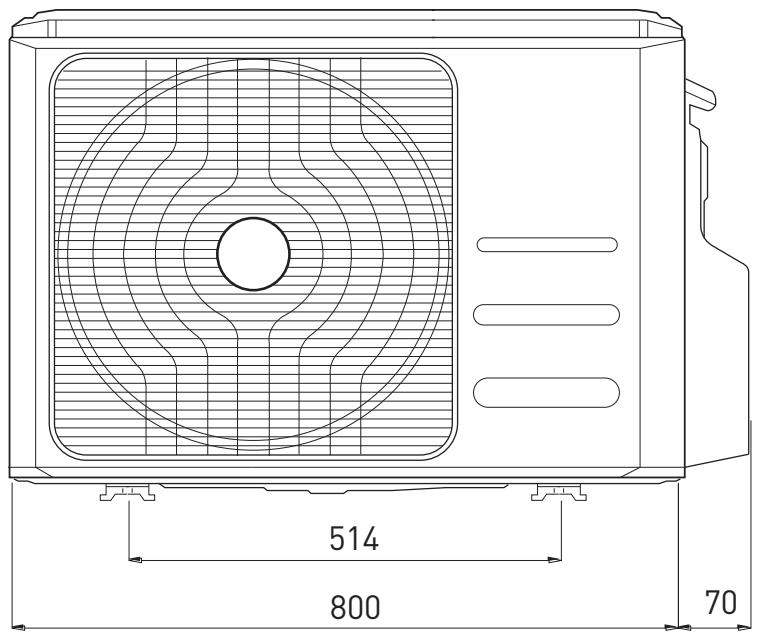
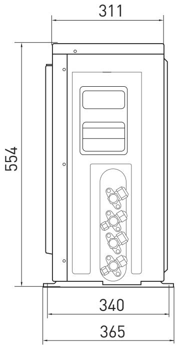
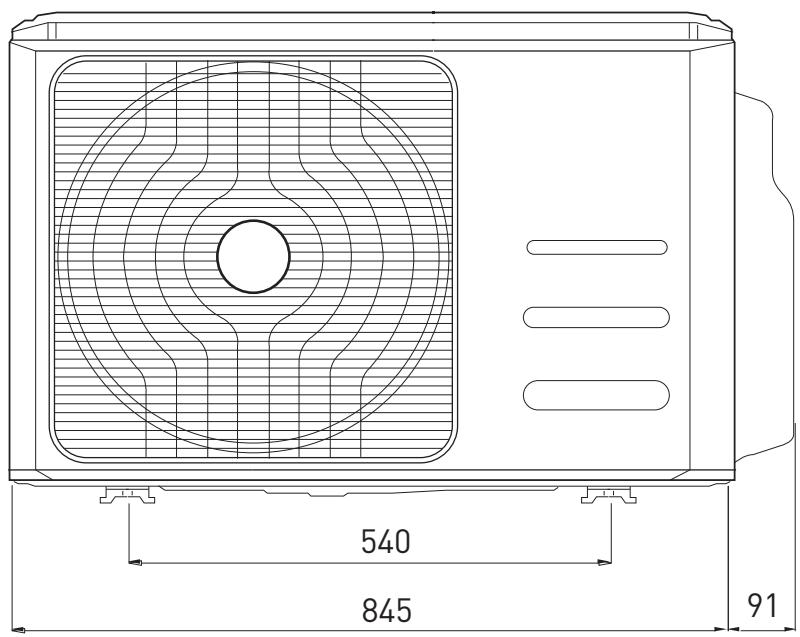
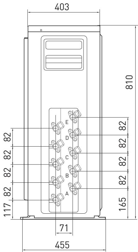
DIMENSIONI/ DIMENSIONS / DIMENSIONS DIMENSIONES / DIMENSOES/ AFMETINGEN
UNITA INTERNA/ INDOOR UNIT/ UNITE INTERNE/ UNIDAD INTERNA/ APARELHO INTERNO/ INTERNE EENHEID
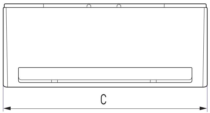
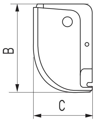
| MOD. | A | B | C |
| NEVIS PLUS 25 UDO-I | 716 | 300 | 193 |
| NEVIS PLUS 35 UDO-I | 804 | 300 | 193 |
| NEVIS PLUS 50 UDO-I | 964 | 325 | 222 |
UNITÁ ESTERNA/ OUTDOOR UNIT/ UNITE EXTERNE/ UNIDAD EXTERNA/ APARELHO EXTERNO/ I EXTERNE EENHEID
NEVIS PLUS 25 MD0-O; NEVIS PLUS 35 MD0-O; NEVIS PLUS 50 MD0-O
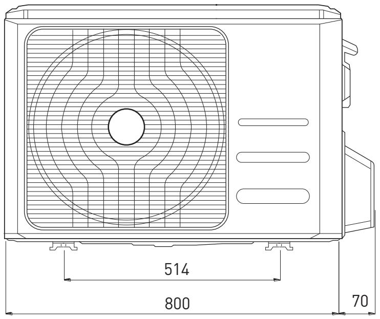
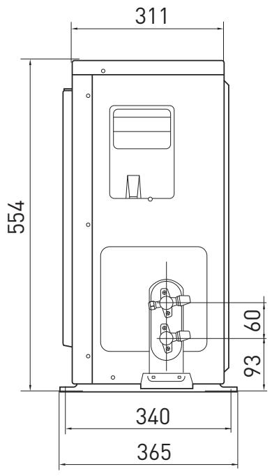
DUAL 50XD0-O
TRIAL 80 XDOC-O
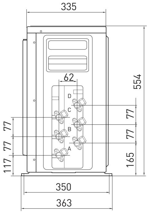
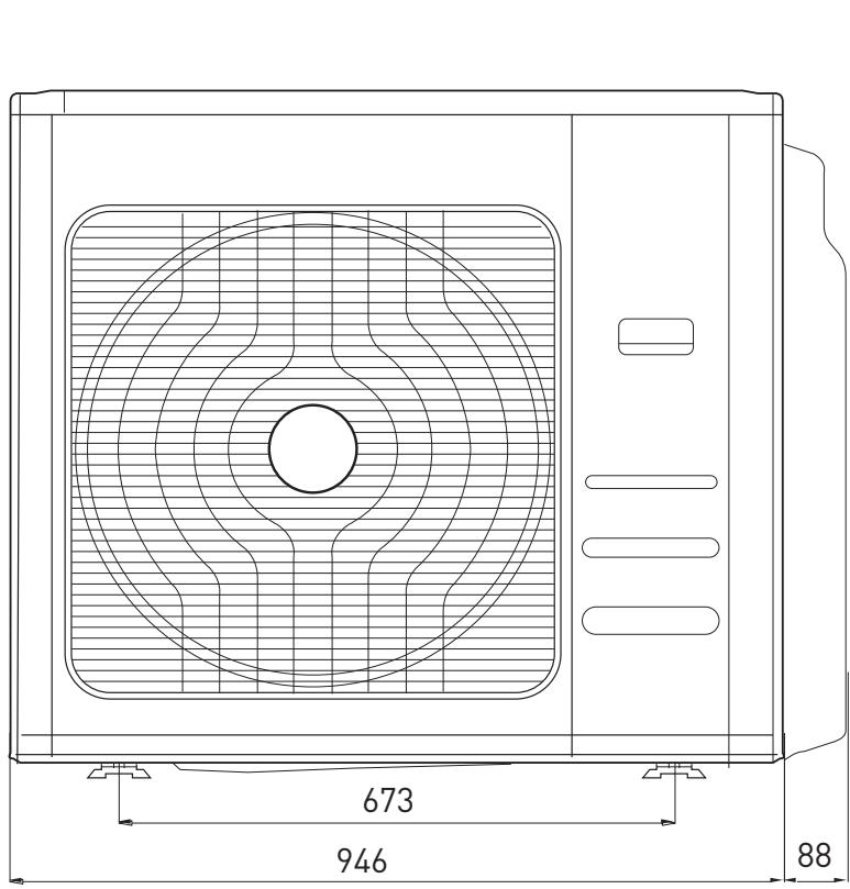
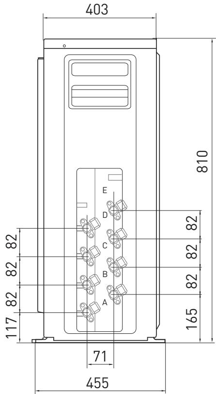
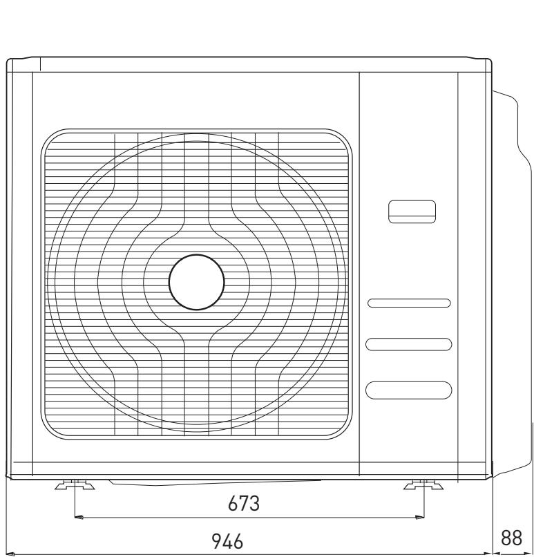
PENTA 121XD0C-O
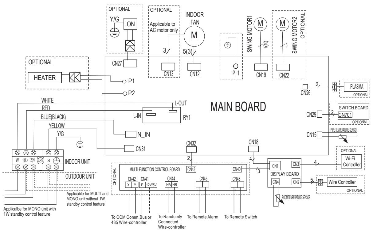
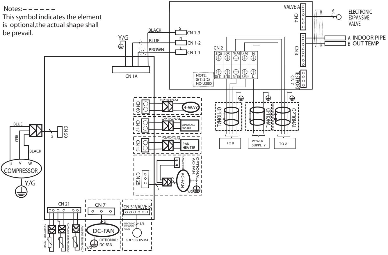
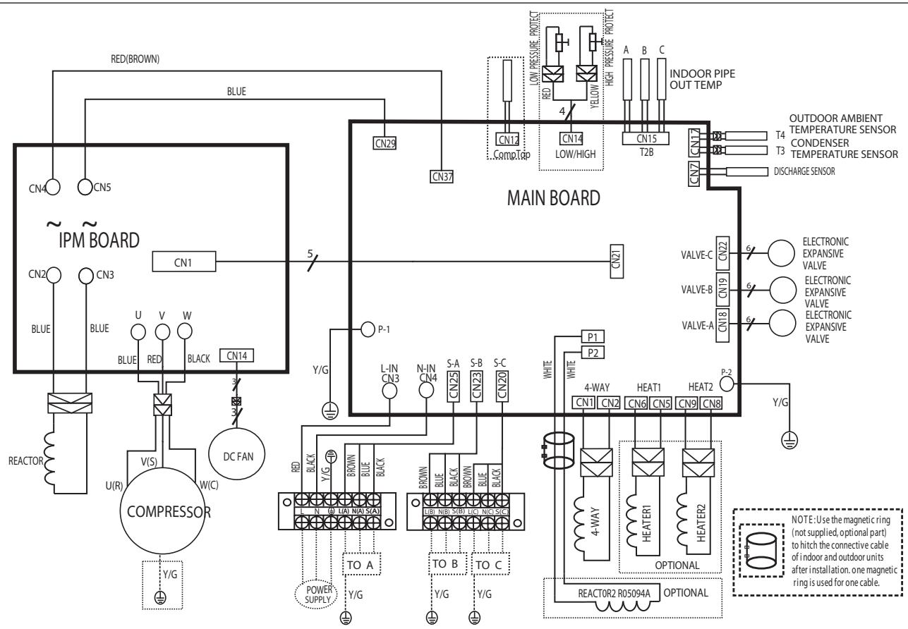
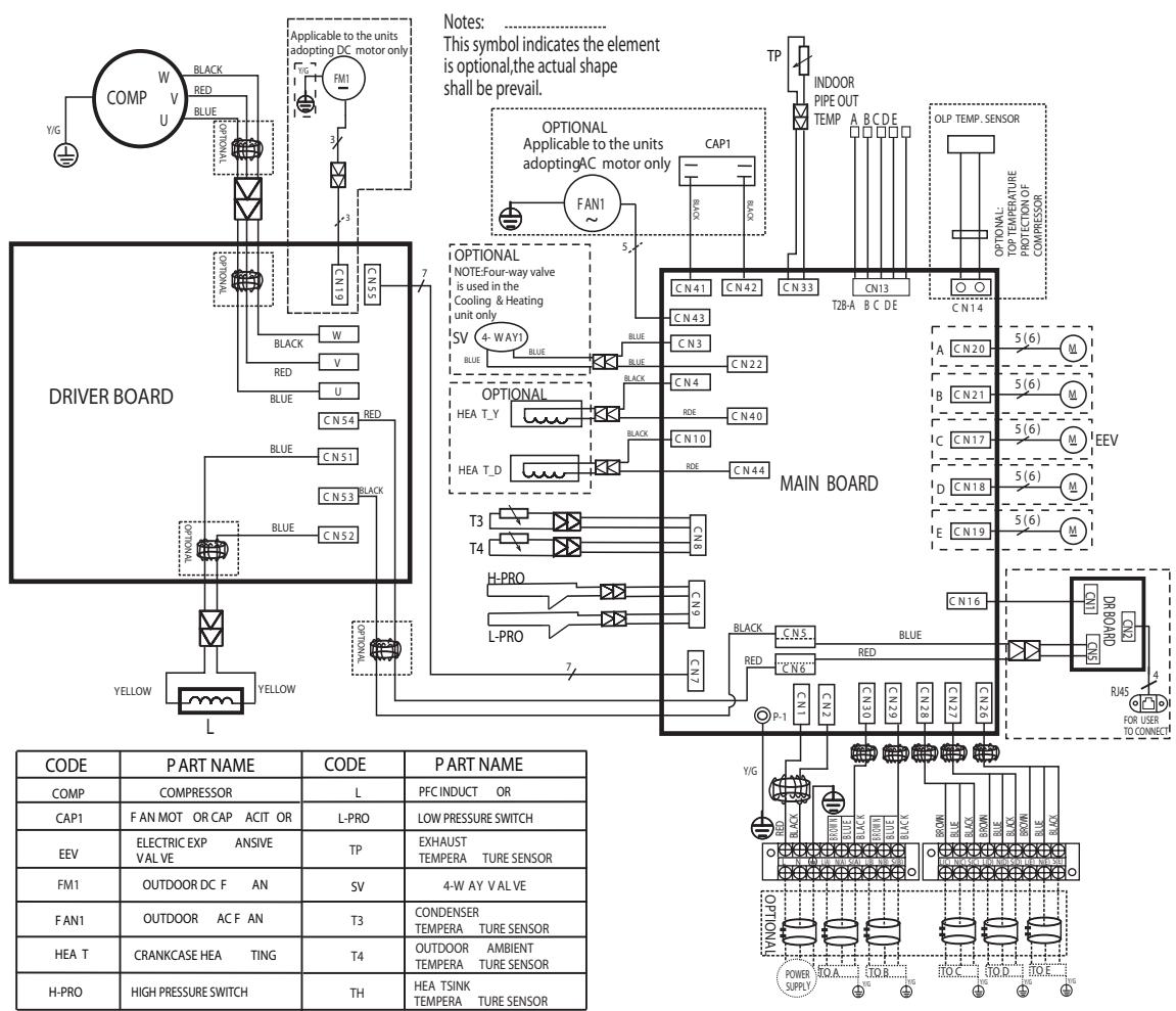
SCHEMI ELETTRICI - WIRING DIAGRAMS - SCHEMAS ÉLECTRIQUES ESQUÉMAS ÉLECTRICOS - ESQUÉMAS ÉLECTRICOS - ELEKTRISCHE SCHEMA'S
UNITA INTERNA/INDOOR UNIT/UNITE INTERNE/
UNIDAD INTERNA/ APARELHO INTERNO/ INTERNE EENHEID
NEVIS PLUS 25 UDO-I; NEVIS PLUS 35 UDO-I; NEVIS PLUS 50 UDO-I; NEVIS PLUS 70 MDO-I
UNITA ESTERNA/OUTDOOR UNIT/UNITE EXTERNE/
UNIDAD EXTERNA/ APARELHO EXTERNO/ I EXTERNE EENHEID
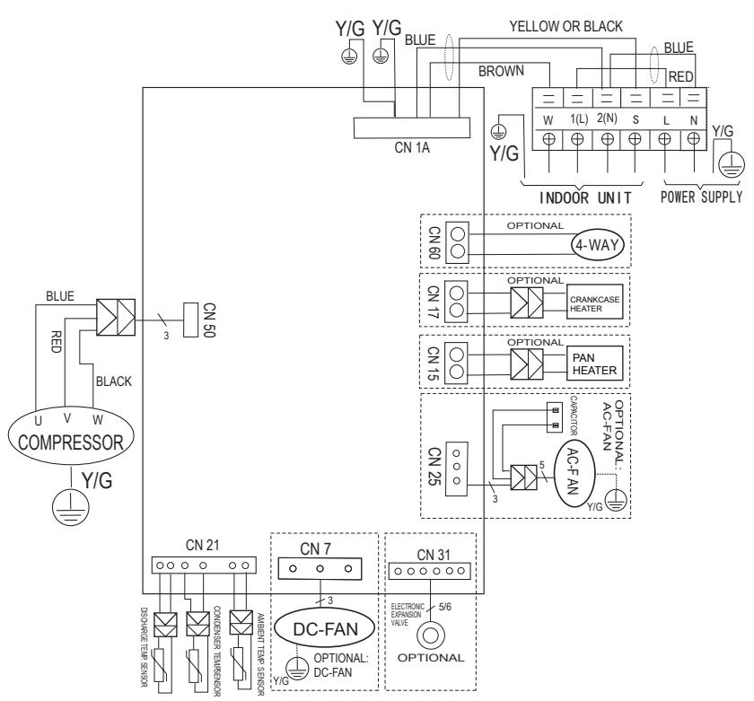
NEVIS PLUS 25 MD0-O
NEVIS PLUS 35 MD0-O
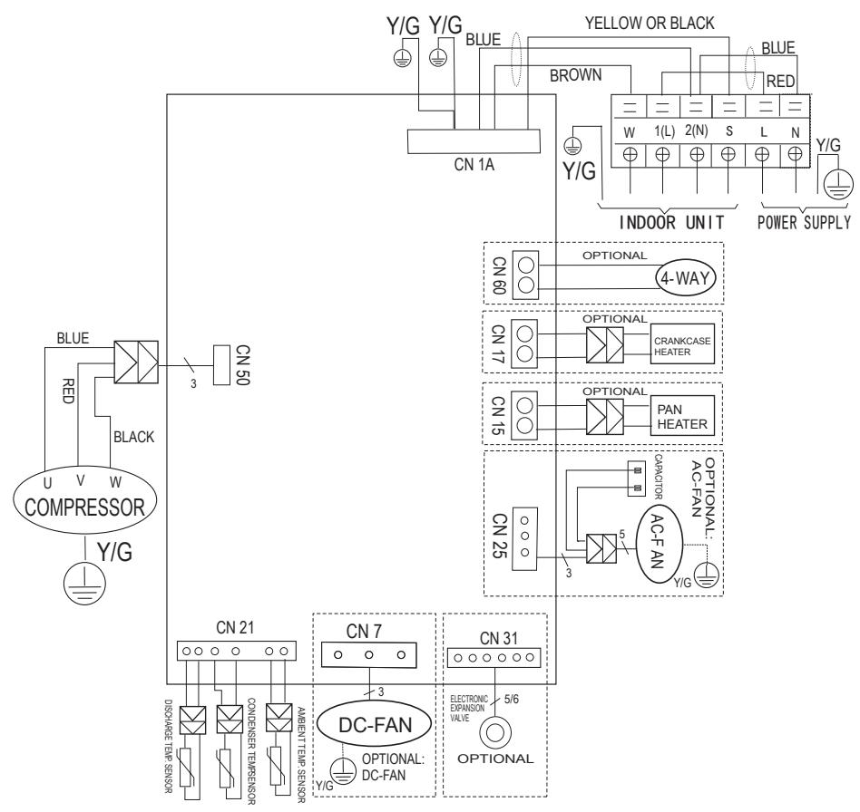
NEVIS PLUS 50 MDO-O
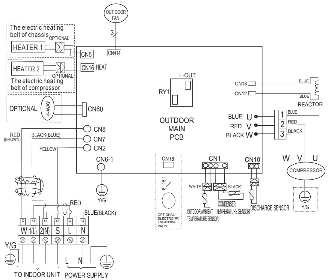
DUAL 50 XDOC-O
TRIAL 80 XDOC-O
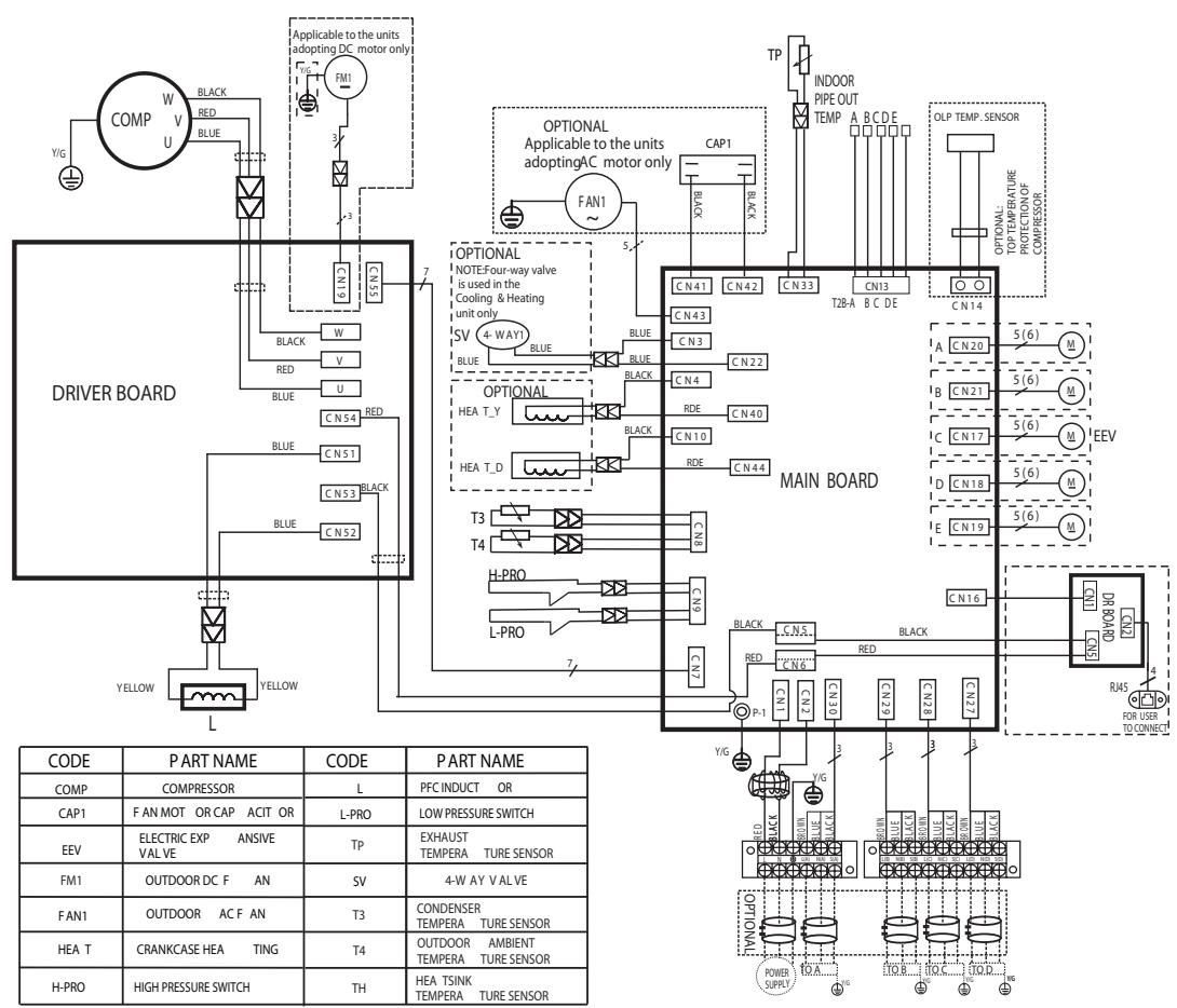
PENTA 121XD0C-O
- Model
- Power supply voltage
- Code
- Electricity supply frequency
- Nominal cooling capacity (MIN-MAX)
- Nominal heating capacity (MIN-MAX)
- Nominal cooling power absorption (MIN-MAX)
- Nominal heating power absorption (MIN-MAX)
- Max. absorbed power
- IP protection rating
- Weight
- Refrigerant gas
- GWP
- Amount of refrigerant gas
- Tonnes CO_2 equivalent.
- Type of protection from electric shocks
- Maximum circuit pressure (discharge)
- Maximum circuit pressure (suction)
- Serial number
- Manufacturer
LEGENDE (FR)