STILO COMFORT X - STILO DX - STILO SX - Range hood FABER - Free user manual and instructions
Find the device manual for free STILO COMFORT X - STILO DX - STILO SX FABER in PDF.
Download the instructions for your Range hood in PDF format for free! Find your manual STILO COMFORT X - STILO DX - STILO SX - FABER and take your electronic device back in hand. On this page are published all the documents necessary for the use of your device. STILO COMFORT X - STILO DX - STILO SX by FABER.
USER MANUAL STILO COMFORT X - STILO DX - STILO SX FABER
- Installation Instructions
- Use and Care Information
READ AND SAVE THESE INSTRUCTIONS
The Installer must leave these instructions with the homeowner. The homeowner must keep these instructions for future reference and for local electrical inspectors' use. READ THESE INSTRUCTIONS BEFORE YOU START INSTALLING THIS RANGEHOOD
WARNING: - TO REDUCE THE RISK OF A RANGE TOP GREASE FIRE: a) Never leave surface units unattended at high
settings. Boilovers cause smoking and greasy spillovers that may ignite. Heat oils slowly on low or medium setting. b) Always turn hood ON when cooking at high heat or when flambeing food (i.e. Crepes Suzette, Cherries Jubilee, Peppercorn Beef Flambé). c) Clean ventilating fans frequently. Grease should not be allowed to accumulate on fan or filter. d) Use proper pan size. Always use cookware appropriate for the size of the surface element.
WARNING: - TO REDUCE THE RISK OF INJURY TO PERSONS IN THE EVENT OF A RANGE TOP GREASE FIRE, OBSERVE
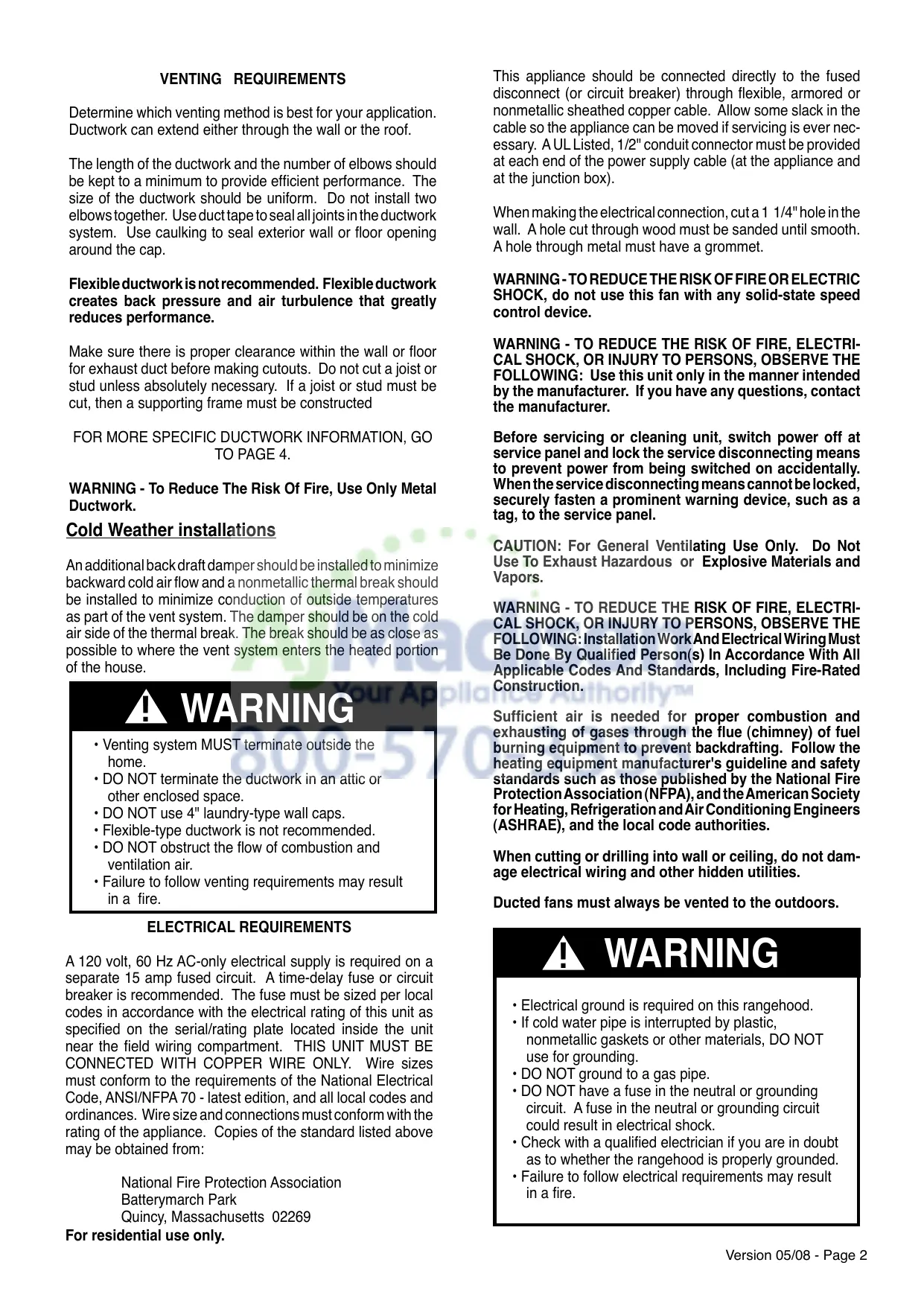
TO PAGE 4. WARNING - To Reduce The Risk Of Fire, Use Only Metal Ductwork. Cold Weather installations An additional back draft damper should be installed to minimize backward cold air flow and a nonmetallic thermal break should be installed to minimize conduction of outside temperatures as part of the vent system. The damper should be on the cold air side of the thermal break. The break should be as close as possible to where the vent system enters the heated portion of the house. ! WARNING
- Venting system MUST terminate outside the home.
- DO NOT terminate the ductwork in an attic or other enclosed space.
- DO NOT use 4" laundry-type wall caps.
- Flexible-type ductwork is not recommended.
- DO NOT obstruct the flow of combustion and ventilation air.
- Failure to follow venting requirements may result in a fire. ELECTRICAL REQUIREMENTS A 120 volt, 60 Hz AC-only electrical supply is required on a separate 15 amp fused circuit. A time-delay fuse or circuit breaker is recommended. The fuse must be sized per local codes in accordance with the electrical rating of this unit as specified on the serial/rating plate located inside the unit near the field wiring compartment. THIS UNIT MUST BE CONNECTED WITH COPPER WIRE ONLY. Wire sizes must conform to the requirements of the National Electrical Code, ANSI/NFPA 70 - latest edition, and all local codes and ordinances. Wire size and connections must conform with the rating of the appliance. Copies of the standard listed above may be obtained from: National Fire Protection Association Batterymarch Park Quincy, Massachusetts 02269 For residential use only. Before servicing or cleaning unit, switch power off at service panel and lock the service disconnecting means to prevent power from being switched on accidentally. When the service disconnecting means cannot be locked, securely fasten a prominent warning device, such as a tag, to the service panel. CAUTION: For General Ventilating Use Only. Do Not Use To Exhaust Hazardous or Explosive Materials and Vapors. WARNING - TO REDUCE THE RISK OF FIRE, ELECTRICAL SHOCK, OR INJURY TO PERSONS, OBSERVE THE FOLLOWING: Installation Work And Electrical Wiring Must Be Done By Qualified Person(s) In Accordance With All Applicable Codes And Standards, Including Fire-Rated Construction. Sufficient air is needed for proper combustion and exhausting of gases through the flue (chimney) of fuel burning equipment to prevent backdrafting. Follow the heating equipment manufacturer's guideline and safety standards such as those published by the National Fire Protection Association (NFPA), and the American Society for Heating, Refrigeration and Air Conditioning Engineers (ASHRAE), and the local code authorities. When cutting or drilling into wall or ceiling, do not damage electrical wiring and other hidden utilities. Ducted fans must always be vented to the outdoors.
- Electrical ground is required on this rangehood.
- If cold water pipe is interrupted by plastic, nonmetallic gaskets or other materials, DO NOT use for grounding.
- DO NOT ground to a gas pipe.
- DO NOT have a fuse in the neutral or grounding circuit. A fuse in the neutral or grounding circuit could result in electrical shock.
- Check with a qualified electrician if you are in doubt as to whether the rangehood is properly grounded.
- Failure to follow electrical requirements may result in a fire. Version 05/08 - Page 2
- Phillips Screwdriver
- Flat Blade Screwdriver
- Wire Stripper or Utility Knife
This rangehood can be installed as either ducted or ductless. The blower can be vented through the wall or ceiling. To vent through a wall, a 90° elbow is used. When installed ductless, the rangehood vents out of grates on the sides of the chimney. Ductless installations require a Ductless Conversion Kit, available from your dealer. WARNING! BEFORE MAKING ANY CUTS OR HOLES FOR INSTALLATION, DETERMINE WHICH VENTING METHOD WILL BE USED AND CAREFULLY CALCULATE ALL MEASUREMENTS. RANGEHOOD COMPONENTS
OPTIONAL ACCESSORIES AVAILABLE
- Backsplash Choose either 24" or 30" high, mounts to the wall beneath the rangehood for a coordinated look 30" X 24" high part # 6098835 - Stainless 30" X 30" high part # 620000095- Stainless 36" X 24" high part # 6098815 - Stainless 36" X 30" high part # 620000096- Stainless
- High Ceiling Chimney Kit One 40" upper chimney to replace 16 1/8" upper chimney that came with hood part # 620000362 - Stainless
- *Ductless Conversion Kit For non-vented installations only
- it is highly recommended that professional style cooking always be vented to the outside part #620000363 - Stainless
- Replacement Charcoal Filter For non-vented installations only, replace charcoal filter as needed part # 620000041 ! WARNING
PERSONAL INJURY HAZARD
Because of the weight and size of the rangehood canopy, two or more people are needed to move and safely install the rangehood canopy. Failure to properly lift rangehood could result in damage to the product or personal injury.
The ductrun should not exceed 35 equivalent feet if ducted with the required minimum of 6" round duct. Calculate the length of the ductwork by adding the equivalent feet in FIGURE 2 for each piece of duct in the system. An example is given in FIGURE 3. 45˚ Elbow 90˚ Elbow 90˚ Flat Elbow Wall Cap FIGURE 2
9 Feet Straight Duct
For best results, use no more than three 90° elbows. Make sure that there is a minimum of 24" of straight duct between elbows if more than one is used. Do not install two elbows together. If you must elbow right away, do it as far away from the hood's exhaust opening as possible. Version 05/08 - Page 4 (vented to the outside) DUCTED INSTALLATION The Stilo chimneys are adjustable and designed to meet varying ceiling heights as indicated in FIGURE 4A. The chimneys can be adjusted for ceilings between 7' 4 3/4" and 8' 9 3/4" depending on the distance between the bottom of the hood and the cooktop (distance x). For shorter ceilings, have the chimney cover(s) cut at a sheet metal shop. For higher ceiling installations, the High Ceiling Chimney Kit includes a new 40” upper chimney which would replace the 16 1/8” upper chimney that came with the hood. DIMENSIONS 5 1/8” min 16 1/8” max upper chimney cover 21 1/4” lower chimney cover canopy 2 3/8" 19 9/32"
36” x = distance from hood to cooktop (varies depending on installation) min - 24”, suggested max - 30” also consult cooktop manufacturer's recommendation min & max ceiling height examples x = 24" min 7' 4 3/4" max 8' 3 3/4" x = 26" min 7' 6 3/4" max 8' 5 3/4" x = 28" min 7' 8 3/4" max 8' 7 3/4" x = 30" min 7' 10 3/4" max 8' 9 3/4" cabinet base
FIGURE 4A DUCTED INSTALLATIONS
Version 05/08 - Page 5 (not vented to the outside) DUCTLESS INSTALLATION 10" min 16 1/8” max The Stilo chimneys are adjustable and designed to meet varying ceiling heights as indicated in FIGURE 4B. For ductless installations, the chimneys can be adjusted for ceilings between 7' 9 5/8" and 8' 9 3/4" depending on the distance between the bottom of the hood and the cooktop (distance x). For shorter ceilings, have the chimney cover(s) cut at a sheet metal shop. For higher ceiling installations, the High Ceiling Chimney Kit includes a new 40” upper chimney which would replace the 16 1/8” upper chimney that came with the hood. 21 1/4" DIMENSIONS upper chimney cover ductless lower chimney cover canopy 2 3/8" 19 9/32"
36” x = distance from hood to cooktop (varies depending on installation) min - 24”, suggested max - 30” also consult cooktop manufacturer's recommendation min & max ceiling height examples x = 24" min 7' 9 5/8" max 8' 3 3/4" x = 26" min 7' 11 5/8" max 8' 5 3/4" x = 28" min 8' 1 5/8" max 8' 7 3/4" x = 30" min 8' 3 5/8" max 8' 9 3/4" cabinet base
1. Disconnect and move freestanding range from cabinet opening to provide easier access to rear wall. Put a thick, protective covering over cooktop, set-in range or countertop to protect from damage or dirt.
2. Determine and clearly mark with a pencil the center line on the
wall where the rangehood will be installed. 3. Based on your ceiling height and/or personal preference, determine the distance you would like between the bottom of the hood and the cooktop (distance X in FIGURE 4A OR 4B). Draw a horizontal line the height of distance X plus 12 3/4" (as indicated in FIGURE 5).
INSTALL THE RANGEHOOD
1. Remove the grease
filters from the unit by pulling the knob forward while turning it to the left, releasing the locking lever. FIGURE 6
2. Before mounting the CANOPY SECTION, tighten the two
leveling screws located near the CANOPY SECTION mounting points as indicated in FIGURE 7. FIGURE 7 FIGURE 5
4. Place the UPPER CHIMNEY MOUNTING BRACKET (E) on
the wall as shown 1/16" from the ceiling, aligning the center notch with the vertical center line. Mark the wall at the centers of the holes in the bracket.
5. Place the LOWER CHIMNEY MOUNTING BRACKET (E) on
the wall as shown at 16 1/8" below the upper bracket, aligning the center notch with the vertical center line. Mark the wall at the centers of the holes in the bracket.
6. Install the CHIMNEY MOUNTING BRACKETS (E) on the wall
using the MOUNTING SCREWS (D) provided.
3. Hook the body on to the MOUNTING SCREWS (D in FIGURE 7) and fully tighten the MOUNTING SCREWS.
4. Adjust the leveling screws to level the CANOPY SECTION.
5. For ducted installations, the DAMPER (G in FIGURE 1)
must be attached to the exhaust opening on the top of the CANOPY SECTION. Connect the ductwork and seal all connections with duct tape. PROCEED TO "FOR ALL INSTALLATIONS" ON NEXT PAGE
7. For the most secure installation, the MOUNTING SCREWS (D)
which mount the CANOPY SECTION (A in FIGURE 1) should be installed into wood. Mark the wall along the horizontal line 4 9/16" in from the center line on either side (as indicated in FIGURE 5A or 5B) and install the MOUNTING SCREWS into the wall leaving about 1/4" gap between the wall and the head of the screw.
8. For ducted installations, determine and make all necessary
cuts in the wall for the ductwork. Install the ductwork before the rangehood.
9. Determine the proper location for the Power Supply Cable by
1) Allows the LOWER CHIMNEY COVER to hide the Field Wiring
2) Does not have ductwork blocking your access to the Field Wiring
Compartment. Use a 1 1/4" Drill Bit to make this hole. Run the Power Supply Cable. Use caulking to seal around the hole. DO NOT turn on the power until installation is complete. Version 05/08 - Page 7
FOR ALL INSTALLATIONS
1. Remove the cover from the Field Wiring Compartment with a
phillips screwdriver. Feed the Power Supply Cable through the electrical knockout. Connect the Power Supply Cable to the rangehood cable. Attach the Power Supply Cable grounding lead to the green screw provided. Attach the White lead of the power supply to the White lead of the rangehood with a twist-on type wire connector. Attach the Black lead of the power supply to the Black lead of the rangehood with a twist-on type wire connector. Using the 4 holes provided screw the Field Wiring Compartment to the wall as dictated by your Power Supply Cable location (screws not provided). Replace the cover.
2. Install the UPPER CHIMNEY COVER (C in FIGURE 10) by slightly
widening the two sides and hooking them behind the CHIMNEY MOUNTING BRACKETS (E). Secure the sides to the CHIMNEY MOUNTING BRACKETS with the 4 CHIMNEY SCREWS (G).
3. Install the LOWER CHIMNEY COVER (B) by slightly widening
the two sides of the LOWER CHIMNEY COVER and hooking them between the UPPER CHIMNEY COVER and the wall making sure that it fits snugly. Secure the LOWER CHIMNEY COVER to the CANOPY SECTION (A) with 2 CHIMNEY SCREWS (G).
FOR DUCTLESS INSTALLATIONS
Ductless installations require a Ductless Conversion Kit whose components are pictured in FIGURE 8. Do not use the DAMPER (H in FIGURE 1) for ductless installations. The LOWER CHIMNEY COVER (B in FIGURE 1) should be discarded and replaced by a new one with holes (1 in FIGURE 8).
1. As indicated in FIGURE 8, fit the DUCTLESS DIVERTER
(5) over the duct outlet. Fit the 2 DIVERTER EXTENSION HORIZONTAL pieces (4) on either side of the DUCTLESS DIVERTER.
2. Install the CHARCOAL FILTER (6) behind the center grease
filter opening by inserting and locking into place, as indicated in FIGURE 9. FIGURE 9 FIGURE 10 FOR DUCTLESS INSTALLATIONS Fit the LEFT AND RIGHT VENT GRIDS (2 and 3) into the LOWER CHIMNEY DUCTLESS holes, making sure that the directional symbols are towards the top and front of the hood and that they connect snugly to the DIVERTER EXTENSION HORIZONTAL pieces. FIGURE 11 Version 05/08 - Page 8
FOR ALL INSTALLATIONS
1. Install the grease filters using two hands by first pulling and
turning the knob to the left so that the locking lever does not protrude from the filter (as in FIGURE 12). Insert the opposite end of the filter into the retaining channel. Insert the knob end next, then turn knob to the right to lock the filter into place. Rangehood Control Panel The control panel is located on the front edge of the rangehood canopy. The position and function of each control button are indicated in FIGURE 13. Light On/Off Button ( L ) On/Off switch for the halogen lights. Push the button in to turn the light ON, push again to turn the light OFF. FIGURE 13 Blower Indicator Light ( I ) Lights up to indicate blower is ON. FIGURE 12
2. Turn the power supply on. Turn on blower and lights. If the
rangehood does not operate, check that the circuit breaker is not tripped or the house fuse blown. If the unit still does not operate, disconnect the power supply and check that the wiring connections have been made properly. WIRING DIAGRAM Blower On/Off and Speed Buttons ( 1, 2, 3 ) Push button (1) to turn ON and OFF the blower. This button must be pushed in for the blower to operate regardless of speed chosen. Button (1) operates the blower on LOW speed. Push button (2) for MEDIUM speed. Push button (3) for HIGH speed. Cleaning The stainless steel grease filters should be cleaned frequently in hot detergent solution or washed in the dishwasher. Stainless steel cleaner should be used on stainless rangehoods. Abrasives and scouring agents can scratch stainless steel finishes and should not be used to clean finished surfaces. Replacing the Lamps Before attempting to replace the lamps, make sure that the light switch is turned off. Remove the 2 screws (as indicated in FIGURE 14) that hold the light support and gently pull the support down from the hood. Remove the lamp from the light support and replace with new lamp. Replace the light support and fix it into place with the 2 screws. An alternative method to replace the lamps is to use a 1 1/4" suction cup (FIGURE 15). Attach the suction cup to the bulb and pull firmly down on the bulb and replace with a new lamp.
- This rangehood uses 20 watt MR-11 halogen lamps w/ cover.
USE AND CARE INFORMATION
This rangehood system is designed to remove smoke, cooking vapors and odors from the cooktop area. FIGURE 14 For Best Results Start the rangehood several minutes before cooking to develop proper airflow. Allow the unit to operate for several minutes after cooking is complete to clear all smoke and odors from the kitchen. FIGURE 15 Version 05/08 - Page 9 FABER WARRANTY & SERVICE (SAVE FOR YOUR RECORDS) All Faber products are warranteed against any defect in materials or workmanship for the original purchaser for a period of 1 year from the date of original purchase. This warranty covers labor and replacement parts. To obtain warranty service, contact the dealer from whom you purchased the rangehood, or the local Faber distributor. If you cannot identify a local Faber distributor, contact us at (508) 358-5353 for the name of a distributor in your area. The Following is not covered by Faber's warranty:
1. Service calls to correct the installation of your range hood, to instruct you how to use your
range hood, to replace or repair house fuses or to correct house wiring or plumbing.
2. Service calls to repair or replace range hood light bulbs, fuses or filters. Those
consumable parts are excluded from warranty coverage.
3. Repairs when your range hood is used for other than normal, single-family
4. Damage resulting from accident, alteration, misuse, abuse, fire, flood, acts of God,
improper installation, installation not in accordance with electrical or plumbing codes, or use of products not approved by Faber.
5. Replacement parts or repair labor costs for units operated outside the United States or
Canada, including any non-UL or C-UL approved Faber rangehoods.
6. Repairs to the hood resulting from unauthorized modifications made to the
7. Expenses for travel and transportation for product service in remote locations and pickup
and delivery charges. Faber range hoods should be serviced in the home. Record Your Information Below: Serial #: __________________________ Date of Purchase: ______________ Version 05/08 - Page 10