EXP34U338HW - Air-conditioner ELECTROLUX - Free user manual and instructions
Find the device manual for free EXP34U338HW ELECTROLUX in PDF.
| Brand | Electrolux |
| Model | EXP34U338HW |
| Category | Mobile monoblock air conditioner |
| Power supply | 220-240 V ~ 50 Hz, 10 A |
| Operating modes | Cooling, Heating, Dehumidification, Ventilation, Auto |
| Remote control | Yes, with 3 V DC lithium button cell (type RG15D/E-ELL) |
| Air filter | Washable, clean every 2 weeks |
| Drainage | Manual via bottom plug or via pump with hose (heating/dehumidification mode) |
| Exhaust hose | Extendable length from 38 cm to 150 cm |
| Minimum room area | Greater than 12 m² |
| Compressor protection | 3-minute delayed start |
| Grounding | Mandatory, cord with ground wire |
| Set temperature range | 16 °C to 32 °C |
| Temperature display | In °C or °F (switchable) |
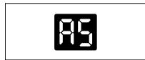
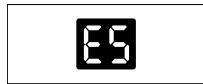
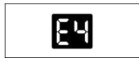
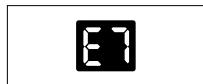
| Error codes displayed | A5 (room sensor), E5 (evaporator sensor), E4 (communication), P1 (tank full), E7 (indoor motor) |
| Included accessories | Exhaust hose, sliding window kit, extendable rod, drain hose with adapter, remote control, screws, decorative film, tie strap |
| Recommended cleaning | Filter every 2 weeks; body with soft cloth and soapy water |
| Winter storage | Drain water, cover or repackage |
| Energy efficiency class | Not specified |
| Refrigerant | Flammable (type not specified in manual, probably R290) |
Frequently Asked Questions - EXP34U338HW ELECTROLUX
User questions about EXP34U338HW ELECTROLUX
0 question about this device. Answer the ones you know or ask your own.
Ask a new question about this device
Download the instructions for your Air-conditioner in PDF format for free! Find your manual EXP34U338HW - ELECTROLUX and take your electronic device back in hand. On this page are published all the documents necessary for the use of your device. EXP34U338HW by ELECTROLUX.
USER MANUAL EXP34U338HW ELECTROLUX
WE'RE THINKING OF YOU
Thank you for purchasing an Electrolux appliance. You've chosen a product that brings with it decades of professional experience and innovation. Ingenious and stylish, it has been designed with you in mind. So whenever you use it, you can be safe in the knowledge that you'll get great results every time. Welcome to Electrolux.
Visit our website to:

Get usage advice, brochures, trouble shooter, service information: www.electrolux.com/webselfservice

Register your product for better service: www.registerelectrolux.com

Buy Accessories, Consumables and Original spare parts for your appliance: www.electrolux.com/shop
CUSTOMER CARE AND SERVICE
Always use original spare parts.
When contacting our Authorised Service Centre, ensure that you have the following data available: Model, PNC, Serial Number.
The information can be found on the rating plate.

Warning / Caution-Safety information.

General information and tips.

Environmental information.
Subject to change without notice.
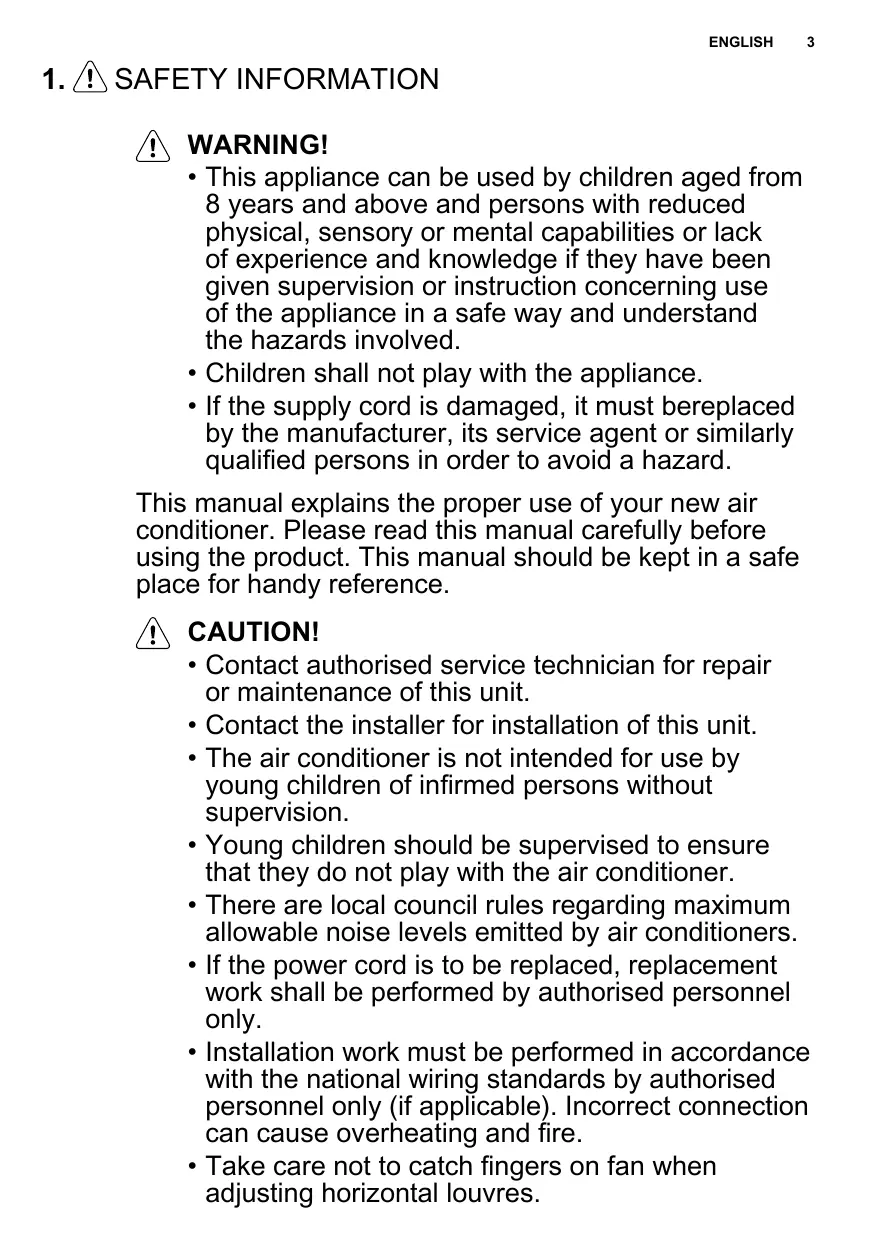
1. ⚠️ SAFETY INFORMATION

WARNING!
- This appliance can be used by children aged from 8 years and above and persons with reduced physical, sensory or mental capabilities or lack of experience and knowledge if they have been given supervision or instruction concerning use of the appliance in a safe way and understand the hazards involved.
• Children shall not play with the appliance. - If the supply cord is damaged, it must bereplaced by the manufacturer, its service agent or similarly qualified persons in order to avoid a hazard.
This manual explains the proper use of your new air conditioner. Please read this manual carefully before using the product. This manual should be kept in a safe place for handy reference.

CAUTION!
- Contact authorised service technician for repair or maintenance of this unit.
- Contact the installer for installation of this unit.
- The air conditioner is not intended for use by young children of infirmed persons without supervision.
- Young children should be supervised to ensure that they do not play with the air conditioner.
- There are local council rules regarding maximum allowable noise levels emitted by air conditioners.
- If the power cord is to be replaced, replacement work shall be performed by authorised personnel only.
- Installation work must be performed in accordance with the national wiring standards by authorised personnel only (if applicable). Incorrect connection can cause overheating and fire.
• Take care not to catch fingers on fan when adjusting horizontal louvres.
1.1 Important notes
- Do not operate unit without the air filter.
- Do not operate unit near any heat source or open fire.
- Do not expose the unit to direct sunlight.
- Always store or move the unit in an upright position.
- Do not cover the appliance when in operation or immediately after use.
- Always ensure that when the water pump drain hose is fitted that the hose is run to an effective drain point.
- Always drain condensate before storing unit.
1.2 Point to Keep in Mind When Using Your Air Conditioner

CAUTION!
Warnings for use
- Do not modify any part of this product.
- Do not insert anything into any part of the unit.
- Ensure the power supply used has an appropriate voltage rating. Only use a 220V - 240V, 50Hz, 10A mains electricity supply. Use of a power supply with an improper voltage rating can result in damage to the unit an possibly fire.
- Always use a circuit breaker or fuse with the proper amp rating. Do not, under any circumstances, use wire, pins or other objects in place of a proper fuse.
- In the event of any abnormality with the air conditioner (eg. a burning smell), turn it off immediately and disconnect the power supply.

CAUTION!
Warning for power supply cord
- This power plug must only be plugged into an appropriate wall socket. Do not use in conjunction with any extension cords.
- Push the power plug securely into the socket and make sure it is not loose.
- Do not pull, deform. or modify the power supply cord, or immerse it in water. Pulling or misuse of
the power supply cord can result in damage to the unit and cause electrical shock.
- If the supply cord is damaged, it must be replaced by the manufacturer or its service agent or a similarly qualified person in order to avoid a hazard. Use only the manufacturer specified power cord for replacement.
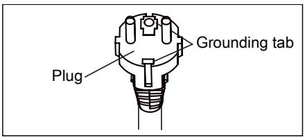
- This appliance must be earthed. This appliance is equipped with a cord having an earth wire. The plug must be plugged into an outlet that is properly installed and earthed.
text_image
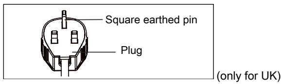
Plug Grounding tab- This appliance is equipped with a cord that has a earthed wire connected to an earthed pin. The plug must be plugged into a socket that is properly installed and earthed. Do not under any circumstances cut or remove the square earthed pin from this plug.
text_image
Square earthed pin Plug (only for UK)1.3 Usage cautions
- Be sure to turn the unit off and disconnect the power supply cord before performing any maintenance or cleaning.
- Do not splash or pour water directly onto the unit. Water can cause electrical shock or equipment damage.
- Drainage should be performed whenever moving the air conditioner (see page 14). If any water remains in the tank, it may spill out while being moved.
- To ensure proper drainage, the drainage hose must have no kinks and must not be elevated during dehumidification mode. If not, the drained water may spill out into the room.
- The temperature around the drainage hose must not be below freezing point when used. Drained water may freeze inside the hose, causing water inside the unit to overflow into the room.
- Do not block the exhaust air outlet with obstacles. Cooling performance may be reduced or stop completely.
- Provide a residual current device (ROD) in order to protect against electric shock in accordance with British Standard and Wiring Rules.
- Exposure to direct airflow for an extended period of time could be hazardous to your health. Do not expose occupants, pets, or plants to direct airflow for extended periods of time.
- Do not use this air conditioner for non-specified special purposes (e.g. preserving precision devices, food, pets, plants, and art objects). Usage in such a manner could harm such property.
2. SAFETY INSTRUCTION
2.1 Notes on Operation
- Allow 3 minutes for the compressor to restart cooling. If you turn the air conditioner off and immediately restart it, allow 3 minutes for the compressor to restart cooling. There is an electronic device in the unit that keeps the compressor turned off for 3 minutes for safety.
- In the event of a power failure during use, allow 3 minutes before restarting the unit. After power is reinstated, restart the air conditioner. If the power was off for less than three minutes, be sure to wait at least three minutes before restarting the unit. if you restart the air conditioner within three minutes, a protective device in the unit may cause the compressor to shut off.
This protective device will prevent cooling for about 5 minutes. Any previous setting will be cancelled and the unit will return to its initial setting.
- Low temperature operation: Is your unit freezing up? Freezing may occur when the unit is set close to 18°C in low ambient temperature conditions, especially at night. In these conditions, a further temperature drop may cause the unit to freeze. Setting the unit to a higher temperature will prevent it from freezing.
- Dehumidification mode increases room temperature. The unit generates heat during dehumidification mode and the room temperature will rise. Warm air will be blown out from the exhaust air outlet, but this is normal and does not indicate a problem with the unit.
- This air conditioner blows the warm air generated by the unit outside the room via the exhaust hose while in cool mode. In the mean time, the same amount of air will enter the room from outside through any openings of the room.
- Do not use means to accelerate the defrosting process or to clean, other than those recommended by the manufacturer.
- The appliance shall be stored in a room without continuously operating ignition sources (for example: open flames, an operating gas appliance or an operating electric heater).
- Do not pierce or burn.
- Appliance should be installed, operated and stored in a room with a floor area larger than 12 m ^2 .
• Compliance with national gas regulations shall be observed. - Keep ventilation openings clear of obstruction.
-
The appliance shall be stored in a well-ventilated area where the room size larger than 12 m ^2 .
-
Any person who is involved with working on or breaking into a refrigerant circuit should hold a current valid certificate from an industry-accredited assessment authority, which authorises their competence to handle refrigerants safely in accordance with an industry recognised assessment specification.
- Servicing shall only be performed as recommended by the equipment manufacturer. Maintenance and repair requiring the assistance of other skilled personnel shall be carried out under the supervision of the person competent in the use of flammable refrigerants.
- This product contains a lithium button/coin cell battery. If a new or used lithium button/coin cell battery is swallowed or enters the body, it can cause severe internal burns and can lead to death in as little as 2 hours. Always completely secure the battery compartment. If the battery compartment does not close securely, stop using the product, remove the batteries, and keep it away from children. If you think batteries might have been swallowed or placed inside any part of the body, seek immediate medical attention.
natural_image
Warning symbol of a flame inside a triangle (no text or numbers)To prevent injury to the user or other people and property damage, the following instructions must be followed. Incorrect operation due to ignoring instructions may cause harm or damage. The seriousness is classified by the following indications:

natural_image
Simple line drawing of an open book with no text or symbols visibleMeanings of symbols used in this manual are shown below:
This symbol indicates never to do this.
This symbol indicates always do this.
2.2 Warning during usage
WARNING!
Warning during usage

WARNING!
This symbol indicates the possibility of death or serious injury.

CAUTION!
This symbol indicates the possibility of injury or damage to property.
| Warning | Meaning |
| Plug in power plug properly | Otherwise, it may cause electric shock or fire due to excess heat generation |
| Do not operate or stop the unit by inserting or pulling out Die power plug | It may cause electric shock or fire due to heat generation |
| Do not damage or use an unspecified power cord | It may cause electric shook or fire. If the power cord is damaged, it must be replaced by the manufacturer or an authorised service centre or a similarly qualified person in order to avoid a hazard |
| Do not modify power cord length or share the outlet with other appliances | It may cause electric shock or fire due to heat generation |
| Do not operate with wet hands or in damp environment | It may cause electric shock |
| Do not direct airflow at room occupants | This could harm your health |
| Always ensure effective earthing | Incorrect earthing may cause electric shock |
| Do not allow water to run into electric parts | It may cause failure of unit or electric shock |
| Always install circuit breaker and a dedicated power circuit | Incorrect installation may cause electric shock |
| Unplug the unit if strange sounds, smell, or smoke comes from it | It may cause fire and electric shock |
| Do not use the socket if it is loose or damaged | It may cause fire and electric shock |
| Do not open the unit during operation | It may cause fire and electric shock |
| Keep firearms away | It may cause fire |
| Do not use the power cord close to heating appliances | It may cause fire and electric shock |
| Do not use the power cord near flammable gas or combustibles, such as gasoline, benzene, thinner, etc. | It may cause an explosion or fire |
| Ventilate room before operating air conditioner if there is a gas leakage from another appliance | It may cause explosion, fire and burns |
| Do not disassemble or modify unit | It may cause failure and electric shock |
| Caution | Meaning |
| When the air filter is to be removed, do not touch the metal parts of the unit | It may cause an injury |
| Do not clean the air conditioner with water | Water may enter the unit and degrade the insulation. It may cause an electric shock |
| Ventilate the room well when used together with a stove, etc. | An oxygen shortage may occur |
| When the unit is to be cleaned, switch off, and turn off the circuit breaker | Do not clean unit when power is on as it may cause fire and electric shock, it may cause an injury |
| Do not place a pet or house plant where it will be exposed to direct air flow | This could injure the pet or plant |
| Do not use for special purposes | Do not use this air conditioner to preserve precision devices, food, pets, plants, and art objects. It may cause deterioration of quality, etc. |
| Stop operation and close the window in storm or cyclone | Operation with windows opened may cause wetting of indoor and soaking of household furniture |
| Hold the plug by the head of the power plug when taking it out | It may cause electric shock and damage |
| Turn off the main power switch when not using the unit for a long time | It may cause failure of product or fire |
| Do not place obstacles around air-inlets or inside of air-outlet | It may cause failure of appliance or accident |
| Always insert the filters securely. Clean filter once every two weeks | Operation without filters may cause failure |
| Do not use strong detergent such as wax or thinner - use a soft cloth | Appearance may be deteriorated due to change of product colour or scratching of its surface |
| Do not place heavy object on the power cord and ensure that the cord is not compressed | There is danger of fire or electric shock |
| Do not drink water drained from air conditioner | It contains contaminants and could make you sick |
| Use caution when unpacking and installing | Sharp edges could cause injury |
| If water enters the unit, turn the unit off at the power outlet and switch off the circuit breaker. Isolate supply by taking the power-plug out and contact a qualified service technician | It could cause electric shock and damage |
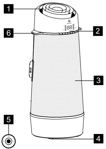
3. UNIT DESCRIPTION
text_image
1 2 3 4 5 61 Room air discharge
2 Control panel
3 Room air inlet
4 Castor
5 Remote control
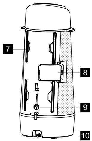
text_image
7 8 9 10Fig. 1
6 Carrying handle (both sides)
7 Filter
8 Exhaust air outlet
9 Drain outlet
10 Bottom tray drain outlet
4. ACCESSORIES INCLUDED
| PARTS | PARTS NAME: | QUANTITY: | |
| 1 | 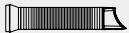 | Exhaust hose | 1 pcs |
| 2 | 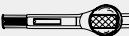 | Window Sliding Kit | 1 pcs |
| 3 |  | Spared Extend Rod | 1 pcs |
| 4 | 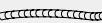 | Drain Hose & Adaptor | 1 pcs |
| 5 | [WWHWM] | 3/8" Screw | 2 pcs |
| 6 | 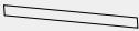 | Decoration film | 1 pcs |
| 7 | 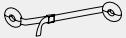 | Fixing Strap | 1 set |
| 8 | [XCHA] | Remote Control | 1 pcs |
Fig. 2
- Check all the accessories are included in the package and please refer to the installation instructions for their usage.
5. INSTALLATION INSTRUCTIONS
5.1 Exhausting hot air
In the COOLING Mode the appliance must be placed close to a window or opening so that the warm exhaust air can be ducted outside. First position unit on a flat floor and make sure there's a minimum of 30cm clearance around the unit, and is within the vicinity of a single circuit outlet power source.
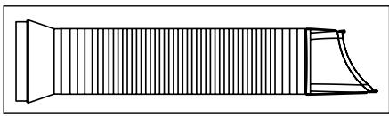
- Extend either side of the hose (Fig. 3).
natural_image
Pure technical line drawing of a mechanical component without any text, numbers, or symbolsFig. 3
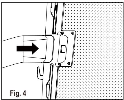
- Slide the adaptor A into the exchange hole of the unit as shown on Fig. 4.
natural_image
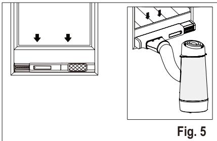
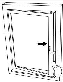
Technical diagram showing a mechanical assembly with an arrow indicating direction, labeled Fig. 4 (no text or symbols on the diagram itself)- Install the window kit on the window and slide the adaptor B into the window slider kit and seal. (Fig. 5 & 6)
natural_image
Diagram showing a device with two arrows pointing to a panel and a labeled cylindrical device (no text or symbols present)
natural_image
Technical diagram showing a door panel and a cylindrical device with directional arrows, labeled Fig. 6 (no text or symbols on the diagram itself)i Window Slider Kit Minimum: 56cm Maximum: 112cm
Refer to “5.2 Installation in a casement window” about how to install the window kit.
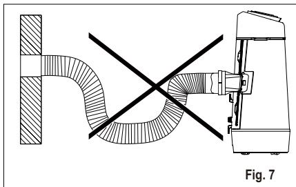
The hose can be extended from its original length of 38cm up to 150cm, but it is the best to keep the length to minimum required. Also make sure that the hose does not have any sharp bends or sags. (Fig. 7)
natural_image
Technical diagram showing a pipe connection with cross-section and mechanical assembly (no text or symbols)5.2 Installation in a casement window
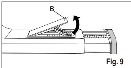
- Open the window sash and lift the locking lever of the window slider kit (Fig. 9)
text_image
B Fig. 9B: Locking lever
- Place the window slider kit on the window. Adjust the length of the window slider kit according to the height of window (Fig. 10).
natural_image
Line drawing of a door frame with an arrow indicating direction (no text or symbols)Fig. 10

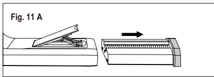
The telescopic rod can be extended, if the window is too high. To do that, first take out the telescopic rod completely (Fig. 11 A). Then align the 3 hooks on the extending rod (sold separately) to the 3 slots on the end of the telescopic rod and slide the 3 hooks into the slots, then press down the extending rod to lock the slots (Fig. 11 B). After that slide the combined telescopic rod back into the window kit (Fig. 11 C).
text_image
Fig. 11 A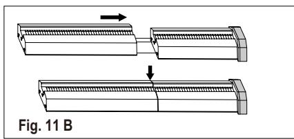
natural_image
Diagram showing two mechanical components with arrows indicating motion, labeled Fig. 11 B (no text or symbols on the diagram itself)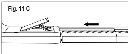
text_image
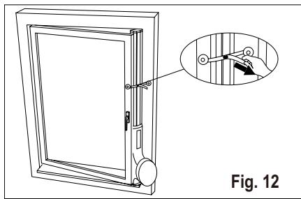
Fig. 11 C- Press back the locking lever to fix the length of the window slider kit, then close the window and pinch the window kit between the window and the window frame, to secure the window kit, peel off the protect film in the back of the tabs of the anchor and attach on the window frame, then fasten the strap (Fig. 12).
natural_image
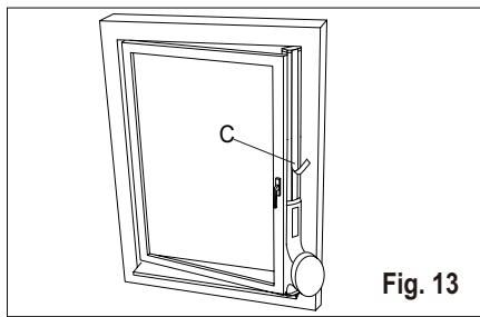
Technical line drawing of a door with an inset showing a hand holding a panel (no text or symbols present)- Cut the decoration film to an appropriate length and stick on the extend rod (Fig. 13).
natural_image
Line drawing of a door frame with labeled component C, no text or symbols presentC: Decoration film
6. AIR CONDITIONER FEATURES
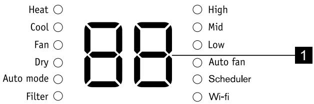
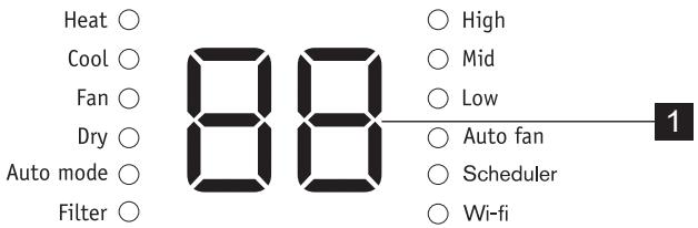
6.1 CONTROL PANEL

text_image
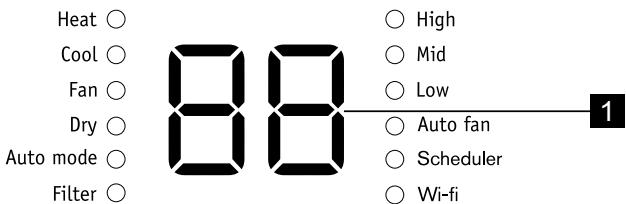
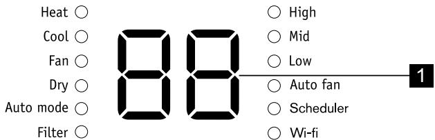
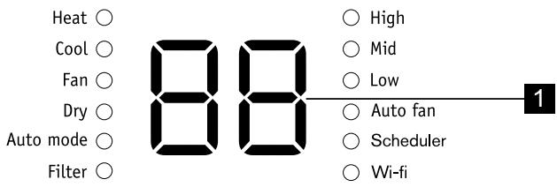
Heat ○ Cool ○ Fan ○ Dry ○ Auto mode ○ Filter ○ 88 ○ High ○ Mid ○ Low ○ Auto fan ○ Scheduler ○ Wi-fi 1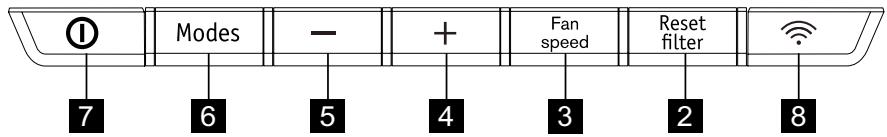
text_image
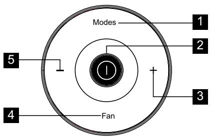
① Modes - + Fan speed Reset filter 7 6 5 4 3 2 81 Displays temperature
2 Filter reset button (hold 3 secs to reset)
3 Sets fan speed
4 Increase temperature
6.2 Remote Control
text_image
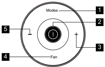
Modes 1 2 3 4 Fan 51 Press to select modes
2 Press to turn on or off unit
3 Press to increase temperature setting
4 Press to select fan speeds
5 Press to decrease temperature setting
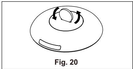
Open the back covers and remove the protecting film to activate the remote control, when use for the first time.
To replace the battery
- Turn over the remote control. In the button of the remote control there is a slot.
5 Decrease temperature
6 Sets mode
7 Turns unit on or off
8 wifi button
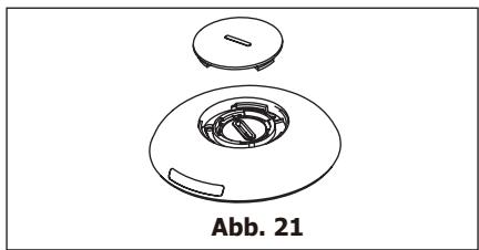
- Use a coin or something like that to rotate the back cover anti-clockwise to open it. (Fig. 20 & 21)
natural_image
Simple line drawing of a dome-shaped object with internal rotation arrows, labeled Fig. 20 (no text or symbols on the diagram itself)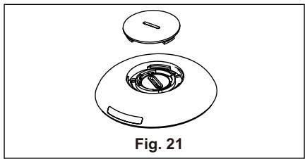
natural_image
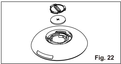
Technical line drawing of a mechanical component with a circular housing and a separate top view, labeled Fig. 21 (no text or symbols on the diagram itself)- Use the same way to open the protecting cover inside and take out the battery. (Fig. 22)
natural_image
Exploded view diagram of a mechanical component, showing internal parts and part outline (no text or symbols)- Replace the battery and reinstall the inside cover and back cover.
Battery Type: RG15D/E-ELL (Rated Voltage: 3VDC)

WARNING!
Please use the battery appropriately
- Chemical Burn Hazard. Keep batteries away from children.
-
Be sure the batteries are inserted properly.
-
Do not use batteries other than the type specified.
- Do not use old batteries with new ones.
- Do not dispose of batteries in fire. Batteries may explode or leak.
- The cells shall be disposed of properly, including keeping them away from children and even used cells may cause injury.
- To prevent damage, remove the batteries when not being used for a long time.
- This device complies with Part 15 of the FCC Rules. Operation is subject to the following two conditions: (1) This device may not cause harmful interference, and (2) this device must accept any interference received, including interference that may cause undesired operation.
7. OPERATING INSTRUCTIONS

Some of the following instructions can only be used by using the Control Panel.
7.1 Usage of the Control Panel
Heating mode (on some models)
In this mode the exhaust adaptor hose MUST be used.
- Press the "Modes" button until the "Heat" indicator is lit.
- Press the “−” & “+” Temp buttons for desired setting.
- Press the "fan speed" button for desired fan speed.
- Connected drain hose. See 7.3 Drainage section.
Cooling mode
In this mode the exhaust adaptor hose MUST be used.
- Press the "Modes" button until the "Cool" indicator lights.
- Press the “−” & “+” Temp buttons for desired setting.
- Press the "Fan speed" button for desired fan speed.

It is not necessary to use the drainage hose in the “cool” mode.
Fan mode
In this mode there is no need to use the exhaust hose or drainage hose.
- Press the "Modes" button until the "Fan" indicator is lit.
- Press the "Fan speed" button to choose the desired fan speed.
- The fan will run at the selected speed and the display will show the room temperature.
Dry mode
In this mode you do not need to use the exhaust adaptor hose, BUT the water collected must be discharged. See 7.3 Drainage Section.
- Press the "Modes" button until the "Dry" indicator is lit.
- The fan will run at low speed and the display will show the room temperature.
- Keep doors & windows closed for best effect.
- Connected drain hose. See Drainage section.
Auto mode
Always have the exhaust hose attached in this mode.
When you set the air conditioner in Auto mode, it will automatically select cooling, heating (inapplicable for cooling only models), or fan only operation depending on what temperature you have selected and the room temperature. The air conditioner will control room temperature automatically round the temperature point set by you.
Under AUTO mode, you can not select the fan speed.
- Press the "Modes" button until the "Auto mode" indicator lights.
After the “Auto mode” is selected the unit will run automatically according to the actual room air temperature.
Check filter feature
- Cleaning the filter.
- Press and hold the "filter" button for 3 seconds to turn off the filter indicator.
Selecting fan speed
You can select the desired fan speed, by pressing the "Fan speed" button. The fan speed will change in the sequence: "Auto Fan", "High", "Mid", "Low".

After choosing the fan speed as "Auto Fan", "High", "Mid" or "Low", the corresponding fan speed indicator light will illuminate. Under Auto and Dry mode, you can not select the fan speed.
DEACTIVATE WIFI MODULE:
The wifi module can be deactivated by holding the “Connect button” and “-” “synchronously 3 seconds. Press the “Connect button” again to activate the wifi module again. It will take about 10 seconds for the module to initiate again.
7.2 Fault code
If the display reads "A5", the room temperature sensor has failed. Contact your Authorized Electrolux Service Centre.

If the display reads "E5", the evaporator temperature sensor has failed. Contact your Authorized Electrolux Service Centre.

If the display reads "E4", the display panel communication has failed. Contact your Authorized Electrolux Service Centre.

If the display reads “P1”, bottom tray is full. Carefully move the unit to a drain location, remove the bottom drain plug and let the water drain away. Restart the machine until the “P1” symbol disappears. If error repeats, call for service.

If the display reads "E7", the indoor motor has failed. Contact your Authorized Electrolux Service Center.

7.3 Drainage
During the Heat and dry mode, you need to connect the drain hose to the drain outlet in the back of the unit to drain the condensate from the unit. Otherwise, the unit may not function normally and display show "P1".
A. Discharge into a drain that is lower than the unit.
B. The unit have a pump to drain the condensate.
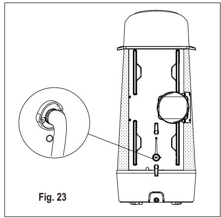
natural_image
Technical line drawing of a device with an inset close-up showing a mechanical component (no text or symbols)If necessary you can extend the drain hose by adapting the drain hose adaptor in the end of the drain hose, then use a 8-9mm hose to extend. (Fig. 24)
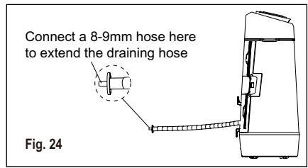
text_image
Connect a 8-9mm hose here to extend the draining hose Fig. 24During cooling mode, please replace the rubber stopper to the hose connector to reach the maximum performance.
7.4 Operation Tips
Now that you have mastered the operating procedure, here are more features in your control that you should become familiar with.
- The “Cool” circuit has an automatic 3 minutes time delayed start if the unit is turned off and on quickly. This prevents overheating of the compressor and possible circuit breaker tripping. The fan will continue to run during this time.
- Temperature can be set between 16°C and 32°C.
- The control is capable of displaying temperature in degrees Fahrenheit or degrees Celsius. To convert from one to the other and back, press and hold the “TEMP” Up (+) and Down (−) buttons together for 3 seconds.
- There is a 2-Second delay for the compressor shutting down when selecting Fan. This is to cover the possibility of having to roll through to select another mode.
- After a power outage, the unit will memorize the last setting and return the unit to the same setting once power is restored.
- Indoor operating temperature range for this product is 16°C to 35°C.
- During normal operation, the unit's display will show room temperature but when the room temperature is over 37°C the display will show "HI".
- After 60 seconds of control inactivity the display and indicator lights will turn off. Press any button on the control panel or remote control and the display will resume.
8. CARE & CLEANING
Clean your air conditioner regularly to keep it looking new.
8.1 Air filter cleaning
Be sure to unplug the unit before cleaning to prevent shock or fire hazards. Enter the context of your task here (optional).
- Grasp the filters tab and pull off the 4 filters on the back of the unit one by one.
- Wash the filter using liquid dishwashing detergent and warm water. Rinse filter thoroughly. Gently shake excess water from the filter. Or, instead of washing you may vacuum the filter clean.

Be sure filter is thoroughly dry before replacing.
- Put back the filter after the filter is dry.
8.2 Cabinet Cleaning
Be sure to unplug the air conditioner to prevent shock or fire hazard.
9. TROUBLE SHOOTING
Before calling for service, review this list. It may save you time and expense. This list includes common occurrences that are not the result of defective workmanship or materials in this appliance.
Air conditioner will not operate.
- Wall plug disconnected. Push plug firmly into wall outlet.
- House fuse blown or circuit breaker tripped. Replace fuse with time delay type or reset circuit breaker.
- Control is OFF. Turn Control ON and set to desired setting.
- P1 appears in the display window. Drain water as described in 7.3 Drainage Section.
- Room Temperature lower than the set temperature (Cool Mode). Reset the temperature.
The cabinet and front may be dusted with an oil-free cloth or washed with a cloth dampened in a solution of warm water and mild liquid dishwashing detergent. Rinse thoroughly and wipe dry.

Caution when cleaning the unit.
- Never use harsh cleaners, wax or polish on the cabinet front.
- Be sure to wring excess water from the cloth before wiping around the controls. Excess water in or around the controls may cause damage to the air conditioner.
8.3 Winter Storage
If you plan to store the appliance during the winter, cover it with plastic or return it to its carton box.
Air from unit does not feel cold enough.
- Room temperature below 16°C. Cooling may not occur until room temperature rises above 16°C.
- Reset to a lower temperature.
- Compressor shut-off by changing modes. Wait approximately 3 minutes and listen for compressor to restart when set in the COOL mode.
Air conditioner cooling, but room is too warm - NO ice forming on cooling coil behind decorative front.
- Outdoor temperature below 16°C. To defrost the coil, set Fan mode.
- Air filter may be dirty. Clean filter. Refer to 8. Care and Cleaning section. To defrost, set to Fan mode.
- Temperature is set too low for nighttime cooling. To defrost the coil,
set to Fan mode. Then, set temperature to a higher setting.
- Exhaust duct not connected or blocked. See 5.1 Exhausting hot air Section.
Air conditioner cooling, but room is too warm - ice forming on cooling coil behind decorative front.
- Dirty air filter - air restricted. Clean air filter. Refer to 8. Care and Cleaning section.
- Temperature is set too high. Set temperature to a lower setting.
• Air directional louvers positioned improperly. Position louvers for better air distribution. -
Front of unit is blocked by drapes, blinds, furniture, etc. - restricts air distribution. Clear blockage in front of unit.
-
Doors, windows, registers, etc. open - cool air escapes. Close doors, windows, registers, etc.
- Unit recently turned on in hot room. Allow additional time to remove “stored heat” from walls, ceiling, floor and furniture.
Air conditioner turns on and off rapidly.
- Dirty air filter - air restricted. Clean air filter.
- Outside temperature extremely hot. Set FAN speed to a faster setting to bring air through cooling coils more frequently.
Room too cold.
- Set temperature too low. Increase set temperature.
10. ADDITIONAL INFORMATION
Transport of equipment containing flammable refrigerants
See transport regulations.
Marking of equipment using signs
See local regulations.
Disposal of equipment using flammable refrigerants
See national regulations.
Storage of equipment/appliances
The storage of equipment should be in accordance with the manufacturer's instructions.
Storage of packed (unsold) equipment
Storage package protection should be constructed such that mechanical damage to the equipment inside the package will not cause a leak of the refrigerant charge. The maximum number of pieces of equipment permitted to be stored together will be determined by local regulations.
Information on servicing
- Checks to the area. Prior to beginning work on systems containing flammable refrigerants, safety checks are necessary to ensure that the risk of ignition is minimised. For repair to
the refrigerating system, the following precautions shall be complied with prior to conducting work on the system.
- Work procedure. Work shall be undertaken under a controlled procedure so as to minimise the risk of a flammable gas or vapour being present while the work is being performed.
-
General work area. All maintenance staff and others working in the local area shall be instructed on the nature of work being carried out. Work in confined spaces shall be avoided. The area around the workspace shall be sectioned off. Ensure that the conditions within the area have been made safe by control of flammable material.
-
Checking for presence of refrigerant. The area shall be checked with an appropriate refrigerant detector prior to and during work, to ensure the technician is aware of potentially flammable atmospheres. Ensure that the leak detection equipment being used is suitable for use with flammable refrigerants, i.e. nonsparking, adequately sealed or intrinsically safe.
-
Presence of fire extinguisher. If any hot work is to be conducted on the refrigeration equipment or any associated parts, appropriate fire extinguishing equipment shall be available to hand. Have a dry powder or CO2 fire extinguisher adjacent to the charging area.
-
No ignition sources. No person carrying out work in relation to a refrigeration system which involves exposing any pipe work that contains or has contained flammable refrigerant shall use any sources of ignition in such a manner that it may lead to the risk of fire or explosion. All possible ignition sources, including cigarette smoking, should be kept sufficiently far away from the site of installation, repairing, removing and disposal, during which flammable refrigerant can possibly be released to the surrounding space. Prior to work taking place, the area around the equipment is to be surveyed to make sure that there are no flammable hazards or ignition risks. "No Smoking" signs shall be displayed.
-
Ventilated area. Ensure that the area is in the open or that it is adequately ventilated before breaking into the system or conducting any hot work. A degree of ventilation shall continue during the period that the work is carried out. The ventilation should safely disperse any released refrigerant and preferably expel it externally into the atmosphere.
-
Checks to the refrigeration equipment. Where electrical components are being changed, they shall be fit for the purpose and to the correct specification. At all times the manufacturer's maintenance and service guidelines shall be followed. If in doubt consult the manufacturer's technical department for assistance. The following checks shall be applied to installations using flammable refrigerants:
-
The charge size is in accordance with the room size within which the refrigerant containing parts are installed;
-
The ventilation machinery and outlets are operating adequately and are not obstructed;
-
If an indirect refrigerating circuit is being used, the secondary circuit shall be checked for the presence of refrigerant;
- Marking to the equipment continues to be visible and legible. Markings and signs that are illegible shall be corrected;
-
Refrigeration pipe or components are installed in a position where they are unlikely to be exposed to any substance which may corrode refrigerant containing components, unless the components are constructed of materials which are inherently resistant to being corroded or are suitably protected against being so corroded.
-
Checks to electrical devices. Repair and maintenance to electrical components shall include initial safety checks and component inspection procedures. If a fault exists that could compromise safety, then no electrical supply shall be connected to the circuit until it is satisfactorily dealt with. If the fault cannot be corrected immediately but it is necessary to continue operation, an adequate temporary solution shall be used. This shall be reported to the owner of the equipment so all parties are advised.
Initial safety checks shall include:
- That capacitors are discharged: this shall be done in a safe manner to avoid possibility of sparking;
- That there no live electrical components and wiring are exposed while charging, recovering or purging the system;
- That there is continuity of earth bonding.
Repairs to sealed components
-
During repairs to sealed components, all electrical supplies shall be disconnected from the equipment being worked upon prior to any removal of sealed covers, etc. If it is absolutely necessary to have an electrical supply to equipment during servicing, then a permanently operating form of leak detection shall be located at the most critical point to warn of a potentially hazardous situation.
-
Particular attention shall be paid to the following to ensure that by working on electrical components, the casing is not altered in such a way that the level of protection is affected. This shall include damage to cables, excessive number of connections, terminals not made to original specification, damage to seals, incorrect fitting of glands, etc. Ensure that apparatus is mounted securely. Ensure that seals or sealing materials have not degraded such that they no longer serve the purpose of preventing the ingress of flammable atmospheres. Replacement parts shall be in accordance with the manufacturer's specifications.
NOTE: The use of silicon sealant may inhibit the effectiveness of some types of leak detection equipment. Intrinsically safe components do not have to be isolated prior to working on them.
Repair to intrinsically safe components
Do not apply any permanent inductive or capacitance loads to the circuit without ensuring that this will not exceed the permissible voltage and current permitted for the equipment in use.
Intrinsically safe components are the only types that can be worked on while live in the presence of a flammable atmosphere. The test apparatus shall be at the correct rating. Replace components only with parts specified by the manufacturer.
Other parts may result in the ignition of refrigerant in the atmosphere from a leak.
Cabling
Check that cabling will not be subject to wear, corrosion, excessive pressure, vibration, sharp edges or any other adverse environmental effects. The check shall also take into account the effects of aging or continual vibration from sources such as compressors or fans.
Detection of flammable refrigerants
Under no circumstances shall potential sources of ignition be used in the searching for or detection of refrigerant leaks. A halide torch (or any other detector using a naked flame) shall not be used.
Leak detection methods
The following leak detection methods are deemed acceptable for systems containing flammable refrigerants. Electronic leak detectors shall be used to detect flammable refrigerants, but the sensitivity may not be adequate, or may need re-calibration. (Detection equipment shall be calibrated in a refrigerant-free area.) Ensure that the detector is not a potential source of ignition and is suitable for the refrigerant used. Leak detection equipment shall be set at a percentage of the LFL of the refrigerant and shall be calibrated to the refrigerant employed and the appropriate percentage of gas (25 % maximum) is confirmed.
Leak detection fluids are suitable for use with most refrigerants but the use of detergents containing chlorine shall be avoided as the chlorine may react with the refrigerant and corrode the copper pipe-work.
If a leak is suspected, all naked flames shall be removed/ extinguished. If a leakage of refrigerant is found which requires brazing, all of the refrigerant shall be recovered from the system, or isolated (by means of shut off valves) in a part of the system remote from the leak. Oxygen free nitrogen (OFN) shall then be purged through the system both before and during the brazing process.
Removal and evacuation
When breaking into the refrigerant circuit to make repairs – or for any other purpose – conventional procedures shall be used. However, it is important that best practice is followed since flammability is a consideration. The following procedure shall be adhered to:
- Remove refrigerant;
- Purge the circuit with inert gas;
- Evacuate;
- Purge again with inert gas;
- Open the circuit by cutting or brazing.
The refrigerant charge shall be recovered into the correct recovery cylinders. The system shall be “flushed” with OFN to render the unit safe. This process may need to be repeated several times. Compressed air or oxygen shall not be used for this task. Flushing shall be achieved by breaking the vacuum in the
system with OFN and continuing to fill until the working pressure is achieved, then venting to atmosphere, and finally pulling down to a vacuum. This process shall be repeated until no refrigerant is within the system. When the final OFN charge is used, the system shall be vented down to atmospheric pressure to enable work to take place. This operation is absolutely vital if brazing operations on the pipework are to take place.
Ensure that the outlet for the vacuum pump is not close to any ignition sources and there is ventilation available.
Charging procedures
In addition to conventional charging procedures, the following requirements shall be followed.
- Ensure that contamination of different refrigerants does not occur when using charging equipment. Hoses or lines shall be as short as possible to minimise the amount of refrigerant contained in them.
- Cylinders shall be kept upright.
- Ensure that the refrigeration system is earthed prior to charging the system with refrigerant.
- Label the system when charging is complete (if not already).
- Extreme care shall be taken not to overfill the refrigeration system.
Prior to recharging the system it shall be pressure tested with OFN. The system shall be leak tested on completion of charging but prior to commissioning. A follow up leak test shall be carried out prior to leaving the site.
Decommissioning
Before carrying out this procedure, it is essential that the technician is completely familiar with the equipment and all its detail. It is recommended good practice that all refrigerants are recovered safely. Prior to the task being carried out, an oil and refrigerant sample shall be taken in case analysis is required prior to re-use of reclaimed refrigerant. It is essential that electrical power is available before the task is commenced.
- Become familiar with the equipment and its operation.
- Isolate system electrically.
- Before attempting the procedure ensure that:
- Mechanical handling equipment is available, if required, for handling refrigerant cylinders;
- All personal protective equipment is available and being used correctly;
- The recovery process is supervised at all times by a competent person;
-
Recovery equipment and cylinders conform to the appropriate standards.
-
Pump down refrigerant system, if possible.
-
If a vacuum is not possible, make a manifold so that refrigerant can be removed from various parts of the system.
-
Make sure that cylinder is situated on the scales before recovery takes place.
-
Start the recovery machine and operate in accordance with manufacturer's instructions.
-
Do not overfill cylinders. (No more than 80% volume liquid charge).
-
Do not exceed the maximum working pressure of the cylinder, even temporarily.
-
When the cylinders have been filled correctly and the process completed, make sure that the cylinders and the equipment are removed from site promptly and all isolation valves on the equipment are closed off.
-
Recovered refrigerant shall not be charged into another refrigeration system unless it has been cleaned and checked.
Labelling
Equipment shall be labelled stating that it has been de-commissioned and emptied of refrigerant. The label shall be dated and signed. Ensure that there are labels on the equipment stating the equipment contains flammable refrigerant.
Recovery
When removing refrigerant from a system, either for servicing or decommissioning, it is recommended good practice that all refrigerants are removed safely.
When transferring refrigerant into cylinders, ensure that only appropriate refrigerant recovery cylinders are employed. Ensure that the correct number of cylinders for holding the total system charge is available. All cylinders to be used are designated for the recovered refrigerant and labelled for that refrigerant (i.e. special cylinders for the recovery of refrigerant). Cylinders shall be complete with pressure relief valve and associated shut-off valves in good working order. Empty recovery cylinders are evacuated and, if possible, cooled before recovery occurs.
The recovery equipment shall be in good working order with a set of instructions concerning the equipment that is at hand and shall be suitable for the recovery of flammable refrigerants. In addition, a set of calibrated weighing scales shall be available and in good working order. Hoses shall be complete with leak-free disconnect couplings and in good condition. Before using the recovery machine, check that it is in satisfactory working order, has been properly maintained and that any associated electrical components are sealed to prevent ignition in the event of a refrigerant release. Consult manufacturer if in doubt.
The recovered refrigerant shall be returned to the refrigerant supplier in the correct recovery cylinder, and the relevant Waste Transfer Note arranged. Do not mix refrigerants in recovery units and especially not in cylinders. If compressors or compressor oils are to be removed, ensure that they have been evacuated to an acceptable level to make certain that flammable refrigerant does not remain within the lubricant. The evacuation process shall be carried out prior to returning the compressor to the suppliers. Only electric heating to the compressor body shall be employed to accelerate this process. When oil is drained from a system, it shall be carried out safely.

WARNING!
- Do not use means to accelerate the defrosting process or to clean, other than those recommended by the manufacturer.
- The appliance shall be stored in a room without continuously operating, ignition sources (for example: open flames, an operating gas appliance or an operating electric heater).
- Do not pierce or burn.
- Be aware that the refrigerants may not contain an odour.
- Appliance should be installed, operated and stored in a room with a floor area larger than 12 m ^2 .
- The appliance shall be stored so as to prevent mechanical damage from occurring a warning that the appliance shall be stored in a well-ventilated area where the room size corresponds to the room area as specified for operation.
- Any person who is involved with working on or breaking into a refrigerant circuit should hold a current valid certificate from an industry-accredited assessment authority, which authorises their competence to handle refrigerants safely in accordance with an industry recognised assessment specification.
- Servicing shall only be performed as recommended by the equipment manufacturer. Maintenance and repair requiring the assistance of other skilled personnel shall be carried out under the supervision of the person competent in the use of flammable refrigerants.
11. ENVIRONMENTAL CONCERNS
Recycle the materials with the symbol. Put the packaging in applicable containers to recycle it. Help protect the environment and human health and to recycle waste of electrical and electronic
appliances. Do not dispose appliances marked with the symbol ☒ with the household waste. Return the product to your local recycling facility or contact your municipal office.
OBSAH
- BEZPEČNOSTNÍ INFORMACE 25
- BEZPEČNOSTNÍ POKYNY 28
- POPIS ZAŘÍZENÍ 32
- OBSAŽENÉ PŘÍSLUŠENSTVÍ 32
- POKYNY K INSTALACI 33
- VLASTNOSTI KLIMATIZAČNÍHO ZAŘÍZENÍ 35
- PROVOZNÍ POKYNY 36
- ČIŠTĚNÍ A ÚDRŽBA 39
- ODSTRAŇOVÁNÍ ZÁVAD 39
- DODATEČNÉ INFORMACE 40
- POZNÁMKY K OCHRANĚ ŽIVOTNÍHO PROSTŘEDÍ ..... 44
MYSLÍME NA VÁS
natural_image
Warning symbol of a flame inside a triangle (no text or numbers)natural_image
Simple line drawing of an open book with no text or symbols visiblenatural_image
Pure technical line drawing of a mechanical component without any text, numbers, or symbolsObr. 3
natural_image
Line drawing of a door with an arrow indicating direction, labeled 'Obr. 10' (no other text or symbols)text_image
Obr. 11 A
text_image
Obr. 11 B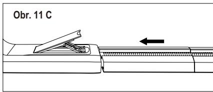
text_image
Obr. 11 Cnatural_image
Technical line drawing of a door with an inset showing a hand holding a clip, labeled 'Obr. 12' (no text or symbols on the diagram itself)natural_image
Line drawing of a door frame with labeled component C, no text or symbols presentC: Ozdobná páska
6. VLASTNOSTI KLIMATIZAČNÍHO ZAŘÍZENÍ
6.1 OVLÁDACÍ PANEL
text_image
Heat ○ Cool ○ Fan ○ Dry ○ Auto mode ○ Filter ○ 88 ○ High ○ Mid ○ Low ○ Auto fan ○ Scheduler ○ Wi-fi 1
text_image
① Modes - + Fan speed Reset filter 7 6 5 4 3 2 8natural_image
Simple line drawing of a circular object with internal rotation arrows, labeled 'Obr. 20' below (no text or symbols on the object itself)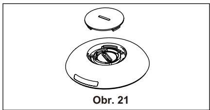
natural_image
Technical line drawing of a mechanical component with a circular housing and a small inset component, labeled 'Obr. 21' (no other text or symbols)natural_image
Exploded view diagram of a mechanical component with no text or symbolsnatural_image
Warning symbol of a flame inside a triangle (no text or numbers)
natural_image
Simple line drawing of an open book with no text or symbols visible5.1 Exhausting hot air
natural_image
Pure technical line drawing of a mechanical component without any text, numbers, or symbolsFig. 3
natural_image
Diagram of a mechanical device with an arrow indicating direction, labeled Fig. 4 (no text or symbols on the diagram itself)natural_image
Diagram showing a refrigerator with two downward arrows and a close-up of the device handle (no text or symbols present)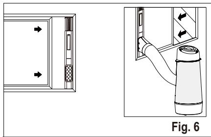
natural_image
Diagram showing a door panel and a hand inserting a cylindrical device into a cabinet, with directional arrows indicating movement (no text or symbols present)Vinduesskydesæt Minimum: 56 cm Maximum: 112 cm
Se under "5.2 Installation i vindue" om anvendelse af vindueskit.
natural_image
Technical diagram showing a pipe connection with no visible text or symbols5.2 Installation i vindue
natural_image
Line drawing of a door with an arrow indicating direction, labeled Fig. 10 (no text or symbols on the diagram itself)natural_image
Technical illustration of two mechanical components with arrows indicating motion, labeled Fig. 11 B (no text or symbols on the diagram itself)
text_image
Fig. 11 Cnatural_image
Technical line drawing of a door with an inset showing a hand holding a clip (no text or symbols present)natural_image
Line drawing of a door frame with labeled component C, no text or symbols presentC: Pyntefolie
6. AIRCONDITIONERS FUNKTIONER
6.1 BETJENINGSPANEL
text_image
Heat ○ Cool ○ Fan ○ Dry ○ Auto mode ○ Filter ○ 88 ○ High ○ Mid ○ Low ○ Auto fan ○ Scheduler ○ Wi-fi 1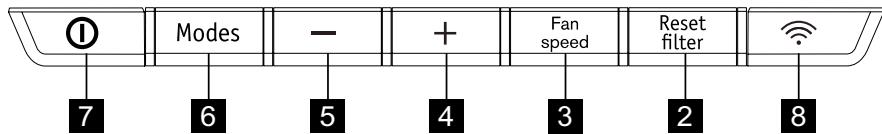
text_image
① Modes - + Fan speed Reset filter 7 6 5 4 3 2 8natural_image
Simple line drawing of a hat-like object with a circular top and side handle, labeled Fig. 20 (no text or symbols on the diagram itself)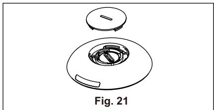
natural_image
Technical line drawing of a mechanical component, labeled Fig. 21 (no text or symbols on the diagram itself)natural_image
Exploded view diagram of a mechanical component, showing internal parts and part outline (no text or symbols)natural_image
Technical line drawing of a mechanical device with an inset close-up view labeled Fig. 23 (no text or symbols on the diagram itself)natural_image
Warning symbol of a flame inside a triangle (no text or numbers)natural_image
Simple line drawing of an open book with no text or symbols visiblenatural_image
Technical line drawing of a mechanical component with ribbed top and tapered end (no text or symbols)Kuva 3
natural_image
Line drawing of a door with an arrow indicating direction, labeled 'Kuva 10' (no other text or symbols)
text_image
① Modes - + Fan speed Reset filter 7 6 5 4 3 2 8natural_image
Technical line drawing of a Kuva 21 component with circular housing and handle (no text or symbols on the diagram itself)natural_image
Exploded view diagram of a Kuva 22 device showing internal components (no text or symbols)natural_image
Warning symbol of a flame inside a triangle (no text or numbers)natural_image
Simple line drawing of an open book with no text or symbols visiblenatural_image
Pure technical line drawing of a mechanical component without any text, numbers, or symbolsFig. 3
natural_image
Technical diagram showing a mechanical assembly with an arrow indicating direction, labeled 'Fig. 4' (no text or symbols on the diagram itself)natural_image
Technical diagram showing a door panel and a cylindrical device with directional arrows, labeled Fig. 6 (no text or symbols on the diagram itself)natural_image
Technical diagram showing a pipe connection with no visible text or symbolsnatural_image
Line drawing of a door frame with an arrow indicating direction (no text or symbols)Fig. 10
natural_image
Technical illustration of two mechanical components with arrows indicating motion, labeled Fig. 11 B (no text or symbols on the diagram itself)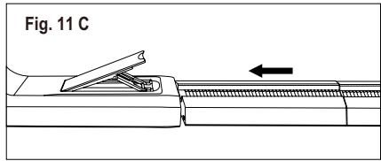
text_image
Fig. 11 Cnatural_image
Technical line drawing of a door with an inset showing a hand holding a switch (no text or symbols present)natural_image
Line drawing of a door with labeled component C, no text or symbols presentC : Film décoratif
6. CARACTÉRISTIQUES DU CLIMATISEUR
6.1 BANDEAU DE COMMANDE

text_image
Heat ○ Cool ○ Fan ○ Dry ○ Auto mode ○ Filter ○ 88 ○ High ○ Mid ○ Low ○ Auto fan ○ Scheduler ○ Wi-fi 1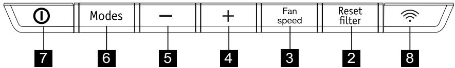
text_image
① Modes - + Fan speed Reset filter 7 6 5 4 3 2 8natural_image
Simple line drawing of a circular object with internal rotation arrows, labeled Fig. 20 (no text or symbols on the diagram itself)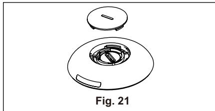
natural_image
Technical line drawing of a mechanical component with a circular base and a lid, labeled Fig. 21 (no text or symbols on the diagram itself)natural_image
Exploded view diagram of a mechanical component, showing internal parts and a cross symbol (no text or labels)natural_image
Technical line drawing of a device with an inset close-up showing a mechanical component (no text or symbols)natural_image
Warning symbol of a flame inside a triangle (no text or numbers)natural_image
Simple line drawing of an open book with no text or symbols visible4. TARTOZÉKOK A CSOMAGBAN
natural_image
Pure technical line drawing of a mechanical component without any text, numbers, or symbols3. ábra
natural_image
Line drawing of a door with an arrow indicating direction (no text or symbols)- ábra
text_image
① Modes - + Fan speed Reset filter 7 6 5 4 3 2 8natural_image
Technical line drawing of a circular mechanical component with a labeled section '21. ábra' (no other text or symbols)natural_image
Exploded view diagram of a mechanical component with labeled part '22. ábra' (no other text or symbols)natural_image
Warning symbol of a flame inside a triangle (no text or numbers)natural_image
Simple line drawing of an open book with no text or symbols visiblenatural_image
Pure technical line drawing of a mechanical component without any text, numbers, or symbolsFig. 3
natural_image
Technical diagram showing a mechanical assembly with an arrow indicating direction, labeled 'Fig. 4' (no text or symbols on the diagram itself)natural_image
Diagram showing a refrigerator with two arrows indicating leftward movement and a gas collection bottle labeled Fig. 5 (no text or symbols on the diagram itself)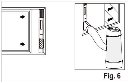
natural_image
Technical diagram showing a door panel and a cylindrical device with directional arrows, labeled Fig. 6 (no text or symbols on the diagram itself)natural_image
Technical diagram showing a pipe connection with no visible text or symbolsnatural_image
Line drawing of a door frame with an arrow indicating direction (no text or symbols)Fig. 10
natural_image
Diagram showing two mechanical components with arrows indicating motion, labeled Fig. 11 B (no text or symbols on the diagram itself)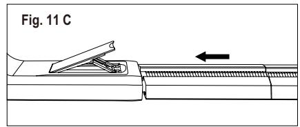
text_image
Fig. 11 Cnatural_image
Line drawing of a door with an inset showing a hand holding a tool, labeled Fig. 12 (no text or symbols on the diagram itself)natural_image
Line drawing of a door frame with labeled component C, shown in Fig. 13 (no text or symbols beyond label)C: Film decorazione
6. CARATTERISTICHE DEL CONDIZIONATORE D'ARIA
6.1 QUADRO COMANDI
text_image
Heat ○ Cool ○ Fan ○ Dry ○ Auto mode ○ Filter ○ 88 ○ High ○ Mid ○ Low ○ Auto fan ○ Scheduler ○ Wi-fi 1
text_image
① Modes - + Fan speed Reset filter 7 6 5 4 3 2 8natural_image
Simple line drawing of a circular object with internal rotation arrows, labeled Fig. 20 (no text or symbols on the object itself)
natural_image
Technical line drawing of a mechanical component, labeled Fig. 21 (no text or symbols on the diagram itself)natural_image
Exploded view diagram of a mechanical component, showing internal parts and a cross symbol (no text or labels)natural_image
Technical line drawing of a device with an inset close-up showing a mechanical component (no text or symbols)natural_image
Warning symbol of a flame inside a triangle (no text or numbers)natural_image
Simple line drawing of an open book with no text or symbols visiblenatural_image
Technical line drawing of a mechanical component with grooves and a tapered end (no text or symbols)Figur 3
natural_image
Technical diagram showing a mechanical assembly with an arrow indicating direction, labeled Fig. 4 (no text or symbols on the diagram itself)natural_image
Diagram showing a device with ports and a water dispenser, labeled as Fig. 5 (no text or symbols on the diagram itself)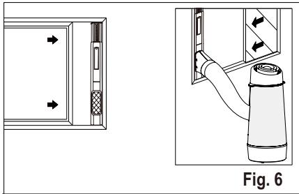
natural_image
Technical diagram showing a door panel and a gas cylinder assembly with directional arrows (no text or symbols)Glidestykkesett for vindu Minimum: 56 cm Maks: 112 cm
natural_image
Technical diagram showing a pipe connection with no visible text or symbolsnatural_image
Line drawing of a door frame with an arrow indicating direction (no text or symbols)Fig. 10
natural_image
Technical illustration of two mechanical components with arrows indicating motion, labeled Fig. 11 B (no text or symbols on the diagram itself)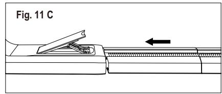
text_image
Fig. 11 Cnatural_image
Technical line drawing of a door with an inset showing a hand holding a tool, labeled Fig. 12 (no text or symbols on the diagram itself)natural_image
Line drawing of a door frame with labeled component 'C', no text or symbols presentC: Dekorasjonsfilm
6. LUFTKJ∅LER FUNKSJONER
6.1 KONTROLLPANEL

text_image
Heat ○ Cool ○ Fan ○ Dry ○ Auto mode ○ Filter ○ 88 ○ High ○ Mid ○ Low ○ Auto fan ○ Scheduler ○ Wi-fi 1
text_image
① Modes - + Fan speed Reset filter 7 6 5 4 3 2 81 Viser temperatur
2 Tilbakestillingsknapp for filter (hold inne i 3 sekunder for å tilbakestille)
3 Stiller inn viftehastighet
4 ∅k temperaturen
5 Reduser temperaturen
6 Velger modus
7 Slår enheten av eller på
8 wifi-knapp
6.2 Fjernkontroll
text_image
Modes 1 2 3 4 Fan 5natural_image
Simple line drawing of a circular object with internal rotation arrows, labeled Fig. 20 (no text or symbols on the diagram itself)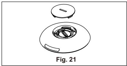
natural_image
Technical line drawing of a mechanical component with a circular housing and a separate top view, labeled Fig. 21 (no text or symbols on the diagram itself)natural_image
Exploded view diagram of a mechanical component, showing internal parts and a cross symbol (no text or labels)natural_image
Technical line drawing of a mechanical device with an inset close-up view labeled Fig. 23 (no text or symbols on the diagram itself)natural_image
Warning symbol of a flame inside a triangle (no text or numbers)natural_image
Simple line drawing of an open book with no text or symbols visiblenatural_image
Pure technical line drawing of a mechanical component without any text, numbers, or symbolsRys. 3
natural_image
Technical diagram showing a door opening and a spray bottle assembly (no text or symbols)natural_image
Line drawing of a door with an arrow indicating direction (no text or symbols)Rys. 10
natural_image
Line drawing of a door with an inset showing a hand holding a switch, labeled 'Rys. 12' (no text or symbols on the diagram itself)natural_image
Line drawing of a door frame with labeled component C, no text or symbols present6. FUNKCJE KLIMATYZATORA
6.1 PANELU STEROWANIA
other
| Category | Value | |---|---| | Heat | ○ | | Cool | ○ | | Fan | ○ | | Dry | ○ | | Auto mode | ○ | | Filter | ○ | ○ High ○ Mid ○ Low ○ Auto fan ○ Scheduler ○ Wi-fi 1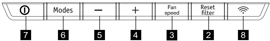
text_image
① Modes - + Fan speed Reset filter 7 6 5 4 3 2 8natural_image
Simple line drawing of a circular object with internal rotation arrows, labeled 'Rys. 20' below (no text or symbols on the object itself)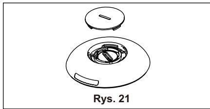
natural_image
Technical line drawing of a mechanical component with a circular base and a lid, labeled 'Rys. 21' (no other text or symbols)natural_image
Exploded view diagram of a mechanical component with no text or symbolstext_image
Square earthed pin Stechernatural_image
Warning symbol of a flame inside a triangle (no text or numbers)
natural_image
Simple line drawing of an open book with no text or symbols visible4. ACCESORII INCLUSE
natural_image
Technical line drawing of a mechanical component with ribbed top and tapered end (no text or symbols)Fig. 3
natural_image
Technical diagram showing a mechanical assembly with an arrow indicating direction, labeled 'Fig. 4' (no text or symbols on the diagram itself)natural_image
Diagram showing a door panel with two arrows pointing to a device, and a close-up of a thermosier bottle labeled Fig. 5 (no text or symbols on the diagram itself)
natural_image
Technical diagram showing a door panel and a cylindrical device with directional arrows, labeled Fig. 6 (no text or symbols on the diagram itself)Kit de culisare a ferestre i Minim: 56 cm Maxim: 112 cm
natural_image
Technical diagram showing a pipe connection with no visible text or symbols, labeled as Fig. 7 (no text or symbols on the diagram itself)natural_image
Line drawing of a door frame with an arrow indicating direction (no text or symbols)Fig. 10
natural_image
Technical illustration of two mechanical components with arrows indicating assembly or movement, labeled Fig. 11 B (no text or symbols on the diagram itself)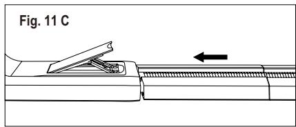
text_image
Fig. 11 Cnatural_image
Technical line drawing of a door with an inset showing a hand holding a switch (no text or symbols present)natural_image
Line drawing of a door with labeled component C, shown as Figure 13 (no text or symbols on the diagram itself)C: Folie decorativă
6. CARACTERISTICILE APARATULUI DE CLIMATIZARE
6.1 PANOU DE COMANDĂ

text_image
Heat ○ Cool ○ Fan ○ Dry ○ Auto mode ○ Filter ○ 88 ○ High ○ Mid ○ Low ○ Auto fan ○ Scheduler ○ Wi-fi 1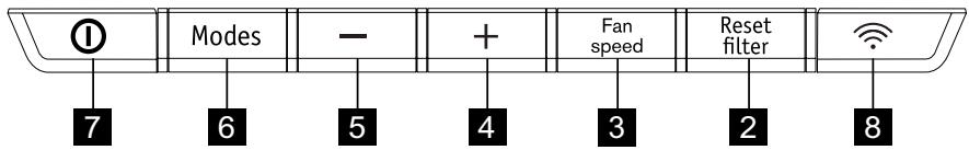
text_image
Modes - + Fan speed Reset filter 7 6 5 4 3 2 8natural_image
Simple line drawing of a circular object with internal rotation arrows, labeled Fig. 20 (no text or symbols on the diagram itself)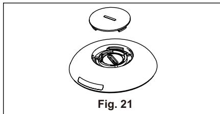
natural_image
Technical line drawing of a mechanical component, labeled Fig. 21, showing a circular housing with internal components and a lid (no text or symbols beyond label)natural_image
Exploded view diagram of a mechanical component, showing internal parts and part outline (no text or symbols)natural_image
Technical line drawing of a device with an inset close-up showing internal components (no text or symbols)natural_image
Warning symbol of a flame inside a triangle (no text or numbers)natural_image
Simple line drawing of an open book with no text or symbols visiblenatural_image
Simple line drawing of a cylindrical object with vertical grooves and a tapered end (no text or symbols)Obr. 3
natural_image
Line drawing of a door with an arrow indicating leftward motion, labeled 'Obr. 10' (no other text or symbols)text_image
Obr. 11 A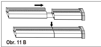
text_image
Obr. 11 B
text_image
Obr. 11 Cnatural_image
Line drawing of a door frame with labeled component C, no text or symbols presentC: Dekoračná fólia
6. FUNKCIE KLIMATIZÁCIE
6.1 OVLÁDACÍ PANEL

text_image
Heat ○ Cool ○ Fan ○ Dry ○ Auto mode ○ Filter ○ 88 ○ High ○ Mid ○ Low ○ Auto fan ○ Scheduler ○ Wi-fi 1
text_image
① Modes - + Fan speed Reset filter 7 6 5 4 3 2 8natural_image
Simple line drawing of a circular object with internal curved arrows and a small protrusion, labeled 'Obr. 20' below (no text or symbols on the diagram itself)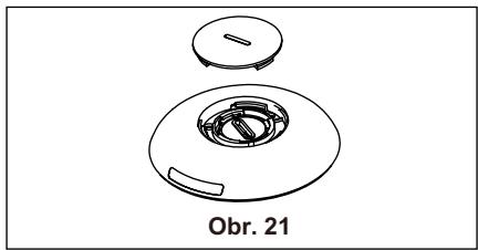
natural_image
Technical line drawing of a circular mechanical component with a central housing and a lid, labeled 'Obr. 21' (no other text or symbols)natural_image
Exploded view diagram of a mechanical component with no text or symbolsnatural_image
Warning symbol of a flame inside a triangle (no text or numbers)
natural_image
Simple line drawing of an open book with no text or symbols visiblenatural_image
Pure technical line drawing of a mechanical component without any text, numbers, or symbolsFig. 3
natural_image
Technical diagram showing a mechanical assembly with an arrow indicating direction, labeled 'Fig. 4' (no text or symbols on the diagram itself)natural_image
Diagram showing a device with two arrows pointing to the left panel and a close-up of a cylindrical device labeled Fig. 5 (no text or symbols on the device itself)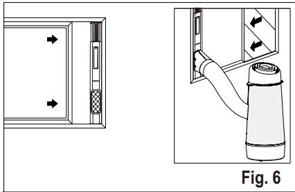
natural_image
Technical diagram showing a door panel and a cylindrical device with directional arrows, labeled Fig. 6 (no text or symbols on the diagram itself)natural_image
Technical diagram showing a pipe connection with no text or symbols, labeled as Fig. 7 (no readable text or symbols)natural_image
Line drawing of a door frame with an arrow indicating direction (no text or symbols)Fig. 10

natural_image
Technical line drawing of a door with an inset showing a hand holding a switch (no text or symbols present)natural_image
Line drawing of a door frame with labeled component 'C', no text or symbols presentC: Dekorationsfilm
6. LUFTKONDITIONERING, FUNKTIONER
6.1 KONTROLLPANEL

text_image
Heat ○ Cool ○ Fan ○ Dry ○ Auto mode ○ Filter ○ 88 ○ High ○ Mid ○ Low ○ Auto fan ○ Scheduler ○ Wi-fi 1
text_image
① Modes - + Fan speed Reset filter 7 6 5 4 3 2 8natural_image
Simple line drawing of a circular object with internal curved arrows, labeled Fig. 20 (no text or symbols on the diagram itself)
natural_image
Technical line drawing of a mechanical component with a circular housing and a lid, labeled Fig. 21 (no text or symbols on the diagram itself)natural_image
Exploded view diagram of a mechanical component, showing internal parts and a central housing (no text or symbols)natural_image
Technical line drawing of a device with an inset close-up showing a mechanical component (no text or symbols)natural_image
Warning symbol of a flame inside a triangle (no text or numbers)natural_image
Simple line icon of an open book (no text or symbols)natural_image
Technical line drawing of a mechanical component with ribbed top and tapered end (no text or symbols)Abb. 3
natural_image
Line drawing of a 3D door with an arrow indicating left side, labeled 'Abb. 10' (no other text or symbols)natural_image
Technical line drawing of a door with an inset showing a hand holding a handle (no text or symbols present)natural_image
Line drawing of a door frame with labeled component 'C' and label 'Abb. 13' (no other text or symbols)C: Dekorfolie
6. FUNKTIONEN DES KLIMAGERÄTS
6.1 BEDIENFELD
line
| Condition | Value | |---|---| | Heat | ○ | | Cool | ○ | | Fan | ○ | | Dry | ○ | | Auto mode | ○ | | Filter | ○ | | High | ○ | | Mid | ○ | | Low | ○ | | Auto fan | ○ | | Scheduler | ○ | | Wi-fi | ○ |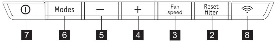
text_image
① Modes - + Fan speed Reset filter 7 6 5 4 3 2 8natural_image
Simple line drawing of a circular object with a knob and curved arrows, labeled Abb. 20 (no text or symbols on the object itself)