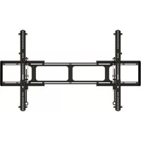
VP1 - TV wall mount SANUS - Free user manual and instructions
Find the device manual for free VP1 SANUS in PDF.
User questions about VP1 SANUS
0 question about this device. Answer the ones you know or ask your own.
Ask a new question about this device
Download the instructions for your TV wall mount in PDF format for free! Find your manual VP1 - SANUS and take your electronic device back in hand. On this page are published all the documents necessary for the use of your device. VP1 by SANUS.
USER MANUAL VP1 SANUS
Europe, Middle East, and Africa: +31 40 2324700 • europe.sanus@milestone.com
Asia Pacific: 86 755 8996 9226·sanus.ap@milestone.com
sanus.com
English
Page 4
Page 18
Deutsch
Seite 20
Espanol
Pagina 22
Portugués
Pagina 24
Nederland
Pageina 26
Italiano
Pageina 28
Eληνικά
i a30
Norsk
Side 32
Dansk
Side 34
Svenska
Sidan 36
Pycckn
Ctp. 38
polski
Strona 40
Česky
Strana 42
Türkçe
Sayfa 44
日本語
46一
中文
第48页
| English Wood ceiling joists Solives de plafond en bois Holzdeckenträge Espanol Vigas de madera Portugues Vigas de teto de madeira Nederland Houten plafondbalken Italiano Travi del soffitto in legno ÉAùnuýá Δokoi ðúlvínc opoúçá Norsk Trebjelker i taket Dansk Loftsbjælker af træ Svenska Takbjällkar av trä Pýsský Bákanie depèvēn Horó noToJOKa polski Drewniane belki stropowe Çesly D'revěné stropné trámy Türke Ahşap tavan kirişleri 日本語 木製の野縁 中文 木吊顶龙骨 | Tools required Outils nécessaires Benötigte Werkzeuge Herramientos necessities Ferramentas necessities Benodiged gereedschap Strumenti richiesti Atraitoúμενα εργαλεία Verktyg som behövs Heōxbodmnbé Инструменты Wymagane naręźdía Požadované nástroje Gereken Aletler | CAUTION ATTENTION VORSICHT PRECAUCÍN ATENÇÃO LET OP ATTENUZIONE ApoLOXH OBSI FORSIGTIG FÖRSIKTIGT ΠΡΕДΥΝΡΕχΙΝΗΝΕ ΠΡΕДΥΝΡΕχΙΝΗΝΕ PRZESTROGA VYSTRAHA | WARNING: This product contains small items that could be a choking hazard. Ce produit contient de petites piées qui peuvent représentier un risque d'étouffement. Dieses Produkt enthält petite Teile, die zum Erstickungstod führen können. Este produit contiene piezas poucoeras que, si fuesen tragadas, podriani producir asfixia. Este produit contém itsens pequenos que podem offérer risco de sufocamento. Dit product bevat keine onderden die stikkingsgevaar{kunnen opleveren. Questo prodotto comprende elementi di piccole dimensioni che potrebbero causare il suffocamento. To prooió autó περιλαβάνει μκρá αυτέίμενα πού μμορείνα αστοτέλδουν κίνδυν πινμόu. Dette produit ineholder smà elementer som kan utgjøre kvelefare. Dette produit ineholder smà dele, som kan forårsage kvælning, hvis de bliver slugt. Den har produit ineholder smà delar som kan utgöra kvävningsrisk. Виздени捶ь мелкines有很大差别, которные могут ссть пrichinión уduшения рпни поадани в дьхатьnetsуг. Produkt zawiera male elementy, ktoré moga grozić zakrztuszeniem. Tento vyrobek obsahujé malé součástky, které hrozi rizikem zadušeni. Bu ürün, boğulma tehlikesine neden olabilecek kúçuk parçalar icermektedir. 本製品には小さい部品が付属.Hereリ、室息の危険性のはんだ。 此产品包含可能带来窒息危险的小组件。 | Repeat Step Répétez l'étape Wiederholen Sie den Schritt Repita este paso Repita a etapa Herhaal stap Ripetere l'opération Enaúáβéte to βñμa Etnaúáβéte to βñμa |
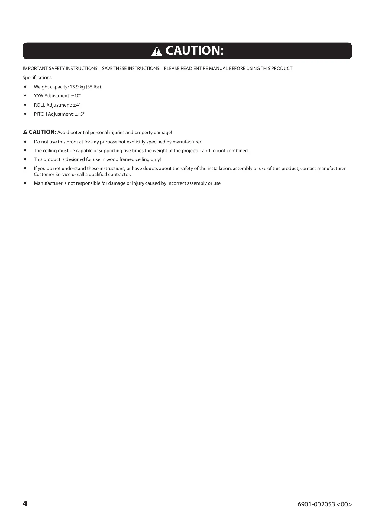
CAUTION:
IMPORTANT SAFETY INSTRUCTIONS – SAVE THESE INSTRUCTIONS – PLEASE READ ENTIRE MANUAL BEFORE USING THIS PRODUCT
Specifications
Weight capacity: 15.9kg (35 lbs)
YAW Adjustment: ± 10^
ROLL Adjustment: ± 4^
PITCH Adjustment: ± 15^
CAUTION: Avoid potential personal injuries and property damage!
Do not use this product for any purpose not explicitly specified by manufacturer.
The ceiling must be capable of supporting five times the weight of the projector and mount combined.
This product is designed for use in wood framed ceiling only!
If you do not understand these instructions, or have doubts about the safety of the installation, assembly or use of this product, contact manufacturer Customer Service or call a qualified contractor.
Manufacturer is not responsible for damage or injury caused by incorrect assembly or use.
Supplied Parts and Hardware
Before starting assembly, verify all parts are included and undamaged. If any parts are missing or damaged, do not return the damaged item to your dealer; contact Customer Service. Never use damaged parts!
NOTE: Not all hardware included will be used.
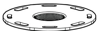
[01] x 1
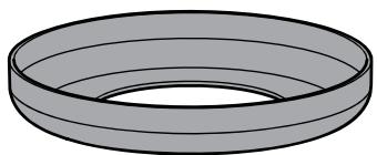
[02] x 1
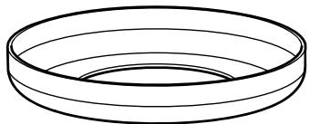
[03] x 1
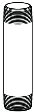
[04] x 1
[05] x 1
[06] x 1
[07] x 1
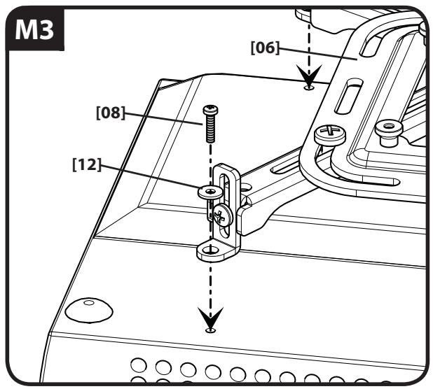
M3 x 12mm
[08] x 4
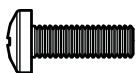
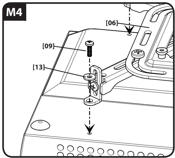
M4x12mm
[09] x 4
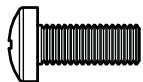
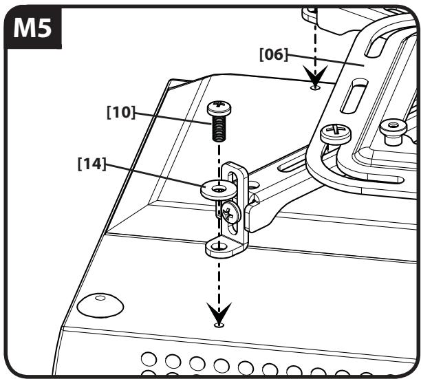
M5 x 12mm
[10] x 4
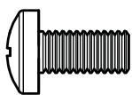
M6 x 12mm
[11] x 4

M3
[12] x 4

M4
[13] x 4
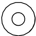
M5
[14] x 4
M6
[15] x 4
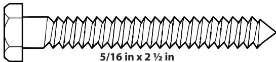
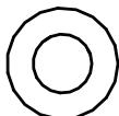
[17] x 2
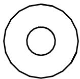
[18] x 2
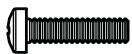
10-24 x 1/4 in
[19] x 1
INSTALL PROJECTOR BRACKET
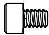
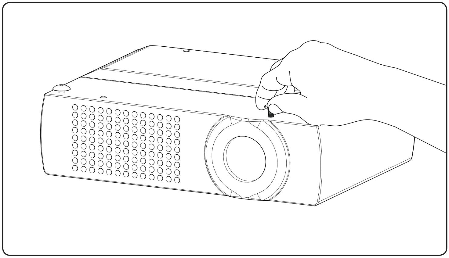
Before you begin, hand thread screws into the threaded inserts on the projector to determine the correct screw diameter (M3, M4, M5, or M6).
1-1
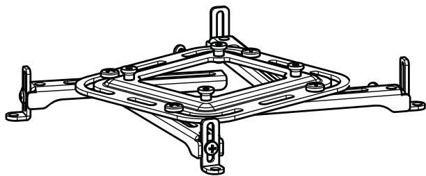
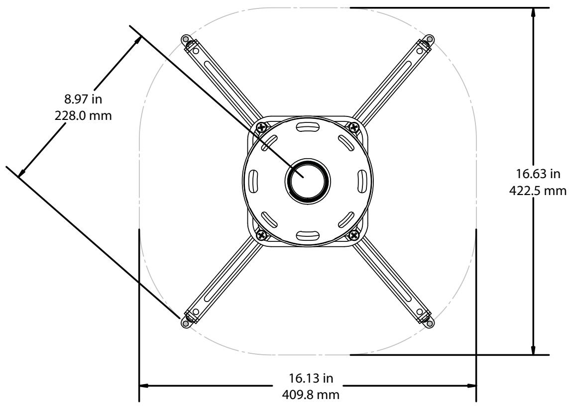
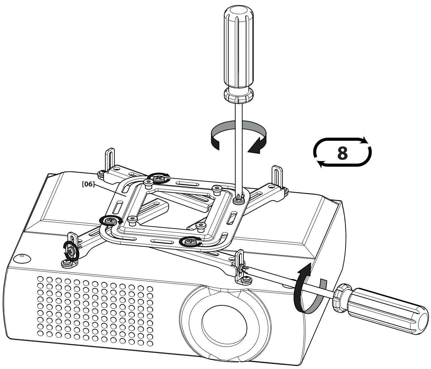
The VP1 bracket arms are adjustable to accommodate projectors with hole patterns as large as 16.63 inches (422.5 mm) square.
Loosen the arm positioning screws to adjust the bracket to fit your projector.
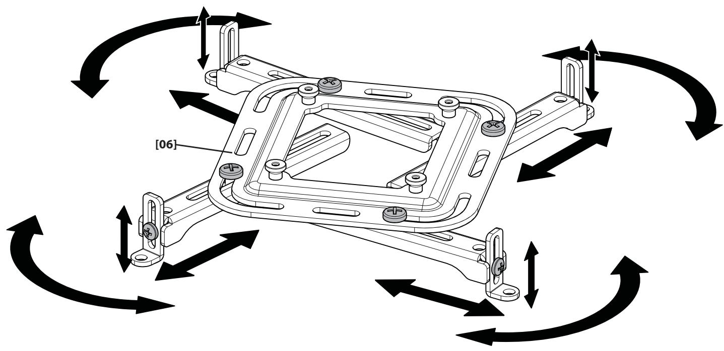
Adjust the arms of the mounting bracket [06] to fit the hole pattern and surface of your projector. Attach the bracket [06] to the projector using the appropriate screws and washers.
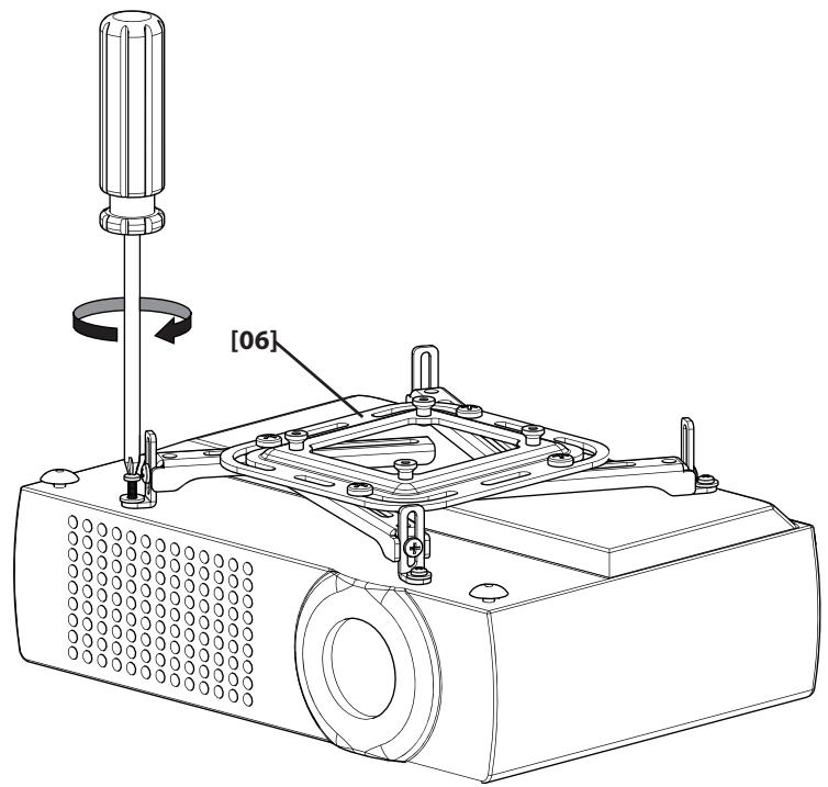
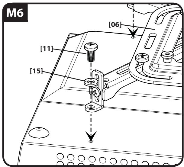
When the bracket [06] is mounted, tighten the arm positioning screws securely.

CAUTION:
CEILING MOUNTING
CAUTION: Improper use could reduce the holding power of the lag bolt. To avoid potential injuries or property damage:
Do not over-tighten the lag bolts [17].
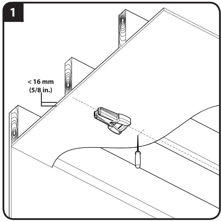
Any material covering the ceiling must not exceed 16 mm (5/8 in.).
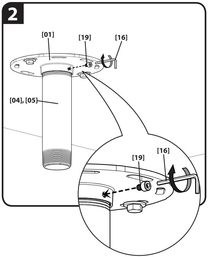
Pilot holes MUST be drilled to a depth of 75mm (3 in.), using a 5.5mm (7/32 in.) diameter drill bit.
English
Wood Joist Ceiling Mounting
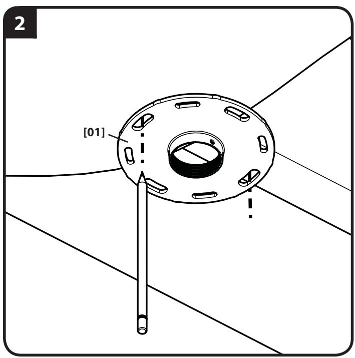
- Locate joist. Verify the center of the joist with an awl or thin nail or use an edge to edge joist finder.
- Align the ceiling plate [01] and mark the hole locations.
- Drill pilot holes as illustrated.
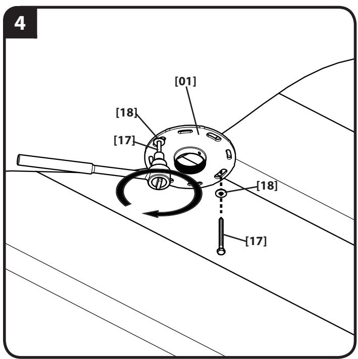
- Tighten the lag bolts [17] only until the washers [18] are pulled firmly against the ceiling plate [01].
English
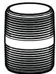
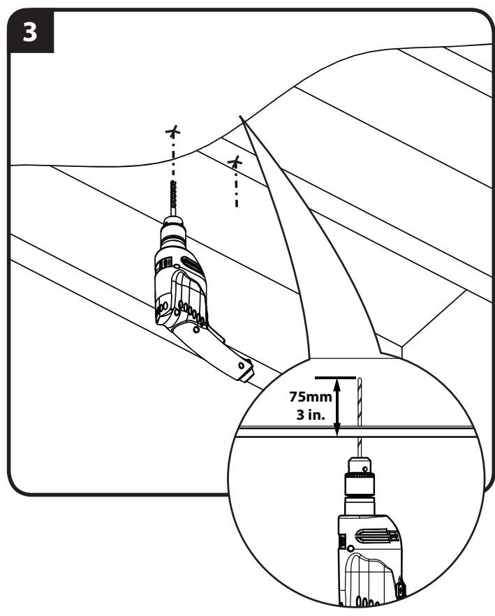
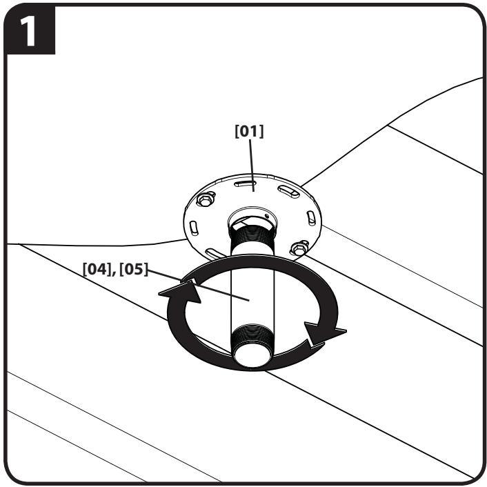
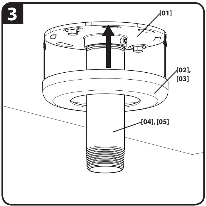
Hanging Tube and Plate Cover
- Carefully screw threaded tube [04] or [05] into ceiling plate until tube either contacts the ceiling or is fully threaded into plate [01].
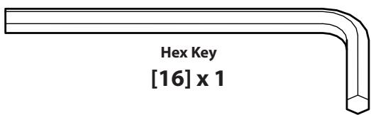
- Insert tube locking screw [19] into plate [01] and tighten securely with hex key [16].
CAUTION:DO NOT OVERTIGHTEN!
Overtightening of set screw can damage threads on pipe.
3. Press plate cover [02] or [03] onto ceiling plate [01].
English
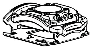
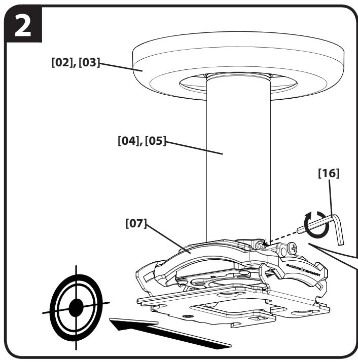
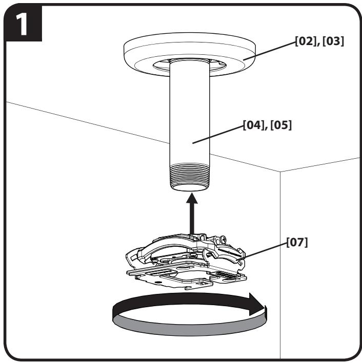
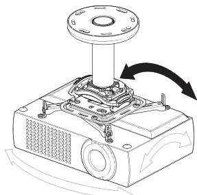
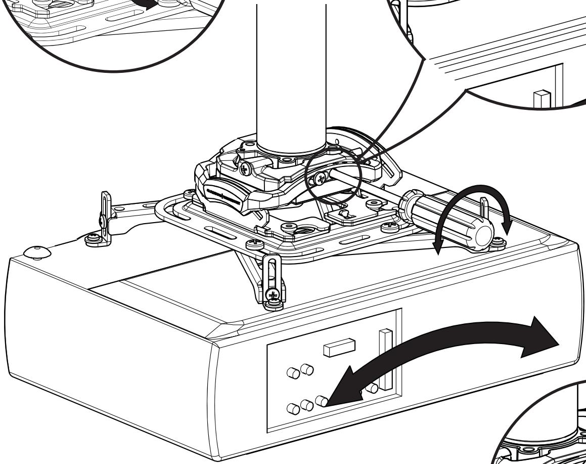
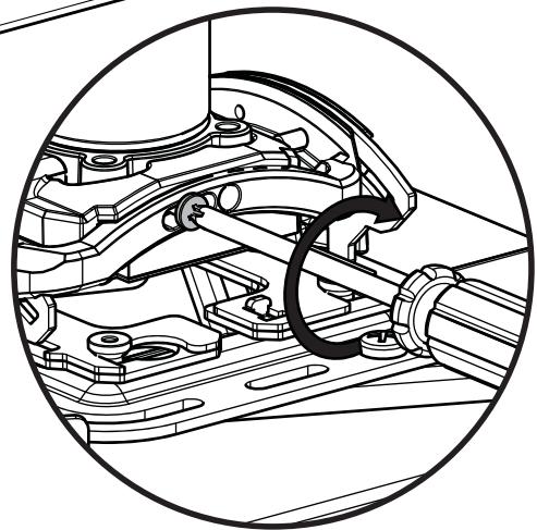
Install Swivel Mount
- Carefully screw swivel mount [07] onto threaded tube [04] or [05] until hand tight.
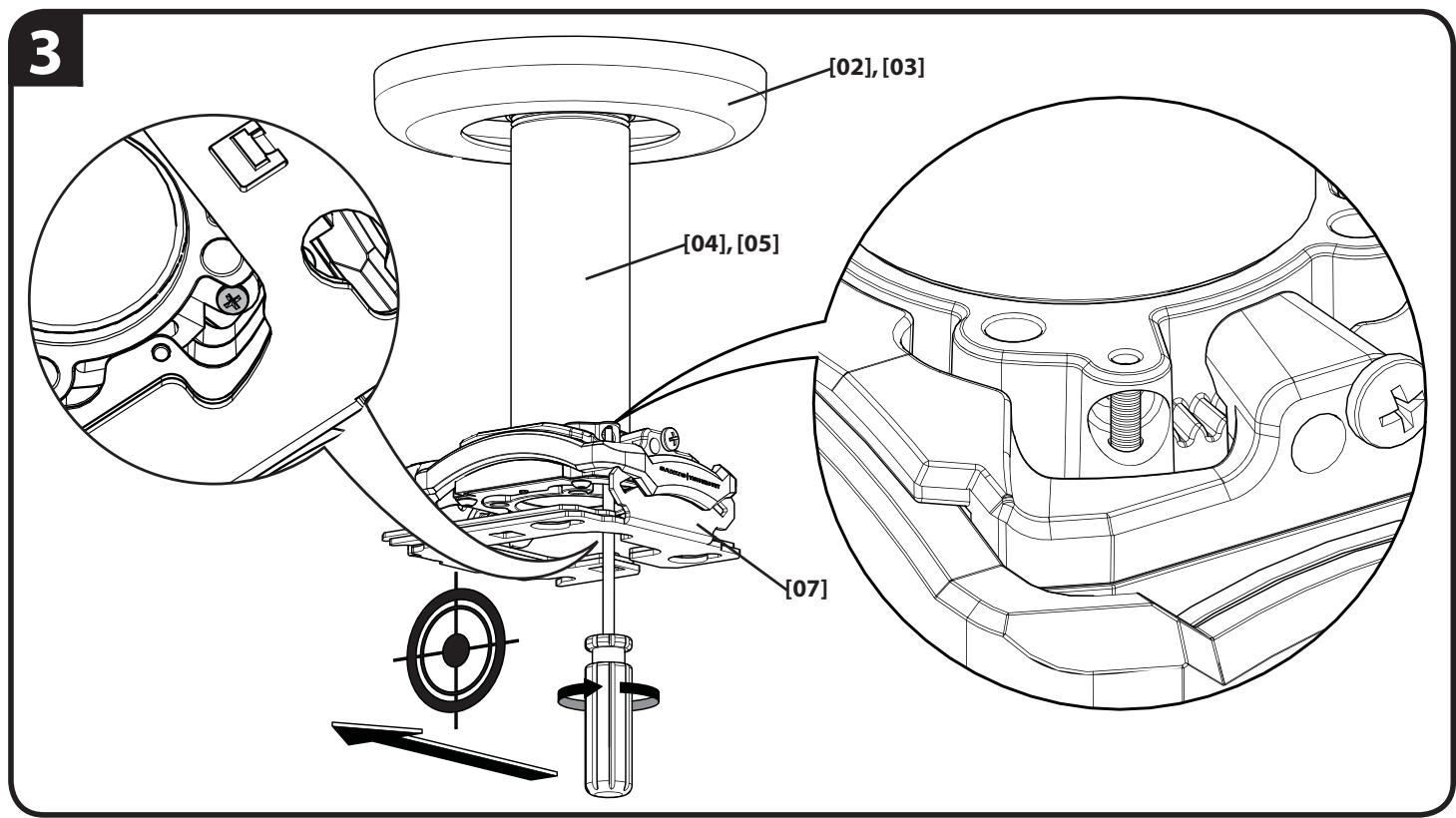
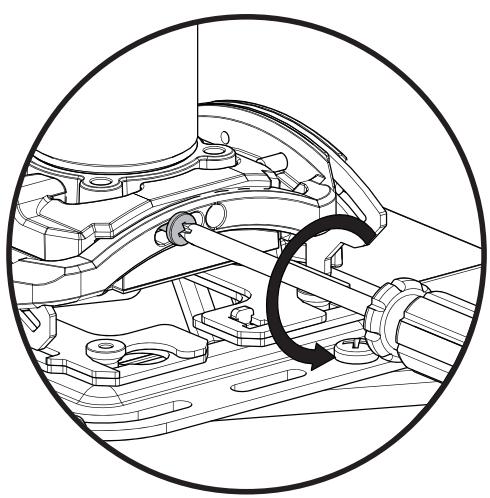
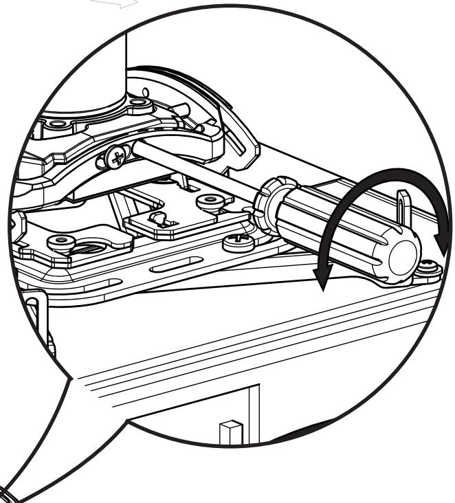
- Position the front of the swivel mount [07] towards the target area then carefully tighten the set screw with hex key [16].
CAUTION:DO NOT OVERTIGHTEN!
Overtightening of set screw can damage threads on pipe.
- Turn security screw using a Phillips screwdriver until set screw cannot be seen through access hole in swivel mount [07].
English
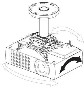
WARNING: IMPROPER INSTALLATION CAN LEAD TO PROJECTOR FALLING, RESULTING IN PERSONAL INJURY OR DAMAGE TO EQUIPMENT.
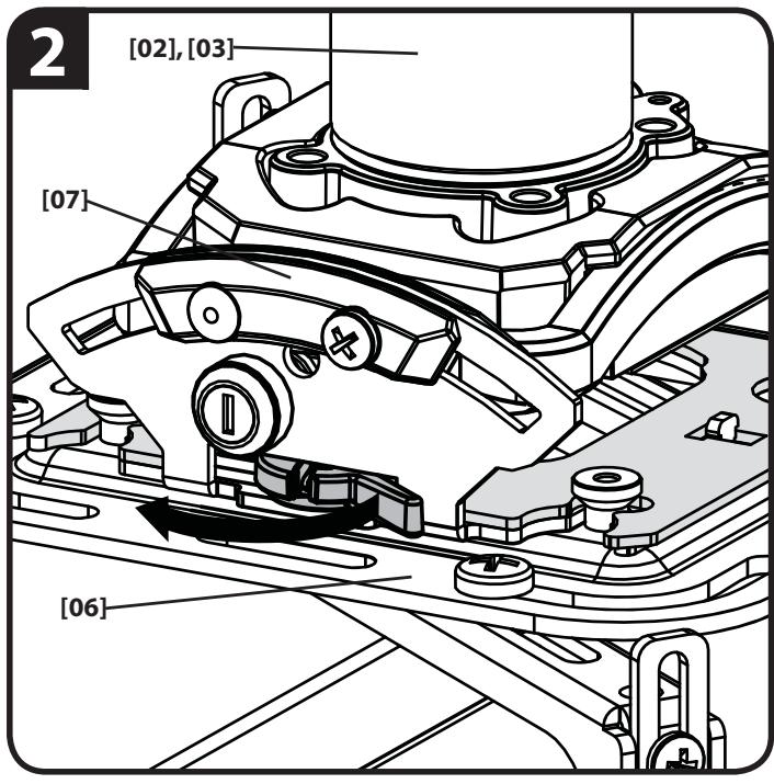
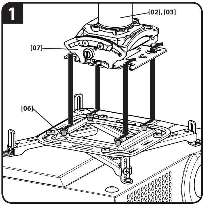
- Attach projector bracket [06] (with projector) onto swivel mount [07] making certain mounting slots in swivel mount [07] slide under thumb screws and that screws are seated in the back of slots.
- Move locking lever to "Locked" position.
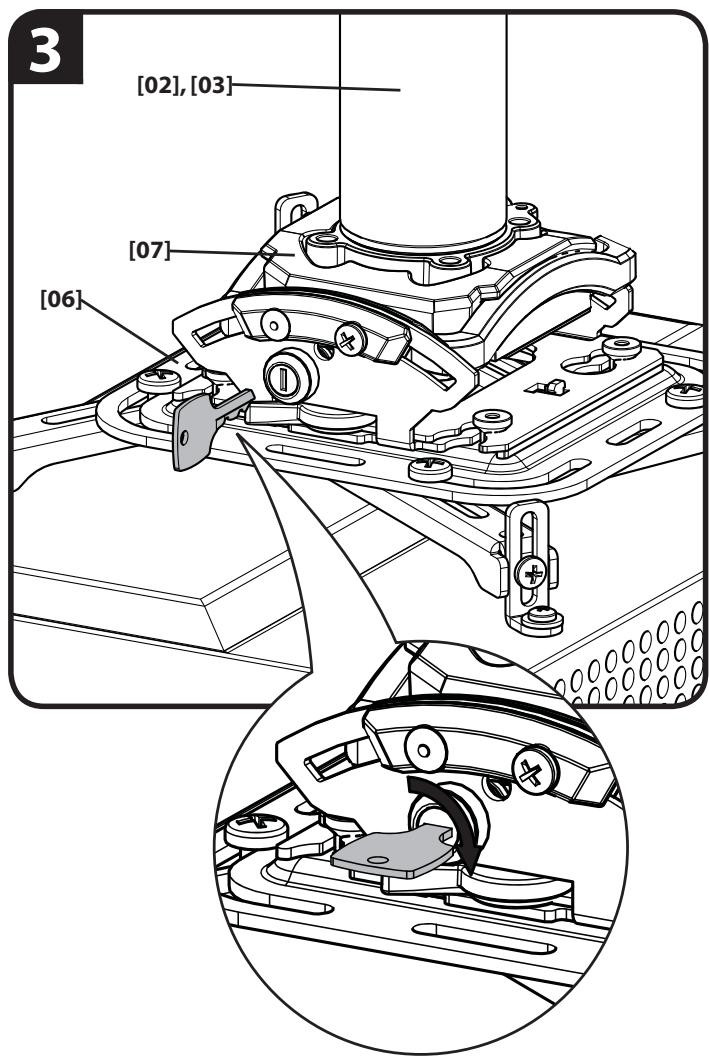
- Insert key into lock and turn to secure projector and projector bracket [06] to swivel mount [07].
English
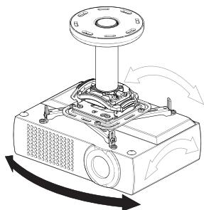
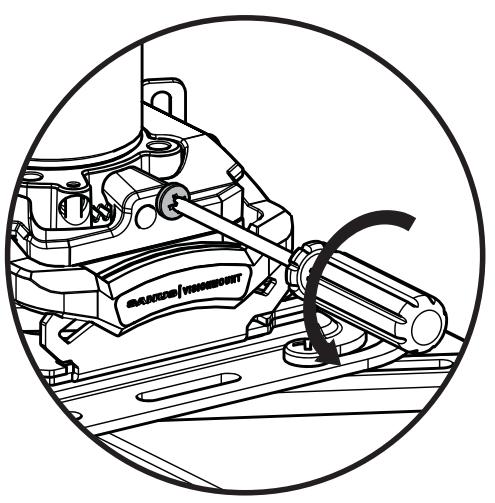
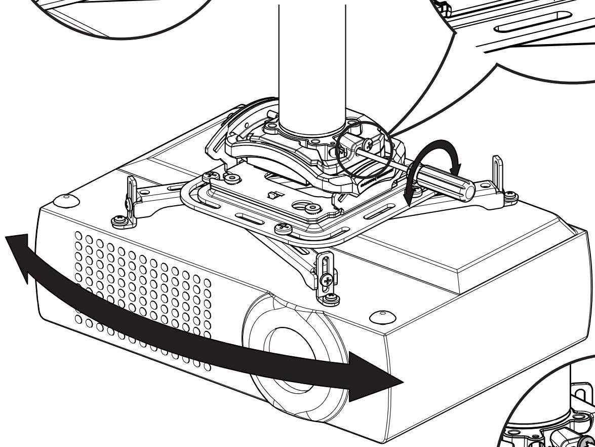
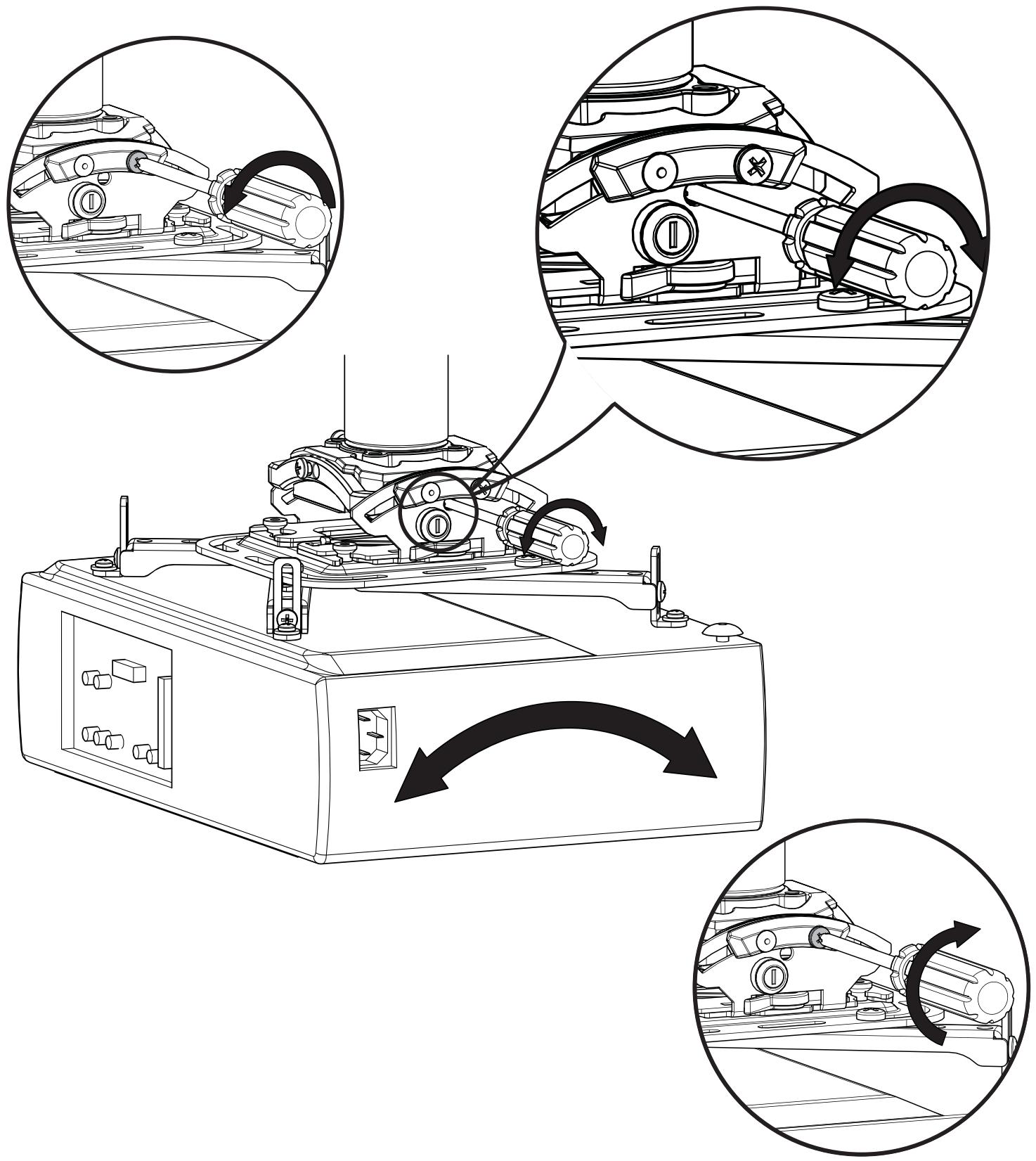
ADJUSTMENTS
YAW Adjustment
Loosen YAW adjustment locking screw using a #2 Phillips screwdriver. Turn YAW micro-adjustment screw right or left using a #2 Phillips screwdriver until image is properly aligned on target. Tighten YAW adjustment locking screw using a #2 Phillips screwdriver.
English
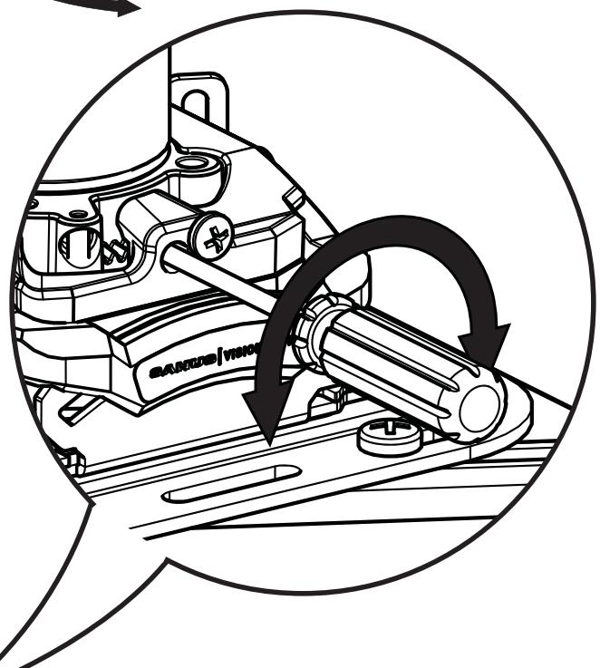
ADJUSTMENTS
ROLL Adjustment
Loosen ROLL adjustment locking screw using a #2 Phillips screwdriver. Turn ROLL micro-adjustment screw right or left using a #2 Phillips screwdriver until image is properly aligned on target. Tighten ROLL adjustment locking screw using a #2 Phillips screwdriver.
English
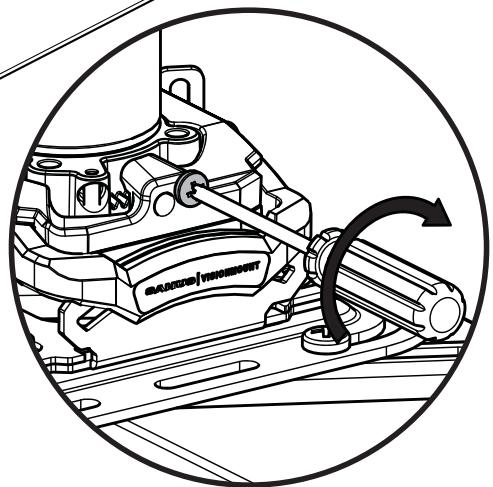
ADJUSTMENTS
PITCH Adjustment
Loosen PITCH adjustment locking screw using a #2 Phillips screwdriver. Turn PITCH micro-adjustment screw right or left using a #2 Phillips screwdriver until image is properly aligned on target. Tighten PITCH adjustment locking screw using a #2 Phillips screwdriver.
ATTENTION:
INFORMATIONS IMPORTANTES CONCERNANT LA SECURITE - CONSERVEZ CES INSTRUCTIONS - VEUILLEZ LIRE ATTENTIVEMENT LE MANUEL AVANT D'UTILISER CE PRODUIT
Specifications
Capacité de charge : 15,9 kg (35 lbs)
Ajustement autour de I'AXE VERTICAL ± 10^
Ajustement de l'INCLINAISON LATERALE ± 4^
Ajustement de l'INCLINAISON LONGITUDINALE ± 15^
Milestone AV Technologies and its affiliated corporations and subsidiaries (collectively, "Milestone"), intend to make this manual accurate and complete. However, Milestone makes no claim that the information contained herein covers all details, conditions, or variations. Nor does it provide for every possible contingency in connection with the installation or use of this product. The information contained in this document is subject to change without notice or obligation of any kind. Milestone makes no representation of warranty, expressed or implied, regarding the information contained herein. Milestone assumes no responsibility for accuracy, completeness or sufficiency of the information contained in this document.