SCENE MASTER - Audio mixer SYNQ AUDIO RESEARCH - Free user manual and instructions
Find the device manual for free SCENE MASTER SYNQ AUDIO RESEARCH in PDF.
| Product type | Audio mixing console / DMX controller |
| Brand and model | SYNQ AUDIO RESEARCH SCENE MASTER |
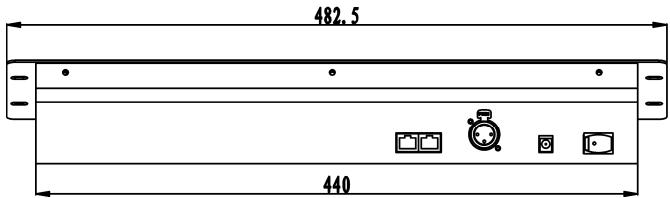
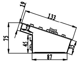
| Dimensions | 482 × 175 × 75 mm |
| Weight | 3.5 kg |
| Power supply | DC 9 V, 300 mA minimum via included mains adapter |
| Number of DMX channels | 16 channels, expandable up to 64 by linking 4 units |
| Channel types | DMX 512 (value 0-255) and MIDI (value 0-127) |
| Operating modes | Manual (dimmer) and Scene (scene programming and mixing) |
| Display | 4-character LED displaying DMX (0-512) and MIDI (0-127) values |
| Main functions | DMX control, MIDI control via USB, programming of 16 to 64 scenes, blackout, configuration memory |
| Inputs/Outputs | DMX output XLR 3-pin, USB-B (MIDI), RJ45 link (master/slave), DC input |
| Operating temperature | Maximum 45 °C |
| Safety class | Class III |
| Usage | Indoor only |
| Cleaning | With a slightly damp soft cloth; avoid solvents |
| Spare parts and repairability | No user-serviceable parts; refer to qualified technician |
| Included accessories | SCENE MASTER unit, DC adapter, instruction manual |
| Compliance | National and European standards, without radio interference |
Frequently Asked Questions - SCENE MASTER SYNQ AUDIO RESEARCH
User questions about SCENE MASTER SYNQ AUDIO RESEARCH
0 question about this device. Answer the ones you know or ask your own.
Ask a new question about this device
Download the instructions for your Audio mixer in PDF format for free! Find your manual SCENE MASTER - SYNQ AUDIO RESEARCH and take your electronic device back in hand. On this page are published all the documents necessary for the use of your device. SCENE MASTER by SYNQ AUDIO RESEARCH.
USER MANUAL SCENE MASTER SYNQ AUDIO RESEARCH
Copyright © 2010 by BEGLEC NV
t Hofveld 2C ~ B1702 Groot-Bijgaarden ~ Belgium
Reproduction or publication of the content in any manner, without express permission of the publisher, is prohibited.
CE
Version: 1.0


EN - DISPOSAL OF THE DEVICE
Dispose of the unit and used batteries in an environment friendly manner according to your country regulations.
FR-DECLASSES L'APPAREIL
Thank you for buying this JB Systems® product. To take full advantage of all possibilities, please read these operating instructions very carefully.
FEATURES
This unit is radio-interference suppressed. This product meets the requirements of the current European and national guidelines. Conformity has been established and the relevant statements and documents have been deposited by the manufacturer.
-
Extremely user-friendly 16channel DMX controller for all kinds of applications: stage, DJ, architectural lighting, ...
-
Seamless linking of up to 4 units to obtain a virtual controller with maximum 64channels and/or scenes!
-
2 user modes:
-
Dimmer mode: you can control 16 dimmer channels gradually (extendable up to 64channels)
-
Scene mode: you can create 16 scenes, each containing 16channels (extendable to 64scenes, each containing 64channels)
-
MIDI functionality via USB (16ch):
-
MIDI OUT: all channel faders + flash buttons can also send out MIDI-commandso you can control different MIDI applications (ex. Arkaos, Resolume, DMX-Creator, Daslight, ...)
-
MIDI IN: all scenes (16 up to 64) can be controlled by any external MIDI controller (seamless integration with MIDI-software such as Cubase, etc.), perfect for musicians etc.
-
The channel faders can be used to mix several scenes together.
-
Push buttons on top of all dimmer channels:
-
Dimmer mode: used as flash buttons
-
Scene mode: scenes can easily be switched on/off
-
Blackout function
-
Last output is preserved while the unit is switched off and on again (no need to push any button or deactive blackout): perfect for use on exhibition booths, shops, ...
- 4-digit LED-display shows DMX-values (0-255 or 0-100%) and MIDI-values (0-127)
BEFORE USE
Check the contents:
Check that the carton contains the following items:
SCENEMASTER unit
DC-Adapter
- User manual
Some important instructions:
- Before you start using this unit, please check if there's no transportation damage. Should there be any, do not use the device and consult your dealer first.
- Important: This device left our factory in perfect condition and well packaged. It is absolutely necessary for the user to strictly follow the safety instructions and warnings in this user manual. Any damage caused by mishandling is not subject to warranty. The dealer will not accept responsibility for any resulting defects or problems caused by disregarding this user manual.
- Keep this booklet in a safe place for future consultation. If you sell the fixture, be sure to add this user manual.
- To protect the environment, please try to recycle the packing material as much as possible.
SAFETY INSTRUCTIONS:

CAUTION
RISK OF ELECTRIC SHOCK DO NOT OPEN

CAUTION: To reduce the risk of electric shock, do not remove the top cover. No user-serviceable parts inside. Refer servicing to qualified service personnel only.

The lightning flash with arrowhead symbol within the equilateral triangle is intended to alert the use or the presence of un-insulated "dangerous voltage" within the product's enclosure that may be of sufficient magnitude to constitute a risk of electric shock.

The exclamation point within the equilateral triangle is intended to alert the user to the presence of important operation and maintenance (servicing) instructions in the literature accompanying this appliance.

This symbol means: indoor use only
This symbol means: Read instructions
This symbol means: Safety Class III appliance

The device is suitable for mounting on standard flammable surfaces. Standard flammable surfaces include building materials such as wood and wood-based materials more than 2mm thick.
- To prevent fire or shock hazard, do not expose this appliance to rain or moisture.
- To avoid condensation to be formed inside, allow the unit to adapt to the surrounding temperatures when bringing it into a warm room after transport. Condense sometimes prevents the unit from working at full performance or may even cause damages.
- This unit is for indoor use only.
- Don't place metal objects or spill liquid inside the unit. No objects filled with liquids, such as vases, shall be placed on this appliance. Electric shock or malfunction may result. If a foreign object enters the unit, immediately disconnect the mains power.
- No naked flame sources, such as lighted candles, should be placed on the appliance.
- Don't cover any ventilation openings as this may result in overheating.
- Prevent use in dusty environments and clean the unit regularly.
- Keep the unit away from children.
- Inexperienced persons should not operate this device.
Maximum save ambient temperature is 40^ . Don't use this unit at higher ambient temperatures. - Always unplug the unit when it is not used for a longer time or before you start servicing.
- The electrical installation should be carried out by qualified personal only, according to the regulations for electrical and mechanical safety in your country.
- Check that the available voltage is not higher than the one stated on the rear panel of the unit.
- The socket inlet shall remain operable for disconnection from the mains.
- The power cord should always be in perfect condition: switch the unit immediately off when the power cord is squashed or damaged. It must be replaced by the manufacturer, its service agent or similarly qualified persons in order to avoid a hazard
- Never let the power-cord come into contact with other cables!
- In order to avoid a hazard, the unit shall only be used with the AC-adaptor delivered with it. If the AC-adaptor is damaged, a same model adaptor shall be used only.
- In order to prevent electric shock, do not open the cover. Apart from the mains fuse there are no user serviceable parts inside.
- Never repair a fuse or bypass the fuse holder. Always replace a damaged fuse with a fuse of the same type and electrical specifications!
- In the event of serious operating problems, stop using the appliance and contact your dealer immediately.
- Please use the original packing when the device is to be transported.
- Due to safety reasons it is prohibited to make unauthorized modifications to the unit.
MAINTENANCE
Clean by wiping with a polished cloth slightly dipped with water. Avoid getting water inside the unit. Do not use volatile liquids such as benzene or thinner which will damage the unit.
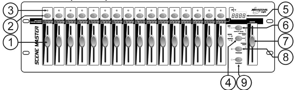
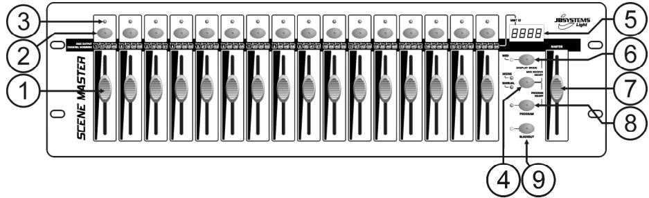
FUNCTIONS (FRONT)
-
CHANNEL FADERS: can be used for different purposes, depending on the working mode:
-
Manual mode: change the output level of the channel.
-
Scene mode: progressively recalls the scene that was programmed under this fader.
mark: in both working modes MIDI data (000-127) is sent through the USB-output (10) -
FLASH BUTTONS: can be used for different purposes, depending on the working mode:
-
Manual mode: used as channel FLASH button (max. output as long as the button is pressed)
- Scene mode: CHANNEL fader closed switch the programmed scene on/off.
- CHANNEL fader not closed used as scene FLASH button. (set scene at 100%)
Remark: in both working modes MIDI data (note on/off) is sent through the USB-output (10)
-
STATUS LED: information depends on the working mode:
-
Manual mode: lights up progressively, depending on the fader position.
-
Scene mode: dark while no scene is programmed (empty). lit while a scene is programmed but not active. blinking while a scene is programmed and active (shown on the output)
-
SCENE/MANUAL BUTTON: used to toggle between manual mode and scene mode:
-
Manual mode: each of the 16 CHANNEL faders can be used to manually set the output level.
- Scene mode: each of the 16 CHANNEL faders can contain a scene, scenes can be mixed manually.
While pressed together with the DISPLAY MODE button (6), you can set the controller in MIDI RECEIVE mode, see chapter "HOW TO USE" for more information.
- LED DISPLAY: shows different information, depending on the working mode and/or display mode. The first digit shows the unit number: unit1 is always the master. 2,3 or 4 is shown on the connected slaves.
-
DISPLAY MODE BUTTON: press the button to browse the different display modes:
-
Display mode 1: (led off) shows the DMX-values while a CHANNEL fader is moved (000 to 512).
- Display mode 2: (led off) shows the output in % while a CHANNEL fader is moved (0% to 100%)
- Display mode 3: (led on) shows the MIDI-values while a CHANNEL fader is moved (000 to 127).
-
MIDI channel: press the button until the led starts blinking, the display shows the selected MIDI channel. Press the button again until the led stops blinking. Also see chapter "HOW TO USE".
-
MASTER FADER: used to set the overall (master) DMX-output level. If several units are connected in master/slave, the master fader of unit1 (master unit) is used to control the output of all units together. Remark1: in both working modes MIDl data (000-127) is sent through the USB-output (10) Remark2: this fader is also used to set the desired MIDl channel, see chapter "HOW TO USE"
- PROGRAM BUTTON: used to program a scene under one of the CHANNEL faders. While pressed together with the SCENE/MANUAL button (4), you can set the controller in PROGRAM mode. For more information on using the PROGRAM button, see chapter "HOW TO USE".
- BLACKOUT BUTTON: used to shutoff the DMX-output. While used in MIDI RECEIVE mode, you can press this button for 2 seconds to reset all scenes (set all scenes to zero).
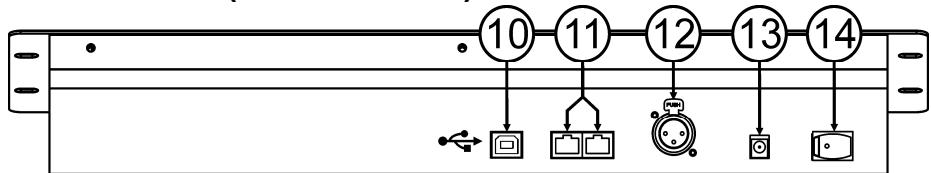
FUNCTIONS (REAR)
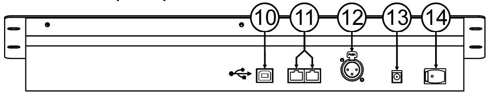
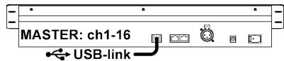
- USB-CONNECTION: used to connect the controller to a PC. In this way you can: control MIDIapplications, let other MIDI-applications control the Scenemaster or upgrade the firmware of the Scenemaster.
- LINK CONNECTORS: two RJ45 connectors used to link several Scenemasters together to obtain one virtual controller with more channels and scenes. You can use standard Cat-5 network patch cables.
- DMX-OUTPUT: used to connect and control all kinds of DMX-projectors and effects.
- DC-ADAPTER INPUT: connect the supplied DC-adapter here.
- POWER SWITCH: used to switch the controller on/off. The last working status is preserved, last active scenes will start automatically when you switch the Scenemaster back on.
CONNECTIONS
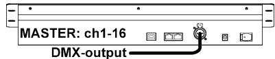
SIMPLE DMX-CONNECTION
Simply connect the DMX-output of the controller to all kinds of DMX-controllable equipment. The Scenemaster controls DMX-channels 1 to 16. To obtain more DMX-channels, just link several controllers together (see below).
SIMPLE MIDI-CONNECTION
Simply connect the USB-output of the controller to a PC. No drivers needed, these will be automatically installed.
Don't forget to set the controller to one of the 16 available MIDI-channels. See chapter "HOW TO USE" to learn more about using MIDI on the Scenemaster. To obtain more chann below).
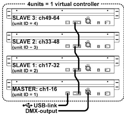
LINKING SEVERAL UNITS TOGETHER
If 16 channels and/or scenes is not enough for your application, don't worry: you can link several units together. The drawing shows the maximum of 4 units but you can also use the following combinations:
- 2 units: 1master + 1slave = 32 scenes + channels.
- 3 units: 1master + 2slaves = 48 scenes + channels.
- 4 units: 1master + 3slaves = 64 scenes + channels.
Linking the units is very easy: just use standard RJ-45 cat5 patch cables as used in Ethernet computer networks. (we also supply these cables: 0,5m = order code 5151 or 1,5m = order code 5152).
- Switch the controllers off.
- Connect the link output (11) of the master to the link input (11) of the 1^st slave.
- Connect the link output (11) of the 1^st slave to the link input (11) of the 2^nd slave. (if needed you can go up to 4 units.)
- Connect the DMX-cable to the DMX-output (12) of the master (!!).
- Switch the controllers on: the controllers will link automatically, on the left of each display you will see the "unit ID"-number. The master has always unit ID = 1 .
Important remark: the controls numbered 4 to 9 on the front panel drawing can ONLY be used on the master unit, on the slaves these controls are NOT used! (just imagine they are not on the slave units)
HOW TO USE - AS DMX-CONTROLLER
USE IN MANUAL MODE
The simplest way to use the Scenemaster:
- Press the SCENE/MANUAL button (4) to switch the controller to manual mode.
- Open the master fader (7).
- Use the CHANNEL faders (1) and FLASH buttons (2) to create the desired output.
Remark: use the DISPLAY button (6) to show the desired DMX-values on the display (0-512 or 0-100%).
USE IN SCENE MODE
A scene is a combination of different fader positions, this scene can be programmed under one fader.
Moving this fader up while the controller is set to scene mode will recall all these different fader positions in one time.
- Press the SCENE/MANUAL button (4) to switch the controller to scene mode.
- Open the master fader (7).
-
Two ways to recall scenes:
-
Use the CHANNEL faders (1) to recall the saved scenes gradually (0-100%). Once a CHANNEL fader is moved up a little, you can use the corresponding FLASH button (2) to set the scene instantly at 100%. When you release the FLASH button, the scene goes back to the output you have set with the CHANNEL fader. Several scenes can be mixed together.
- Use the FLASH buttons (2) to switch the saved scenes on/off. (fader of the corresponding scene should be closed!) Several scenes can be mixed together.
Remark: use the DISPLAY button (6) to show the desired DMX-values on the display (0-512 or 0-100%).
PROGRAM SCENES - BASED ON CHANNEL FADER POSITIONS
A. Scenes can only be programmed while the unit is set in "program mode". So first enter "program mode" by pressing the SCENE/MANUAL (4) and PROGRAM (8) buttons together red "program LED" is lit.
B. Use the SCENE/MANUAL button (4) to set the controller to "MANUAL".
C. Use the CHANNEL faders (1) to set the desired scene. (scene is present on the DMX-output)
D. Press the PROGRAM button (8) to check which channel faders already have scenes programmed:
- Channel with NO scene programmed: the STATUS LED (3) of this channel is dark.
- Channel with scene programmed: the STATUS LED (3) of this channel is lit.
→ You can save a new scene to an empty channel or overwrite an existing scene.
E. To program the current scene to a channel fader: keep the PROGRAM button (8) pressed while you press the FLASH button (2) of that channel. (the leds flash 3x to confirm that the scene was saved)
F. If you want to program other scenes, just repeat steps C to E.
G. Press the SCENE/MANUAL (4) and PROGRAM (8) buttons again to stop "program mode" (the red "program LED" turns dark)
PROGRAM SCENES - BASED ON EXISTING SCENES AND CHANNEL FADER POSITIONS
To speed up your work, you can also make new scenes by combining already existing scenes with simple fader positions. To do so you can switch between SCENE and MANUAL mode whenever you like.
A. Scenes can only be programmed while the unit is set in "program mode". So first enter "program mode" by pressing the SCENE/MANUAL (4) and PROGRAM (8) buttons together red "program LED" is lit.
B. Use the SCENE/MANUAL button (4) to set the controller to "SCENE".
C. Use the CHANNEL faders (1) to recall some the scenes. (scene is present on the DMX-output)
D. Use the SCENE/MANUAL button (4) to set the controller to "MANUAL".
E. Use the CHANNEL faders (1) to make adjustments on the current scene combination.
F. Press the PROGRAM button (8) to check which channel faders already have scenes programmed:
- Channel with NO scene programmed: the STATUS LED (3) of this channel is dark.
- Channel with scene programmed: the STATUS LED (3) of this channel is lit.
→ You can save a new scene to an empty channel or overwrite an existing scene.
G. To program the current scene to a channel fader: keep the PROGRAM button (8) pressed while you press the FLASH button (2) of that channel. (the leds flash 3x to confirm that the scene was saved)
H. If you want to program other scenes, just repeat steps B to G.
1. Press the SCENE/MANUAL (4) and PROGRAM (8) buttons again to stop "program mode" (the red "program LED" turns dark)
Remark: you can move a channel fader up and down to unlock it and set a new value. If you close the channel fader, the original value remains unchanged.
EDIT SCENES
Any programmed scene can still be edited using the following steps:
A. Scenes can only be edited while the unit is set in "program mode". So first enter "program mode" by pressing the SCENE/MANUAL (4) and PROGRAM (8) buttons together red "program LED" is lit.
B. Use the SCENE/MANUAL button (4) to set the controller to "SCENE".
C. Press the FLASH button (2) of the scene that needs to be edited: the corresponding status led (3) starts flashing while the scene is shown on the DMX-output, ready to be adapted.
D. Use the SCENE/MANUAL button (4) to set the controller to "MANUAL".
E. Use the CHANNEL faders (1) to make adjustments on the current scene combination.
F. Use the SCENE/MANUAL button (4) to set the controller again to "SCENE".
G. To save the changes, keep the PROGRAM button (8) pressed while you press the FLASH button (2) of the scene with flashing status led (3). (the leds flash 3x to confirm that the scene was saved)
H. If you want to edit other scenes, just repeat steps B to G.
1. Press the SCENE/MANUAL (4) and PROGRAM (8) buttons again to stop "program mode" (the red "program LED" turns dark)
Remark: you can move a channel fader up and down to unlock it and set a new value. If you close the channel fader, the original value remains unchanged.
DELETE SCENES
Any programmed scene overwritten by a new scene or deleted. Deleting a scene is in fact nothing more than overwriting it with an empty scene:
A. Scenes can only be deleted while the unit is set in "program mode". So first enter "program mode" by pressing the SCENE/MANUAL (4) and PROGRAM (8) buttons together red "program LED" is lit.
B. Use the SCENE/MANUAL button (4) to set the controller to "MANUAL"
C. Use the CHANNEL faders (1) to make an "empty scene": all faders are closed + status leds are dark.
D. Keep the PROGRAM button (8) pressed (status leds of channels with scenes are lit): and push the FLASH buttons (2) of the scenes that you want to remove. The status leds (3) of the deleted scenes will turn dark.
E. Press the SCENE/MANUAL (4) and PROGRAM (8) buttons again to stop "program mode" (the red "program LED" turns dark)
HOW TO USE - MIDI FUNCTIONS
MIDI CHANNEL SETUP
To ensure that the controller sends/receives MIDI-data on the desired channel, follow these steps:
- Press the DISPLAY MODE button (6) for about 3seconds, until the led starts flashing.
- Use the MASTER fader (7) to select the desired MIDI-channel. (01 to 16)
- Press the DISPLAY MODE button (6) for about 3seconds, until the led stops flashing.
Done!
MIDI OUT FUNCTION (USE AS MIDI CONTROLLER)
Used to control all kinds of MIDI-applications. For example you can use the Scenemaster to control:
- Video software like: Arkaos GrandVJ, Resolume, and many other ...
- DMX light software like: DMX-Creator, Daslight, Sweetlight, and many other ...
- All kinds of other MIDI controllable applications
In both scene mode and manual mode MIDI is sent. (DMX and MIDI can be used together)
Just use the CHANNEL faders (1), MASTER fader (7) and FLASH buttons (2) to control your MIDI applications running on PC. (MASTER fader only works on unit 1)
Remark: use the DISPLAY button (6) to switch the display to MIDl-values (0-127).
MIDI COMMANDS
Control Change messages are sent with status 0xBn kk vv, where n is the MIDI-channel, for the specified CC controller. Thus the controller MIDI ID is indicated with the channel along with the CC number.
| kk | Button and fader | vv (0-127) |
| 0-15 | Button and Fader 1-6 (UNIT 1) | Button(0/127) and Fader(0--127) 1-16 value( UNIT 1) |
| 16-31 | Button and Fader 1-16 (UNIT 2) | Button(0/127) and Fader(0--127) 1-16 value( UNIT 2) |
| 32-47 | Button and Fader 1-16( UNIT 3) | Button(0/127) and Fader(0--127) 1-16 value( UNIT 3) |
| 48-63 | Button and Fader 1-16( UNIT 4) | Button(0/127) and Fader(0--127) 1-16 value( UNIT 4) |
| ...... | ...... | ...... |
| 125 | Master fader( UNIT 1) | Master fader value( Only UNIT 1) |
| 126 | Blackout button | 0/127 (Only UNIT 1) |
| ...... | ...... | ...... |
MIDI IN FUNCTION (CONTROLLED BY EXTERNAL MIDI CONTROLLER)
Up to 64 scenes can be controlled by MIDI-controllers and sequencers, perfect for musicians.
The Scenemaster should be set in "MIDI RECEIVE" mode: press the SCENE/MANUAL-button (4) and DISPLAY MODE-button (6) together.
In "MIDI RECEIVE" mode:
- The display shows "Mld" to indicate that the receive mode is active.
- The Scenemaster does NOT send any MIDI-command, it only listens to incomings MIDI-data.
- Except for the BLACKOUT button (9) pressing buttons and moving faders has no effect.
Only the BLACKOUT-button (9) is still active:
- Press the BLACKOUT-button shortly: DMX-output goes in blackout but scenes are still active.
- Press the BLACKOUT-button for 2 seconds: all scenes are switched off. (in case something goes wrong in the MIDI-communication)
MIDI COMMANDS
Switching scenes on/off: 0x9n kk 127
Fading scenes gradually: 0xBn kk vv (vv: 0-127)
Blackout function: 0x9n kk 127
Remark: "n" = MIDI channel.
| kk | Function | Function explain |
| 0-15 | SCENE1-16 | Turn on/off and fade in/out Scenes 1-16(UNIT 1) |
| 16-31 | SCENE17-32 | Turn on/off and fade in/out Scenes 17-32 (UNIT 2) |
| 32-47 | SCENE33-48 | Turn on/off and fade in/out Scenes 33-48 (UNIT 3) |
| 48-63 | SCENE49-64 | Turn on/off and fade in/out Scenes 49-64 (UNIT 4) |
| ...... | ...... | ...... |
| 125 | MASTER | Master fader in/out (ALL UNITS) |
| 126 | BLACKOUT | Turn on/off Blackout (ALL UNITS) |
| ...... | ...... | ...... |
HOW TO USE - AS MIDI-CONTROLLER
If needed, updating the firmware in the Scenemaster is easy, just follow these steps:
- Surf to the Scenemaster product page on our website (www.jbsystems.be) to check if new firmware is available in the download section.
- Download the file and unzip it: now you have a file named "SCM-1.SUP"
- Put this file in a directory on your PC.
- Connect the Scenemaster to one of the USB-inputs of your PC.
- Turn the power of the Scenemaster OFF.
-
Press the "FLASH-button of channel 16" and the "PROGRAM-button" (8) together while you switch the Scenemaster back on, you will notice 2 things:
-
The display on the Scenemaster shows "USb"
-
A new window, with directory named "SCENEMASTER" opens on your PC-screen.
-
This "SCENEMASTER" directory contains a file named "SCM-1.SUP":
-
First delete the current file from the "SCENEMASTER" directory.
-
Now copy the new "SCM-1.SUP" file (downloaded from our website) in the directory.
-
Use the power switch (14) to switch the Scenemaster off.
- After 5 seconds turn the unit back on: at startup the display will show the new software version.
Important remark: do NOT switch the Scenemaster off while no new file was copied to the "SCENEMASTER" directory, this will make the Scenemaster inoperable.
SPECIFICATIONS
Power Input: DC 9V 300mA minimum.
AC/DC Power adapter: AC 230V, 50Hz → 9Vdc / 300mA (or more)
Preserved working status: last working status, 5s before shutdown, is preserved.
DMX outputs: 3pin XLR
MIDI in/out: USB-B (slave) connector
Size: 482 × 175 × 75 ~mm (see drawing)
Weight: 3,5 kg
Every information is subject to change without prior notice
You can download the latest version of this user manual on our website: www.beglec.com
MODE D'EMPLOI
FONCTIONS (FACE AVANT)
FONCTIONS (FACE ARRIÈRE)
Pourmettrelesscenesenouhorservice:
0x9n kk 127