
HHVP64FALK - Kitchen hood HOTPOINT - Free user manual and instructions
Find the device manual for free HHVP64FALK HOTPOINT in PDF.
| Product type | Kitchen hood |
| Brand | HOTPOINT |
| Model | HHVP64FALK |
| Height | 69 - 104 cm (adjustable) |
| Width | 59.5 cm |
| Depth | 15 cm |
| Air outlet diameter | 15 cm (reducible to 12.5 or 12 cm) |
| Power supply | See rating plate (generally 220-240 V) |
| Total absorbed power | See rating plate |
| Lighting | LED, replacement by authorized service |
| Number of suction speeds | 3 speeds + timed boost (5 min) |
| Type of controls | Electronic buttons with display and timer |
| Grease filter | Metallic, dishwasher safe (once a month) |
| Charcoal filter | Replace every 4 months max, not washable |
| Extraction mode | Extracting or recirculating (accessory kit required for recirculating) |
| Safety sensor | Yes (activates in case of high temperature) |
| Minimum distance above hob | 55 cm (electric hob) or 70 cm (gas/mixed) |
| Maintenance | Monthly cleaning with damp cloth and neutral detergent |
| Environmental protection | Recycling according to WEEE directive 2012/19/EC |
Frequently Asked Questions - HHVP64FALK HOTPOINT
User questions about HHVP64FALK HOTPOINT
0 question about this device. Answer the ones you know or ask your own.
Ask a new question about this device
Download the instructions for your Kitchen hood in PDF format for free! Find your manual HHVP64FALK - HOTPOINT and take your electronic device back in hand. On this page are published all the documents necessary for the use of your device. HHVP64FALK by HOTPOINT.
USER MANUAL HHVP64FALK HOTPOINT
flowchart
graph TD
    A["Room 1"] --> B["Window"]
    B --> C["Door"]
    C --> D["Window"]
    D --> E["Window"]
    E --> F["Window"]
    F --> G["Window"]
    G --> H["Window"]
    H --> I["Window"]
    I --> J["Window"]
    J --> K["Window"]
    K --> L["Window"]
    L --> M["Window"]
    M --> N["Window"]
    N --> O["Window"]
    O --> P["Window"]
    P --> Q["Window"]
    Q --> R["Window"]
    R --> S["Window"]
    S --> T["Window"]
    T --> U["Window"]
    U --> V["Window"]
    V --> W["Window"]
    W --> X["Window"]
    X --> Y["Window"]
    Y --> Z["Window"]
    Z --> AA["Window"]
    AA --> AB["Window"]
    AB --> AC["Window"]
    AC --> AD["Window"]
    AD --> AE["Window"]
    AE --> AF["Window"]
    AF --> AG["Window"]
    AG --> AH["Window"]
    AH --> AI["Window"]
    AI --> AJ["Window"]
    AJ --> AK["Window"]
    AK --> AL["Window"]
    AL --> AM["Window"]
    AM --> AN["Window"]
    AN --> AO["Window"]
    AO --> AP["Window"]
    AP --> AQ["Window"]
    AQ --> AR["Window"]
    AR --> AS["Window"]
    AS --> AT["Window"]
    AT --> AU["Window"]
    AU --> AV["Window"]
    AV --> AW["Window"]
    AW --> AX["Window"]
    AX --> AY["Window"]
RU
natural_image
Line drawing of a mechanical device with a screwdriver and housing, no text or symbols present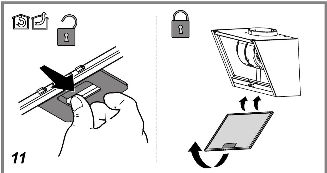
RU
⚠️ ОБЩИЕ ПРАВИЛА ТЕХНИКИ БЕЗОПАСНОСТИ
natural_image
Illustration of a hand using a tool to adjust or install a mechanical component (no text or symbols visible)natural_image
Technical line drawing of a mechanical device with three views (front, side, and top) showing internal components like gears and housing (no text or symbols)Замена ламп
natural_image
Illustration of a hand using a hot pot to test a component, with close-up details showing internal wiring (no text or symbols)УТИЛИЗАЦИЯ
natural_image
Illustration of a hand holding a mechanical clamp or bracket with a tool, no text or symbols presentnatural_image
Technical line drawing of a mechanical assembly with three views (top, front, side), showing internal components like gears and housing (no text or labels)Лампаларды ауыстыру
natural_image
Illustration of a hand holding a small electronic component with wires, alongside a close-up of its connector (no text or symbols present)ЖОЮ
natural_image
Illustration of a hand holding a mechanical clamp or bracket with a tool, no text or symbols presentnatural_image
Technical line drawing of a mechanical device with three views (top, front, side), showing internal components and no text or symbols.natural_image
Diagram showing a hand pressing a component into a pot, with an inset close-up of the plug assembly (no text or symbols present)ÉLIMINATION
natural_image
Illustration of a hand using a tool to adjust or install a mechanical component (no text or symbols visible)natural_image
Technical line drawing of a mechanical device with three views (front, side, and top) showing internal components like gears and fans (no text or symbols)Izzók cseréje
natural_image
Diagram showing a hand pressing a component into a pot, with an inset close-up of its plug assembly (no text or symbols present)HULLADÉK KEZELÉS
natural_image
Illustration of a hand using a tool to adjust or install a mechanical component (no text or symbols visible)natural_image
Technical line drawing of a mechanical device with three views (front, side, and top) showing internal components like gears and housing (no text or symbols)Wymiana żarówek
natural_image
Diagram showing a hand holding a small cylindrical component with a base, connected to a connector pin (no text or symbols present)ZŁOMOWANIE
natural_image
Illustration of a hand holding a mechanical clamp or bracket with a tool, no text or symbols presentnatural_image
Technical line drawing of a mechanical device with three views (front, side, and top) showing internal components like gears and fans (no text or symbols)Zamjena žarulja
natural_image
Illustration of a hand holding a small electronic component with a close-up view showing its internal structure and wiring (no text or symbols present)ODLAGANJE OTPADA
Ovaj aparat je označen u skladu s Europskim pravilima 2012/19/EC, Waste Electrical and Electronic Equipment (WEEE). Provjerite jeste li odveli na otpad ovaj proizvod u skladu s lokalnim pravilima, korisnik doprinosi sprečavanju i uklanjanju eventualnih negativnih posljedica za okolinu i za zdravlje.

Ovaj simbol na proizvodu ili na dokumentaciji koja ga prati ukazuje da se ovaj proizvod ne smije tretirati kao ostali kuhinjski otpad nego treba biti odveden u odgovarajući sabirni centar gdje se zbrinjavaju električni i elektronski uređaji. Zbrinite takve uređaje tako da se pridržavate lokalnih pravila za uklanjanje otpadaka. Za dobivanje daljnjih informacija o zbrinjavanju ovakvih aparata, obratite se lokalnim uredima, sabirnim mjestima za sakupljanje otpada ili trgovini u kojoj ste kupili ovaj proizvod.
Aparati dizajnirani, testirani i proizvedeni u skladu sa:
- Sigurnosnim propisima: EN/IEC 60335-1; EN/IEC 60335-2-31, EN/IEC 62233.
- Propisima o performansama: EN/IEC 61591; ISO 5167-1; ISO 5167-3; ISO 5168; EN/IEC 60704-1; EN/IEC 60704-2-13; EN/IEC 60704-3; ISO 3741; EN 50564; IEC 62301.
- EMC: EN 55014-1; CISPR 14-1; EN 55014-2; CISPR 14-2; EN/IEC 61000-3-2; EN/IEC 61000-3-3. Savjeti za ispravnu uporabu u cilju smanjenja utjecaja na okoliš: Uključite kuhinjsku napu na minimalnu brzinu kada počnete s kuhanjem i držite je uključenom još nekoliko minuta nakon završenog kuhanja. Povećajte brzinu samo u slučaju velike količine dima i pare i koristite pojačanu brzinu (e) samo u ekstremnim situacijama. Zamijenite filtere od ugljena samo kada je to potrebno kako biste održali učinkovitu redukciju neugodnih mirisa. Očistite filtere za odstranjivanje masnoće kada je to potrebno za održavanje dobre učinkovitosti tih istih filtera. Koristite maksimalni promjer sustava dimovoda navedenog u ovom priručniku da biste optimizirati učinkovitost i smanjili buku.
GREŠKE U RADU
⚠ SIGURANTĂ GENERALĂ
natural_image
Illustration of a hand holding a mechanical clamp or bracket with a tool, no text or symbols presentnatural_image
Technical line drawing of a mechanical device with multiple components and housing (no text or symbols)natural_image
Diagram showing a hand holding a small cylindrical component with a base, connected to a connector pin (no text or symbols present)ELIMINARE
natural_image
Illustration of a hand holding a mechanical clamp or bracket with a tool, no text or symbols presentnatural_image
Technical line drawing of a mechanical device with three views (front, side, and top) showing internal components like gears and fans (no text or symbols)Výměna svítidel
natural_image
Diagram showing a hand pressing a component into a pot, with an inset close-up of the plug assembly (no text or symbols present)LIKVIDACE ODPADU
natural_image
Illustration of a hand using a tool to adjust or install a mechanical component (no text or symbols visible)natural_image
Technical line drawing of a mechanical device with three views (front, side, and top) showing internal components like gears and housing (no text or symbols)Výmena žiaroviek
natural_image
Diagram showing a hand holding a small cylindrical component with a base, connected to a connector pin (no text or symbols present)LIKVIDÁCIA
natural_image
Illustration of a hand using a tool to adjust or install a mechanical component (no text or symbols visible)natural_image
Technical line drawing of a mechanical device with three views (front, side, and top) showing internal components like gears and fans (no text or symbols)Подмяна на лампите
natural_image
Diagram showing a hand pressing a component into a pot, with an inset close-up of its plug assembly (no text or symbols present)РЕЦИКЛИРАНЕ
- Waste Electrical and Electronic Equipment (WEEE).
natural_image
Illustration of a hand using a tool to adjust or install a mechanical component (no text or symbols visible)natural_image
Technical line drawing of a mechanical device with three views (front, side, and top) showing internal components like gears and fans (no text or symbols)Заміна лампочок
natural_image
Illustration of a hand holding a small electronic component with a close-up view showing its internal structure (no text or symbols present)УТИЛІЗАЦІЯ
natural_image
Illustration of a hand using a tool to adjust or install a mechanical component (no text or symbols visible)natural_image
Technical line drawing of a mechanical device with three views (front, side, and top) showing internal components like gears and housing (no text or symbols)natural_image
Diagram showing a hand pressing a component into a pot, with an inset close-up of the plug being inserted (no text or symbols present)АПОРРІΨН
natural_image
Illustration of a hand using a tool to adjust or install a mechanical component (no text or symbols visible)Održavanje karbonskog filtera
natural_image
Technical line drawing of a mechanical device with three views (front, side, and top) showing internal components like gears and fans (no text or symbols)Zamena lampa
Isključite aparat sa električne mreže.
Upozorenje! Pre nego što dotaknete lampe budite sigurni da su se ohladile.
Kuhinjska napa je opremljena sistemom rasvete koja se bazira na LED tehnologiji.
natural_image
Illustration of a hand holding a small electronic component with wires, alongside a close-up of its internal wiring (no text or symbols present)ODLAGANJE
Ovaj aparat je označen u skladu sa Evropskom Direktivom 2012/19/EC, Waste Electrical and Electronic Equipment (WEEE). Proverite da li je ovaj proizvod odložen na pravilan način jer na taj način korisnik pomaže u sprečavanju eventualnih negativnih posledica za zdravlje i za okolinu.

Simbol na proizvodu ili na propratnoj dokumentaciji ilustruje da se ovaj proizvod ne sme tretirati kako kućni otpad nego treba da se odloži na prikladnom sabirnom mestu za odbacivanje električnih i elektronskih aparata. Odložite ovaj otpad na način da se strogo pridržavate lokalnih pravilnika o odlaganju smeća. Za dobijanje detaljnijih informacija o tretmanu, odlaganju i ponovnom korišćenju ovog proizvoda, stupite u kontakt sa prikladnim lokalnim ustanovama, službom za sakupljanje kućnog otpada i/ili sa prodavnicom u kojoj ste kupili ovaj proizvod.
natural_image
Illustration of a hand holding a mechanical clamp or bracket with a tool, no text or symbols presentnatural_image
Technical line drawing of a mechanical device with three views (front, side, and top) showing internal components like gears and housing (no text or symbols)Zamenjava žarnic
Izključite električno napajanje naprave.
Pozor! Preden se žarnic dotaknete, se prepričajte, ali so hladne.
Napa ima sistem osvetlitve, ki temelji na LED tehnologiji.
natural_image
Illustration of a hand holding a small electronic component with a close-up view showing its internal structure and wiring (no text or symbols present)ODLAGANJE
natural_image
Illustration of a hand holding a mechanical clamp or bracket with a tool, no text or symbols presentnatural_image
Technical line drawing of a mechanical device with multiple components and housing (no text or symbols)natural_image
Diagram showing a hand pressing a component into a pot, with an inset close-up of the plug being inserted (no text or symbols present)SMALTIMENTO
- Before any cleaning or maintenance operation, disconnect hood from the mains by removing the plug or disconnecting the mains electrical supply.
• Always wear work gloves for all installation and maintenance operations. - This appliance can be used by children aged from 8 years and above and persons with reduced physical, sensory or mental capabilities or lack of experience and knowledge if they have been given supervision or instruction concerning use of the appliance in a safe way and understand the hazards involved.
- Children shall not be allowed to tamper with the controls or play with the appliance.
- Cleaning and user maintenance shall not be made by children without supervision.
- The premises where the appliance is installed must be sufficiently ventilated, when the kitchen hood is used together with other gas combustion devices or other fuels.
- The hood must be regularly cleaned on both the inside and outside (AT LEAST ONCE A MONTH).
- This must be completed in accordance with the maintenance instructions provided. Failure to follow the instructions provided regarding the cleaning of the hood and filters will lead to the risk of fires.
- Do not flambé under the range hood.
- Do not remove filters during cooking.
- For lamp replacement use only lamp type indicated in the Maintenance/Replacing lamps section of this manual.
The use of exposed flames is detrimental to the filters and may cause a fire risk, and must therefore be avoided in all circumstances.
Any frying must be done with care in order to make sure that the oil does not overheat and ignite.
CAUTION: Accessible parts of the hood may become hot when used with cooking appliances.
- Do not connect the appliance to the mains until the installation is fully complete.
- With regards to the technical and safety measures to be adopted for fume discharging it is important to closely follow the regulations provided by the local authorities.
- The air must not be discharged into a flue that is used for exhausting fumes from appliance burning gas or other fuels.
- Do not use or leave the hood without the lamp correctly mounted due to the possible risk of electric shocks.
- Never use the hood without effectively mounted grids.
- The hood must NEVER be used as a support surface unless specifically indicated.
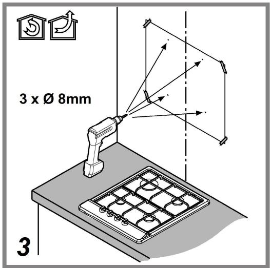
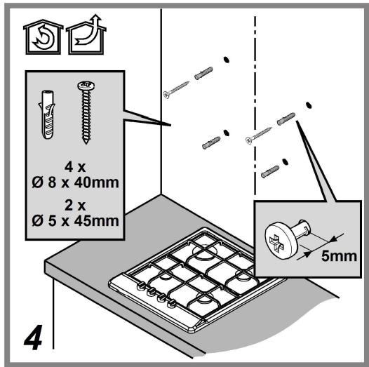
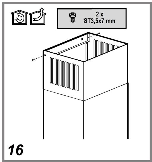
- Use only the fixing screws supplied with the product for installation or, if not supplied, purchase the correct screws type.
- Use the correct length for the screws which are identified in the Installation Guide.
- In case of doubt, consult an authorized service assistance center or similar qualified person.
▲ WARNING!
- Failure to install the screws or fixing device in accordance with these instructions may result in electrical hazards.
- Do not use with a programmer, timer, separate remote control system or any other device that switches on automatically.
The hood can look different to that illustrated in the drawings in this booklet. The instructions for use, maintenance and installation, however, remain the same.
Closely follow the instructions set out in this manual. All responsibility, for any eventual inconveniences, damages or fires caused by not complying with the instructions in this manual, is declined. This appliance is intended to be used in household and similar application such as: - staff kitchen areas in shop, offices and other working environments; - farm houses; - by clients in hotels, motels and other residential type environments; - bed and breakfast type environments.
- It is important to conserve this booklet for consultation at any moment. In the case of sale, cession or move, make sure it is together with the product.
- Read the instructions carefully: there is important information about installation, use and safety.
- Do not carry out electrical or mechanical variations on the product or on the discharge conduits.
- Before proceeding with the installation of the appliance verify that there are no damaged all components. Otherwise contact your dealer and do not proceed with the installation.
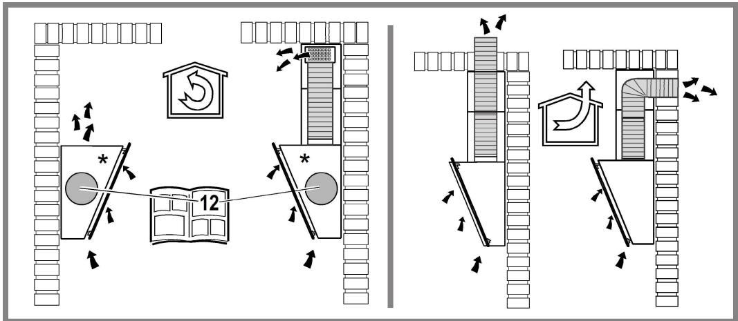
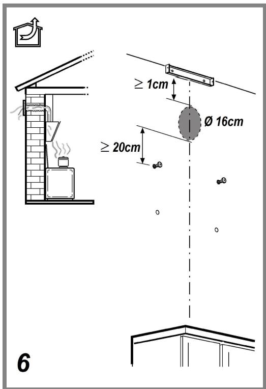
The minimum distance between the supporting surface for the cooking equipment on the hob and the lowest part of the range hood must be not less than 55cm from electric cookers and 70cm from gas or mixed cookers.
If the instructions for installation for the gas hob specify a greater distance, this must be adhered to.
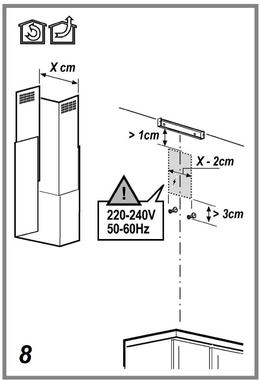
ELECTRICAL CONNECTION
The mains power supply must correspond to the rating indicated on the plate situated inside the hood. If provided with a plug connect the hood to a socket in compliance with current regulations and positioned in an accessible area, after installation. If it not fitted with a plug (direct mains connection) or if the plug is not located in an accessible area, after installation, apply a double pole switch in accordance with standards which assures the complete disconnection of the mains under conditions relating to over-current category III, in accordance with installation instructions.
▲ WARNING!
Before re-connecting the hood circuit to the mains supply and checking the efficient function, always check that the mains cable is correctly assembled.
Replacing the power cable
The hood is provided with a special power cable; if the cable is damaged, request a new one from Technical Service.
AIR VENT
(for the suction versions)
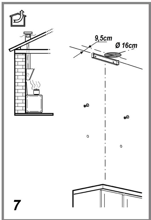
Connect the hood and discharge holes on the walls with a diameter equivalent to the air outlet (connection flange).
Using the tubes and discharge holes on walls with smaller dimensions will cause a diminution of the suction performance and a drastic increase in noise.
Any responsibility in the matter is therefore declined.
! Use a duct of the minimum indispensable length.
! Use a duct with as few elbows as possible (maximum elbow angle: 90°).
! Avoid drastic changes in the duct cross-section.
! The company declines any responsibility whenever these regulations are not respected.
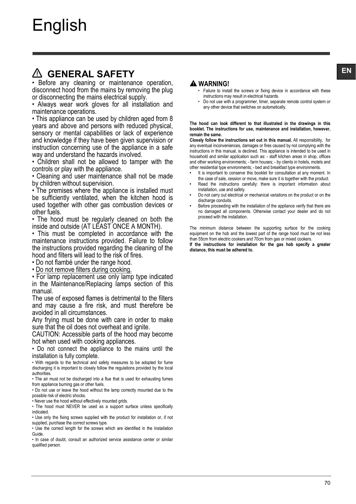
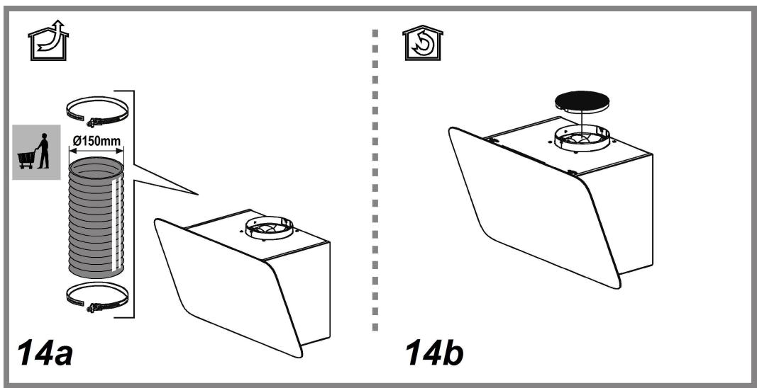
FILTERING OR DUCTING?
! Your cooker hood is ready to be used in suction version.
To use the hood in filtering version the special ACCESSORY KIT must be installed.
Check on the first pages of this manual if the ACCESSORY KIT is furnished or must be bought separately.
Note: If furnished, in certain cases, the additional activated carbon filtering system may be installed on the hood.
Information about the conversion of the hood from suction version to filtering version is present in this manual.

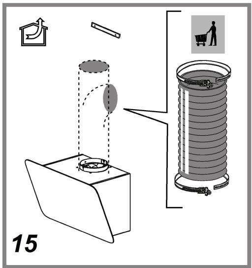
Ducting version
In this case the fumes are conveyed outside of the building by means of a special pipe connected with the connection ring located on top of the hood.
CAUTION!
The exhausting pipe is not supplied and must be purchased apart.
Diameter of the exhausting pipe must be equal to that of the connection ring.
CAUTION!
If the hood is supplied with active charcoal filter, then it must be removed.

Filter version
The aspirated air will be degreased and deodorised before being fed back into the room.
In order to use the hood in this version, you have to install a system of additional filtering based on activated charcoal.
CONTROLS
The hood is fitted with a control panel with aspiration speed selection control and a light switch to control cooking area lights.
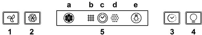
- OFF / Extraction speed (power) decrease button
- ON / Extraction speed (power) increase button
Note: The intensive extraction speed (power) is timed and lasts for 5 minutes (indicator c flashes); the hood then reverts to extraction speed (power) 2.
- ON/OFF Timer button: delays the deactivation of the selected extraction speed (power) by 5 minutes.
Note: the button is also used for the "Filter saturation signal reset" function
- Light ON/OFF button
- Display, shows:
a. Extraction speed (power): the indicator rotates according to the selected extraction speed (power).
Safety operation: the indicator flashes.
b. Grease filter saturation: comes on when filter maintenance is required.
c. Timer
d. Active carbon filter saturation: comes on when filter maintenance is required.
Note: this function is normally disabled and should only be activated if the hood is used as a filter version (with carbon filter fitted).
To do so, proceed as follows:
- switch off the hood
- press and hold buttons 1 and 3 at the same time, until the indicator stops flashing (indicator disabled) and is lit steadily (indicator enabled).
- release the buttons.
To deactivate it, repeat the procedure: the indicator will no longer be lit steadily (indicator enabled) and will flash instead (indicator disabled).
e. Lighting
Safety operation
The hood has a sensor which, in the event of a sudden increase in temperature, activates the appliance until the temperature drops significantly.
Filter saturation signal reset
After carrying out filter maintenance, press and hold button 3 until indicator.
MAINTENANCE
Cleaning
Clean using ONLY a cloth dampened with neutral liquid detergent. DO NOT CLEAN WITH TOOLS OR INSTRUMENTS. Do not use abrasive products. DO NOT USE ALCOHOL!
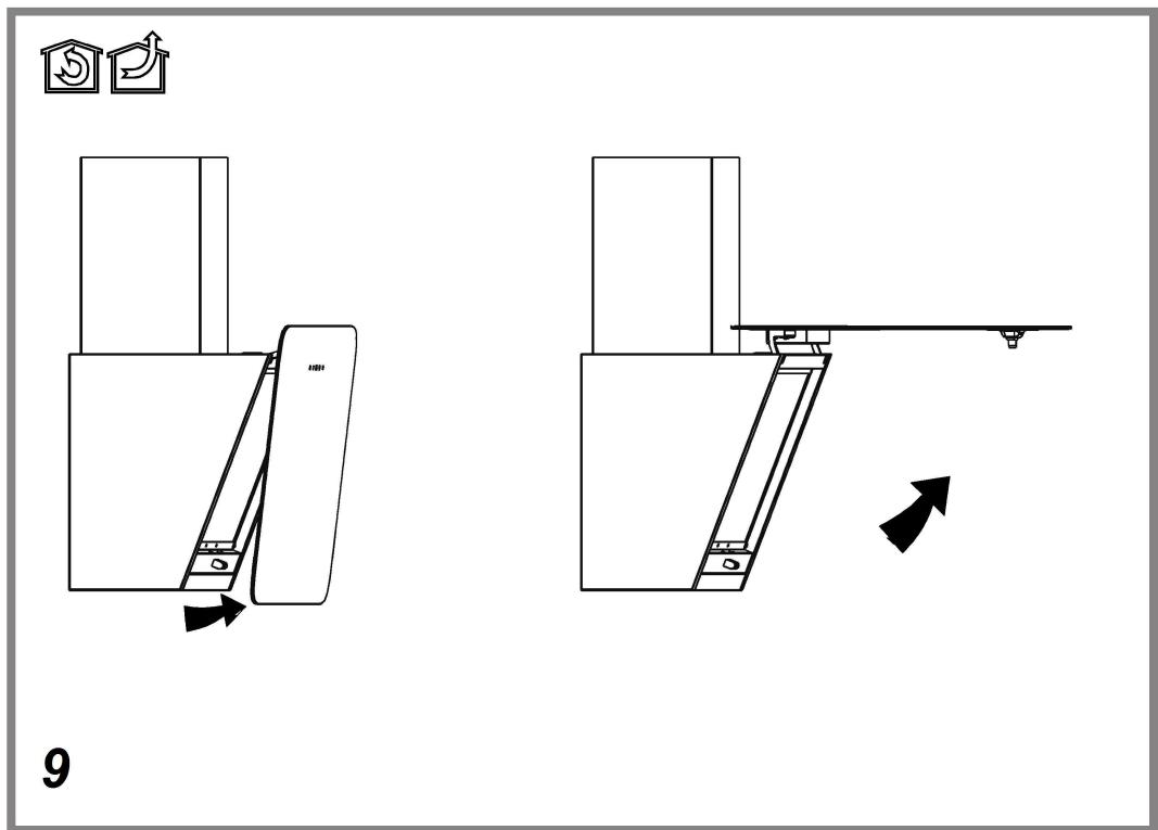
Perimeter aspiration panel
Clean the perimeter aspiration panel with the same frequency as the ant-fats filter, using a cloth and not too concentrated liquid detergent. Do not use abrasive substances.
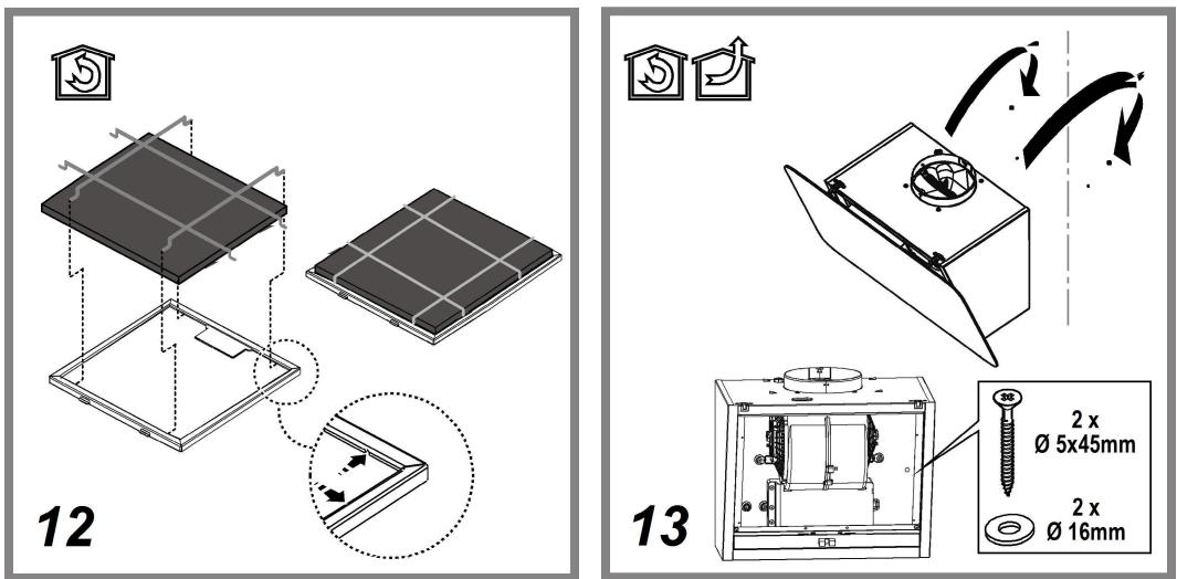
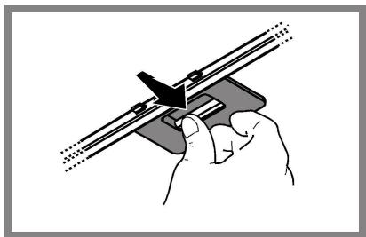
Maintenance of the anti-grease filters
Traps cooking grease particles.
This must be cleaned once a month (or when the filter saturation indication system – if envisaged on the model in possession – indicates this necessity) using non aggressive detergents, either by hand or in the dishwasher, which must be set to a low temperature and a short cycle.
When washed in a dishwasher, the grease filter may discolor slightly, but this does not affect its filtering capacity.
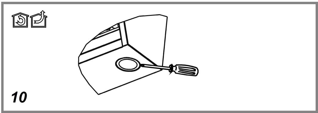
To remove the grease filter, pull the spring release handle.
natural_image
Illustration of a hand holding a mechanical clamp or bracket with a tool, no text or symbols presentMaintenance of the charcoal filter
It absorbs unpleasant odors caused by cooking.
The saturation of the charcoal filter occurs after more or less prolonged use, depending on the type of cooking and the regularity of cleaning of the grease filter.
In any case it is necessary to replace the cartridge at least every four mounths (or when the filter saturation indication system – if envisaged on the model in possession – indicates this necessity). The charcoal filter may NOT be washed or regenerated.
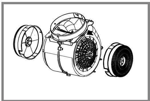
Circular charcoal filter
Apply one on each side as cover to both the shield grids of the motor impeller, then turn clockwise.
For the disassembly, turn counter-clockwise.
natural_image
Technical line drawing of a mechanical device with multiple housing components (no text or symbols)Replacing lamps
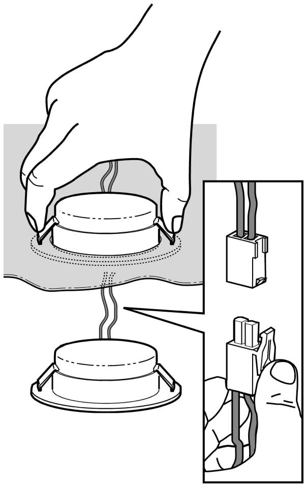
Disconnect the appliance from the electricity.
Warning! Prior to touching the light bulbs ensure they are cooled down.
The hood is equipped with a lighting system based on LED technology.
The LEDs guarantee an optimum lighting, a duration up to 10 times as long as the traditional lamps and allow to save 90% electrical energy.
To replace lights, contact authorised spare part center.
natural_image
Diagram showing a hand holding a small component being heated by a lamp, with an inset close-up of its cable being inserted (no text or symbols present)DISPOSAL
- This appliance is marked according to the European directive 2012/19/EC on Waste Electrical and Electronic Equipment (WEEE).
- By ensuring this product is disposed of correctly, you will help prevent potential negative consequences for the environment and human health, which could otherwise be caused by inappropriate waste handling of this product.

- The symbol ■ on the product, or on the documents accompanying the product, indicates that this appliance may not be treated as household waste. Instead it should be taken to the appropriate collection point for the recycling of electrical and electronic equipment. Disposal must be carried out in accordance with local environmental regulations for waste disposal.
- For further detailed information regarding the process, collection and recycling of this product, please contact the appropriate department of your local authorities or the local department for household waste or the shop where you purchased this product.
Appliance designed, tested and manufactured according to:
• Safety: EN/IEC 60335-1; EN/IEC 60335-2-31, EN/IEC 62233.
• Performance: EN/IEC 61591; ISO 5167-1; ISO 5167-3; ISO 5168; EN/IEC 60704-1; EN/IEC 60704-2-13; EN/IEC 60704-3; ISO 3741; EN 50564; IEC 62301.
- EMC: EN 55014-1; CISPR 14-1; EN 55014-2; CISPR 14-2; EN/IEC 61000-3-2; EN/IEC 61000-3-3. Suggestions for a correct use in order to reduce the environmental impact: Switch ON the hood at minimum speed when you start cooking and kept it running for few minutes after cooking is finished. Increase the speed only in case of large amount of smoke and vapor and use boost speed(s) only in extreme situations. Replace the charcoal filter(s) when necessary to maintain a good odor reduction efficiency. Clean the grease filter(s) when necessary to maintain a good grease filter efficiency. Use the maximum diameter of the ducting system indicated in this manual to optimize efficiency and minimize noise.
MALFUNCTIONS
If something appears not to be working properly, do the following simple checks before calling Technical Service:
• If the hood is not working:
Check that:
- The power has not been disconnected.
- A speed has been selected.
• If the hood performs inefficiently:
Check that:
- The motor speed selected is sufficient for the amount of smoke and
vapours released. - The kitchen is sufficiently ventilated to allow air intake.
- The charcoal filter is not worn (hood in filtering version).
• If the hood has turned off during normal functioning:
Check that:
- The power has not been disconnected.
- the omnipolar disconnection device has not tripped.
If the hood fails to operate correctly, briefly disconnect it from the mains power supply for almost 5 sec. Then connect it in again and try once more before contacting the Technical Assistance Service.
TECHNICAL DATA
| Model | Height (cm) | Width (cm) | depth (cm) | ∅ of exhaust tube(cm) |
| HHVP 6.4F AL K/1 | 69 -104 | 59,5 | 15 | 15-12,5-12 |
Please check the plate in order to verify the total absorption and the light absorption.


Components not provided with the product
⚠️ GENEL GÜVENLİK
natural_image
Illustration of a hand holding a mechanical clamp or bracket with a tool, no text or symbols presentnatural_image
Technical line drawing of a mechanical device with three views (front, side, and top) showing internal components like gears and fans (no text or symbols)natural_image
Illustration of a hand holding a small electronic component with a close-up view showing its internal structure and wiring (no text or symbols present)İMHA ( BERTARAF )
Yttre utsugningspanel
natural_image
Illustration of a hand using a tool to adjust or install a mechanical component (no text or symbols visible)natural_image
Technical line drawing of a mechanical device with three views (front, side, and top) showing internal components like gears and housing (no text or symbols)Utbyte av lampor
natural_image
Diagram showing a hand holding a small component being heated by a lamp, with an inset close-up of its cable being inserted (no text or symbols present)BORTSKAFFNING
Panelet for oppsuging langs kanten
natural_image
Illustration of a hand holding a mechanical clamp or bracket with a tool, no text or symbols presentnatural_image
Technical line drawing of a mechanical device with three views (front, side, and top) showing internal components like gears and housing (no text or symbols)natural_image
Diagram showing a hand holding a small component being heated by a lamp, with an inset close-up of its cable being inserted (no text or symbols present)KASSERING
natural_image
Illustration of a hand using a tool to adjust or install a mechanical component (no text or symbols visible)natural_image
Technical line drawing of a mechanical device with three views (front, side, and top) showing internal components like gears and housing (no text or symbols)natural_image
Diagram showing a hand holding a small component being heated by a lamp, with an inset close-up of its cable being inserted (no text or symbols present)BORTSKAFFELSE
natural_image
Illustration of a hand holding a mechanical clamp or bracket with a tool, no text or symbols presentnatural_image
Technical line drawing of a mechanical device with three views (front, side, and top) showing internal components like fans and gears (no text or symbols)Lamppujen vaihto
natural_image
Illustration of a hand holding a small electronic component with a close-up view showing its internal structure (no text or symbols present)HÄVITTÄMINEN
natural_image
Illustration of a hand holding a mechanical clamp or bracket with a tool, no text or symbols presentnatural_image
Technical line drawing of a mechanical device with three views (front, side, and top) showing internal components like gears and housing (no text or symbols)natural_image
Illustration of a hand holding a small electronic component with a close-up view showing its internal structure (no text or symbols present)ELIMINAÇÃO
natural_image
Illustration of a hand using a tool to adjust or install a mechanical component (no text or symbols visible)natural_image
Technical line drawing of a mechanical device with three views (front, side, and top) showing internal components like gears and housing (no text or symbols)natural_image
Diagram showing a hand pressing a component into a pot, with an inset close-up of the plug being inserted (no text or symbols present)ELIMINACIÓN
natural_image
Illustration of a hand using a heating device to test a cylindrical component, with close-up details showing internal wiring (no text or symbols)الصيانة
ال-connected
natural_image
Illustration of a hand using a tool to adjust or install a mechanical component (no text or symbols visible)صيانة مرشح الكربون
natural_image
Technical line drawing of a mechanical device with multiple housing components (no text or symbols)البيانات التقنية