
FH-X700BT - Car stereo PIONEER - Free user manual and instructions
Find the device manual for free FH-X700BT PIONEER in PDF.
User questions about FH-X700BT PIONEER
0 question about this device. Answer the ones you know or ask your own.
Ask a new question about this device
Download the instructions for your Car stereo in PDF format for free! Find your manual FH-X700BT - PIONEER and take your electronic device back in hand. On this page are published all the documents necessary for the use of your device. FH-X700BT by PIONEER.
USER MANUAL FH-X700BT PIONEER
REPRODUCTOR DE CD CON RECEPTOR RDS
CD RDS-EMPFÄNGER
CD RDS-ONTVANGER
CD RDS ПРИЕМнИK
FH-X700BT
Installation Manual
- Check all connections and systems before final installation.
- Do not use unauthorized parts as this may cause malfunctions.
- Consult your dealer if installation requires drilling of holes or other modifications to the vehicle.
- Do not install this unit where:
- it may interfere with operation of the vehicle.
- it may cause injury to a passenger as a result of a sudden stop.
- The semiconductor laser will be damaged if it overheats. Install this unit away from hot places such as near the heater outlet.
Optimum performance is obtained when the unit is installed at an angle of less than 60^ .

- When installing, to ensure proper heat dispersal when using this unit, make sure you leave ample space behind the rear panel and wrap any loose cables so they are not blocking the vents.

- Use commercially available parts when installing.
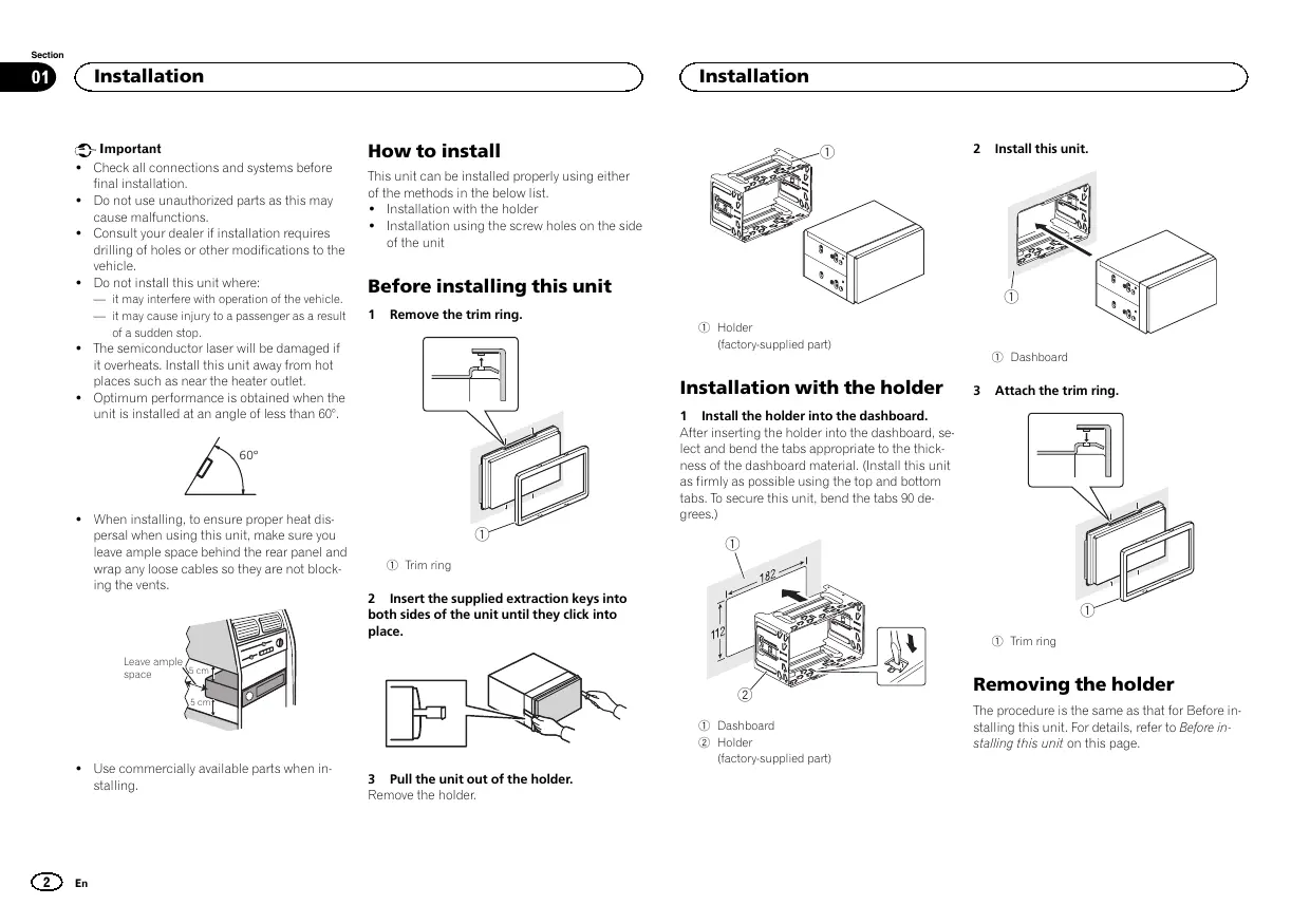
How to install
This unit can be installed properly using either of the methods in the below list.
Installation with the holder
- Installation using the screw holes on the side of the unit
Before installing this unit
1 Remove the trim ring.

① Trim ring
2 Insert the supplied extraction keys into both sides of the unit until they click into place.

3 Pull the unit out of the holder.
Remove the holder.
Installation

① Holder
(factory-supplied part)
Installation with the holder
1 Install the holder into the dashboard. After inserting the holder into the dashboard lect and bend the tabs appropriate to the thness of the dashboard material. (Install this as firmly as possible using the top and bottabs.To secure this unit, bend the tabls 90 d grees.)

① Dashboard
② Holder
(factory-supplied part)
2 Install this unit.

① Dashboard
3 Attach the trim ring.

① Trim ring
Removing the holder
The procedure is the same as that for Before installing this unit. For details, refer to Before installing this unit on this page.
Installation
Installation using the screw holes on the side of the unit
- Fastening the unit to the factory radiomounting bracket.
Position the unit so that its screw holes are aligned with the screw holes of the bracket, and tighten the screws at 3 locations on each side.


① If the pawl gets in the way, bend it down.
② Factory radio mounting bracket
③ Truss (5mm× 8mm) screws
④ Dashboard or console
Connections

Important
- When installing this unit in a vehicle without an ACC (accessory) position on the ignition switch, failure to connect the red cable to the terminal that detects operation of the ignition key may result in battery drain.

ACC position

No ACC position
- Use of this unit in conditions other than the following could result in fire or malfunction.
Vehicles with a 12-volt battery and negative grounding.
— Speakers with 50 W (output value) and 4Ω to 8Ω (impedance value).
-
To prevent a short-circuit, overheating or malfunction, be sure to follow the directions below.
-
Disconnect the negative terminal of the battery before installation.
- Secure the wiring with cable clamps or adhesive tape. Wrap adhesive tape around wiring that comes into contact with metal parts to protect the wiring.
- Place all cables away from moving parts, such as the shift lever and seat rails.
- Place all cables away from hot places, such as near the heater outlet.
- Do not connect the yellow cable to the battery by passing it through the hole to the engine compartment.
Cover any disconnected cable connectors with insulating tape.
Do not shorten any cables. -
Never cut the insulation of the power cable of this unit in order to share the power with other devices. The current capacity of the cable is limited.
Use a fuse of the rating prescribed. -
Never wire the negative speaker cable directly to ground.
-
Never band together negative cables of multiple speakers.
-
When this unit is on, control signals are sent through the blue/white cable. Connect this cable to the system remote control of an external power amp or the vehicle's auto-antenna relay control terminal (max. 300mA 12VDC). If the vehicle is equipped with a glass antenna, connect it to the antenna booster power supply terminal.
- Never connect the blue/white cable to the power terminal of an external power amp. Also, never connect it to the power terminal of the auto antenna. Doing so may result in battery drain or a malfunction.
- The black cable is ground. Ground cables for this unit and other equipment (especially, high-current products such as power amps) must be wired separately. If they are not, an accidental detachment may result in a fire or malfunction.
This unit

① Power cord input
② Microphone input
3 Microphone 4m
④ Rear output or subwoofer output
⑤ Front output
Connections
⑥ Antenna input
⑦ Fuse(10A)
⑧ Wired remote input
Hard-wired remote control adapter can be connected (sold separately).

Power cord
① To power cord input
② Depending on the kind of vehicle, the function of ③ and ⑤ may be different. In this case, be sure to connect ④ to ⑤ and ⑥ to ③
③ Yellow
Back-up (or accessory)
④ Yellow
Connect to the constant 12 V supply terminal.
⑤ Red
Accessory (or back-up)
⑥ Red
Connect to terminal controlled by ignition switch (12 V DC).
⑦ Connect leads of the same color to each other.
⑧ Black (chassis ground)
⑨ Blue/white
The pin position of the ISO connector will differ depending on the type of vehicle. Connect 9 and 11 when Pin 5 is an antenna control type. In another type of vehicle, never connect 9 and 11.
10 Blue/white
Connect to system control terminal of the power amp (max. 300 mA 12V DC).
1 Blue/white
Connect to auto-antenna relay control terminal (max. 300 mA 12V DC).
12 Speaker leads
White: Front left
White/black: Front left
Gray: Front right
Gray/black: Front right
Green: Rear left or subwoofer
Green/black: Rear left or subwoofer
Violet: Rear right or subwoofer
Violet/black: Rear right or subwoofer
ISO connector
In some vehicles, the ISO connector may be divided into two. In this case, be sure to connect to both connectors.
Notes
- Change the initial setting of this unit (refer to the operation manual). The subwoofer output of this unit is monaural.
- When using a subwoofer of 70W (2) , be sure to connect the subwoofer to the violet and violet/black leads of this unit. Do not connect anything to the green and green/black leads.
Connections
Power amp (sold separately)
Perform these connections when using the optional amplifier.

① System remote control
Connect to Blue/white cable.
② Power amp (sold separately)
③ Connect with RCA cables (sold separately)
④ To Front output
⑤ Front speaker
⑥ To Rear output or subwoofer output
⑦ Rear speaker or subwoofer
Installing the microphone
CAUTION
It is extremely dangerous to allow the microphone lead to become wound around the steering column or shift lever. Be sure to install the unit in such a way that it will not obstruct driving.
Note
Install the microphone in a position and orientation that will enable it to pick up the voice of the person operating the system.
When installing the microphone on the sun visor
1 Install the microphone on the microphone clip.

① Microphone
② Microphone clip
2 Install the microphone clip on the sun visor.
With the sun visor up, install the microphone clip. (Lowering the sun visor reduces the voice recognition rate.)

① Microphone clip
② Clamp
Use separately sold clamps to secure the lead where necessary inside the vehicle.
When installing the microphone on the steering column
1 Install the microphone on the microphone clip.

① Microphone
② Microphone base
③ Microphone clip
④ Fit the microphone lead into the groove.
- Microphone can be installed without using microphone clip. In this case, detach the microphone base from the microphone clip. To detach the microphone base from the microphone clip, slide the microphone base.
Installing the microphone
2 Install the microphone clip on the steering column.


① Double-sided tape
② Install the microphone clip on the rear side of the steering column.
③ Clamp
Use separately sold clamps to secure the lead where necessary inside the vehicle.
Adjusting the microphone angle

The microphone angle can be adjusted.
Installation

Important
Retireez le support.
Installation

① Support (piece fourie)
2 Installez cet apparéil.

① Tableau de bord
① Microphone
② Clip microphone
2 BCTaBbTe pinnaraeMbIe kctpaKTopblc 6oEnx CTOpOH yCtpoiCTBa Do uenka.

3 N3BJIeKInTe yCtpoIcTBo n3 KpOHJTeHa. CHMIMTe KpOHJTeH.

① KpoHHTeHH
(BXODNT B KOMNJIeKT NIOCTaBKn)
YctaHOBKa C KPOHHTeHOM
1 UctahOBInTe KpOHNTeHn Ha npri6OpHyo naHEnb.
Iocne yctahOBkn KpOHTeHa Ha npB6OpHyo naHEnb Bb6BePte NoDxOaJIe NfKcATOpbl, nCXODa I3 TOnUINbI MaTePNaIa NpB6OpHoi naHEni, nNoDTOHTE HX. (C NOMOJIb BOEpxHHN uNHKHX NfKcATOpob 3aKpENITE DaHHOy cTPOICTBO KAK MOHNO HAdEeHHe. INa HAdEeHON fNkCaUNY tycPOITBa Heo6OdMIO noDoTHy b fNkCaTOpbl Ha 90 rpaDycob.)

①Пибогнаяпань
2KoHtIe8 (BxOHTB KOMJIENKT NOCTABK)
2 YctaHOBnTe yCTpoIcTBO.

YctaHOBka
① Pπiδopnna nαην
3 YctaHOBNTe paMKy.

①Декашная рамka
N3BLeueHne KpoHsTeHa
Iopraok deiCTBn tot Jx, yTO nepej ycTaHOB- Ky UcTPOiCTBa. IOpO6Hee CM. B pazene Ipej ycTAHOKo DaHHoro YcTPOiCTBa Ha cTp.26.
YCTaHOBka C NOMOuIbpe3b6OBbIX OTBepCTnHa6OKOBbIX naHEnJx YcTpoiCTBa
KpnlenHe yctpOCTBa h 3aBODCKOYtAHOBOHy KPOHHTeN.
PacnoJoknite yctpoCTBO tAKIM o6pa3OM, CTO6bl erO pe3b6BObBe OTBePTN COBnAdanC pe3b6BObMn OTBePTNMA KPOHwTeHa, N 3aTAHnTE No 3 BnHTA H KaKDoI CTOpOE.


① ΠΟΥθΟΝΙΜΕ θΑχμΜ, εςηύ ΜΜεμαετ ΚγατανόΒεκ.
② 3aBODcKOYyCTaHOBOHbI KPOHHTeH
③ Kpeηχhbie(5MM×8MM)BnHTbI
④ Pπb6opHnnaHEnb nJIN KOHcOJIb
CoeHHenH

BaxHo
- PnU yCTaHOBKe DAHORO UcTPOiCTBa V ABOtMO6JIe, B K TOPoR M OTCyTbETyNET NOIooXeHMe KIOHa 3aZKIIrAHH ACC,KpAchN Ka6eNB DOJIKeH 6bITb NODKIOHEn K KIeMME, KOToPAJ ONPeDEHReT paboOee NOIooXeHne KIOHa 3aZKIIrAHH; B nPOTINBOM CJIyuae MOKeT B03NIKKHyTB YTEKA TOKA AKKYMuYTA TOpHoi 6batape.

Пложхене ACC

PIONKENHE ACCOTCYCTBYET
3KcNpIyataaIaDHHORO yCTPOHCTBA B YCNOB8X,OTNIHbIX OT ONICAHBHIX NHXE,MOKET npMBeCTN K NOkApI NYn C6IO B paObe TcPOHCTBA.
TAPNCHONTHBE CPECTBA C 12-BOJbTOBbIM AKKyMnyTOpOM N3aemJIeHnEM OTpuIaTeBbHO NOJIOCA.
- Гамбогоровский 50ВТ (вухидан мочьта) u ot 4Д ог 8Д (conpotroнлеси).
Bo 36EkaHIme KOPOTKOrO 3aMbKAnHn, nepeRpeBa HIN HeNcnpBACHeTc O6aTaTe bHo c6bIouJaTRe CneDyUoJe KyAazAHn.
- Nepet yedahabOKB oOcoBDHnITE OTPaIeTbNHyIO KNEMMY AKKYMNTOPA.
3akpenTe npoBa npn NMOOz 3aKIMOB INI INOJIUMHOIN JENTb. IJN 3aUHTb npoBOKI 3aN3OIOUPyTE npoBOA B MecTAX INX COpNIKOCHOBENI C MToJIINHECKMN DeTALMMI.
PazmectnTe BCE KaBenB ydaenHn OT noD-BHXbIX detaeN, TAKXK KAK pHaar nepeKNoUeHn nepedau Hnapablaoune CndENHn.
PaeMaTeTBE CBe Ka6BnU B ydaNeHnO NT HaRpeBaIOuXNCaDeTaN, TAKNX KAK peWetKa oBorpeBaTeN.
CoeinnHeHn
- UcpHbI Ka6enB JaIpaTeC3a3emJIoUIM. 3a3eMnJIOuIe Kae6enI DaHOrO YcTpoICTBa I npDyIcx YcPoIeTB (OCo6eHNo YcTpoIeTB, npeDaHa3eHbIX DAn 4KcNpIyTaUIm pRi 60JIbIXx ToKax, TaKnx KaK yCunIteB MoUH HcTo) DOJIbXbI MOHTnpOBaTbCr OTeJIbHO. B POnTbHM cIpyae IHc CnyauHoe OTCoeI dHeHneMoKet pINBeCTN K NOxApA NyI IN HeICnPabHocTn.

Даанноустов
① THe3do shHpya nHTaHn
② BXoMnKpOΦoHa
③ Minkpofoh 4M
④ BbXo3dazHeroKananaHIIbXoDcSa6By-4epa
⑤ PerednBbIXoD
⑥ Θhe3dO aHTeHHbl
⑦ Плавский п体现在хашитейь (10 A)
BxOJ npOBoHOro nIyIbTa nICTaHcMOHOro ynpABNeHN
CnykntI nndoNIOHEnH npOBOHOro aadTepa nybTa dctanHIOHOHOro npAbaHNHe (npNOBpTaetcT oTdEBHo).
UHyp nHTaHn

① K rhe3dy uHypa nHTAHNA
2B 3A B3C M C O T N T A B A T O M B I N A D F H K U N I E M O YT OTN H A T B C B. E T O M C P L Y A E C H E Y T N O D K H N O W T B. K I S N K K
③ KeTbI
PesebpBnpaBem (HnPaBem DOnOpHIn-TebnHObO6OpDabHa)
④ KeTbI
ПлкнчiteК Кнелмп ectOун��а noctoанHoroToK 12B.
⑤ KpacHbI
Pazbem DononNHITeHbORo 6OpDyBaHnA H (Ipu p3ePBHybI pa3BpE)
⑥ KpacHbI
PQKIOHHTE K KNEMMe,Ha KOToTpyo NDoaETCn HaprrKeHn (12 B NoctOTHNHO ToKa)PmIKBIOUHn 3zXnHnA.
Плобс麋MнITE npOBODa OДИнAKOBORO ;
乙ета дгук Д耗у.
⑧ YephB(3a3eMnHHeHaMACcy)
CoeHHenHn
⑨ CnHn/6eJIbI
PaclonoxeHne Wtkepea pa3bema ISO ha pa3nHbIX abTOMobmX MoKET OTNIaHbCTc. EcnI WtkePe 5 nepdHa3naHen JIy npAbeHHa ANTHHO, NOCDoEHNHTte 9 K
11.Ha dpynx ABTOM6bnx NpOKnHouBa 9
K 11 aanepeaetc.
10 CnHn/6eBbI
PIONEER ELECTRONICS (USA) INC.
P.O.Box 1540, Long Beach, California 90801-1540,U.S.A.
TEL: (800) 421-1404
PIONEER ELECTRONICS OF CANADA, INC.
340 Ferrier Street, Unit 2, Markham, Ontario L3R 2Z5, Canada
TEL: 1-877-283-5901
TEL: 905-479-4411
PIONEER ELECTRONICS ASIACENTRE PTE. LTD.
253 Alexandra Road, #04-01, Singapore 159936
TEL: 65-6472-7555
PIONEER ELECTRONICS AUSTRALIA PTY. LTD.
5 Arco Lane, Heatherton, Victoria, 3202 Australia
TEL: (03) 9586-6300
PIONEER ELECTRONICS DE MEXICO, S.A. de C.V.
Blvd. Manuel Avila Camacho 138 10 piso
Col.Lomas de Chapultepec, Mexico, D.F. 11000
TEL: 55-9178-4270
先锋股份有限公司
台北市內湖區瑞光路407號8樓
電話:886-(0)2-2657-3588
先鋒電子(香港)有限公司
香港九龍長沙灣道909號5樓
電話:852-2848-6488