FP260 - Fingerprint reader CONRAD - Free user manual and instructions
Find the device manual for free FP260 CONRAD in PDF.


User questions about FP260 CONRAD
0 question about this device. Answer the ones you know or ask your own.
Ask a new question about this device
Download the instructions for your Fingerprint reader in PDF format for free! Find your manual FP260 - CONRAD and take your electronic device back in hand. On this page are published all the documents necessary for the use of your device. FP260 by CONRAD.
USER MANUAL FP260 CONRAD
Copyright 2008 by Conrad Electronic SE.
GB Legal notice
These operating instructions are a publication by Conrad Electronic SE, Klaus-Conrad-Str. 1, D-92240 Hirschau (www.conrad.com).
All rights including translation reserved. Reproduction by any method, e.g. photocopy, microfilming, or the capture in electronic data processing systems require the prior written approval by the editor. Reprinting, also in part, is prohibited.
These operating instructions represent the technical status at the time of printing. Changes in technology and equipment reserved.
Copyright 2008 by Conrad Electronic SE.
Information legales
© Copyright 2008 by Conrad Electronic SE.
NL Colofon
© Copyright 2008 by Conrad Electronic SE.
Version 12/08
CE
Fingerprintmodul FP260
Seite 3 - 8
GB Fingerprint Module FP260
Page 9-14
These operating instructions belong with this product. They contain important information for putting it into service and operating it. This should be noted also when this product is passed on to a third party.
Therefore look after these operating instructions for future reference!

(LxBxH) ca.60mmx54mmx33mm
(LxBxH) ca.80mmx80mmx48mm
Intended use
The fingerprint module servers as personal access system for the most varied applications.
It enables access control to various systems via the unique fingerprint of up to 25 authorized persons.
The fingerprint is read via the module and if it coincides with one of the authorized persons, a potential-free switching output is activated.
Up to 25 fingerprints can be programmed and deleted/changed in the fingerprint module.
The module is supplied via a direct current source of 12V or an alternate current source of 8V .
The maximum load on the switching output is 35 VDC/AC and 3 A.
It is not permitted to switch machines or devices with the module, which may cause bodily harm or mortal danger.
The reader module is designed for installation in a standard electric wall outlet but can also be mounted on the wall with the enclosed installation ring. Both modules have to be protected from penetrating water (rain) or excess dew. The required safety regulations concerning the safety distance to live voltages/cables have to be observed.
The module has a serial interface (RS232) for connection to a PC. Using this, a connection to the supplied FP260 PC software can be established.
No part of the product may be modified or converted. The safety instructions must be observed.
Safety instructions and hazard warnings

Please read through the operating instructions completely before using the product for the first time; they include important information necessary for correct operation.
- The guarantee will be rendered null and void if damage is caused as a result of failure to observe the operating instructions. We will not assume any responsibility for consequential damage.
- We shall not accept liability for damage to property or personal injury caused by incorrect handling or non-compliance with the safety instructions! The warranty will be rendered null and void in such cases.
- This device is not a toy and should be kept out of reach of children.
- The module has been CE-tested and meets the necessary European guidelines.
- Only an expert may install the device.
Installation and connection
The module is delivered completely assembled and must only be connected via the cable 4^ (observe the direction snaps). For programming, remove the cover of the evaluation unit by slightly pressing on the latches on the side (V).

When installing the device, makesure that the eval-uation unit that contains the two jumpers ^ 1^ and ^ 5^ is not accessible for unauthorized persons (e.g. separation by a wall), as this is required to delete and program the fingerprints. The jumpers ^ 2^ ,^ 3^ and ^ 4^ may not be bridged and you may not attach any connections (production connection).
Install the two units at the desired location. The distance between the evaluation unit and the sensor unit is at most 50~cm . Extensions are not permitted.
The fingerprint module can control a door opener, for example. Connect the door opener etc. to the two clamps of the potential-free switching output K2^ .
Carefully tighten the screws with a matching screwdriver.
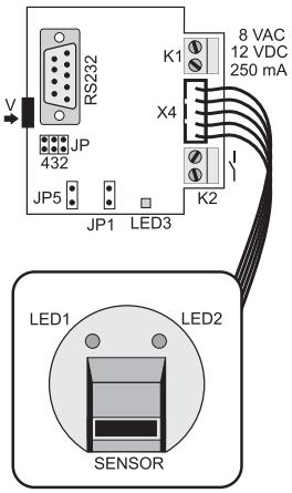
Connect the fingerprint module with a suitable voltage source. A suitable voltage source provides a stable output voltage of 8 VAC or 12 VDC at 250mA min.
Connect the voltage source to the screw clamp „K1“ while the power is off. Carefully tighten the screws with a matching screwdriver.
You do not have to observe the polarity. Check all plug and screw connections once again for tight fit.
The fingerprint module is ready for use.
Initial operation
Remove the bridge on jumpers "JP1" and "JP5".
After successful installation and connection of the fingerprint module, you can now turn on the power supply of the evaluation unit.
The displays "LED1", "LED2" and "LED3" light up. "LED3" goes off after approx. 10 s. During this starting time, the system is checked internally. The fingerprint module is ready for use.
Programming the authorized fingerprints

Always use the same finger (the index finger is ideal) for the memory and test process and position it the same way, centrally above the sensor, otherwise the system will not accept it. Perform all operating steps without longer breaks; otherwise the process is interrupted automatically, ignored, or the device can only be returned to normal operating mode with a hardware reset (see „Hardware Reset") to protect the device from manipulation.
General information
If the LED status does not change when programming or recording the fingerprint, pull the finger over the sensor once again.
An accidental double blink of „LED1“ and „LED2“, without your interference, is system-related and has no influence on the function.
Master fingerprint
Before you program the persons with authorized access, you first have to program a master fingerprint. Later memory procedures can only be initiated with the master fingerprint. The first memorized fingerprint is automatically defined as master.
To program the master fingerprint, proceed as follows:
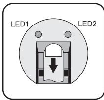
- Apply the operating voltage to "K1" (if you haven't already done so); "LED1" and "LED2" must light up!
- Plug the bridge onto jumper "JP1". After approx. 10 s, "LED2" goes out and "LED3" light up.
- Position the desired finger as illustrated in the sensorcasing until you hit the stop.
- Pull the finger evenly across the sensor. Slightly press down your finger in this process so that it touches the two metal strips on the top and bottom end of the sensor simultaneously. This procedure should take no less and no more than approx. 1 second. If the fingerprint was memorized correctly, "LED1" goes off and "LED2" lights up.
- Position the same finger once again in the sensor casing until you hit the stop.
- Pull the finger out evenly over the sensor. This procedure should take no less and no more than approx. 1 second. If the 2nd fingerprint was memorized successfully, "LED1" lights up in addition to "LED2".
- Position the same finger for the third time in the sensor casing until you hit the stop.
- Pull the finger out evenly over the sensor. This procedure should take no less and no more than approx. 1 second. If the fingerprint was memorized correctly, LED1^a and LED2^a go off. They flash briefly once again.
- "LED2" lights up after approx. 2 seconds.
- Pull the bridge off on jumper "JP1". After approx. 30 s, your information is computed and encoded. "LED1" and "LED2" light up. The master memory procedure is completed.
Now check whether the reading unit recognizes your master fingerprint. To do so, insert the just memorized master finger into the sensor until you hit the stop. _LED2" goes off. Pull the finger out evenly. _LED1" goes off as well. After approx. 1 s, the relay kicks in for approx. 2 s. Then _LED1" and _LED2" light up again.
If the unit does not detect the master finger at the 1st or 2nd attempt (the relay does not click), delete the module data as described in „Deleting the memorized fingerprints" and repeat the master fingerprint memory procedure.
User fingerprint
In order to memorize a new user fingerprint, the module first has to detect the master fingerprint successfully.
Once the master fingerprint was detected successfully (section „A”), you can program all other user fingerprints in sequence (section „B").
A To detect the master fingerprint, proceed as follows:
- Plug the bridge onto jumper „JP1“. After approx. 10 s „LED1“ goes off and „LED3“ lights up.
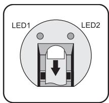
- Position the master finger as illustrated in the sensor casing until you hit the stop.
- Pull the finger out evenly over the sensor. This procedure should take no less and no more than approx. 1 second. If the master fingerprint was successfully scanned, LED2 goes off and LED1 blinks briefly. Then LED 1 blinks to indicate that the system is ready to scan additional user fingerprints.
B To memorize the user fingerprints, proceed as follows:
- Position the desired finger as illustrated in the sensor casing until you hit the stop.
- Pull the finger out evenly over the sensor. This procedure should take no less and no more than approx. 1 second. If the fingerprint was memorized correctly, "LED1" goes off and "LED2" lights up.
- Position the same finger once again in the sensor casing until you hit the stop.
- Pull the finger out evenly over the sensor. This procedure should take no less and no more than approx. 1 second. If the 2nd fingerprint was memorized correctly, LED1^ and LED2^ are lit.
- Position the same finger for the third time in the sensor casing until you hit the stop.
- Pull the finger out evenly over the sensor. If the fingerprint was memorized correctly, "LED1" and "LED2" go off. They flash briefly once again.
- "LED1" lights up after approx. 2 seconds. This confirms proper memorizing.
Perform this procedure as of section ^ Point 1 - 7 for all further fingerprints to be memorized.
- Pull the bridge off on jumper "JP1". After approx. 30 s, your information is computed and encoded. "LED1" and "LED2" light up. The user memory procedure is completed. The device is ready for operation. Replace the cover of the evaluation unit.

If the memory process is acknowledged by 5 × double blinking of „LED1“ and „LED2“, the data memory is full. Then it is not possible to memorize another fingerprint.
Never forget to pull the bridge off of jumper „JP1“ after each memory process.
Operation
In normal operating mode, the two jumpers "JP1" and "JP5" may not be plugged.
,LED1" and ,LED2" are lit (the control LED ,LED3" is off in this mode).
For operation, proceed as follows:
- Position the corresponding finger as usual in the sensor casing until you hit the stop. "LED2" goes off.
- Pull the finger out evenly over the sensor. This procedure should take no less and no more than approx. 1 second. "LED1" goes off right afterwards.
- If a fingerprint was detected successfully, the switching contact is activated for approx. 2 seconds.
- "LED1" and "LED2" light up again.
- The module is ready for the next detection.
Error message of LED1 and LED2 / fingerprint was not detected
If the fingerprint was not detected during a detection attempt (insufficient data), only „LED2“ goes off. If another read attempt does not turn „LED1“ off (insufficient data), „LED1“ and „LED2“ signal this at latest after 10 s by blinking 3 times.
The reason may be the too fast or too slow reading process, an unauthorized fingerprint or a failed fingerprint reading. If applicable, clean the sensor surface with a soft, antistatic cloth.
Repeat the reading process again when the two LEDs (LED1^ and LED2^ ) are lit again.

A short flickering of „LED1“ and „LED2“ during normal operation is system-related and does not indicate a defect (e.g. loose connection or similar).
Deleting the memorized fingerprints
The memorized fingerprints can only be deleted altogether. Individual deletion is not possible.
To delete all fingerprints (the master as well), proceed as follows:
- If applicable, remove all jumpers from the main circuit board.
- Put the bridge onto jumper „JP5“ and wait approx. 20 seconds until „LED2“ lights up.
- After this time (and not before), all memorized fingerprints are deleted.
- Pull the bridge off of jumper „JP5". The module can be programmed with new fingerprints.
Hardware Reset
If „LED1“ and „LED2“ do not show any reaction to touching the sensor caused by external influence like voltage peaks, wrong operation or forgetting to pull of the jumpers, the operating voltage has to be interrupted at the clamp „K1“ for 20 seconds.
The memorized fingerprint data is preserved.
RS232 interface / PC software
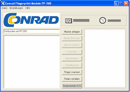
The fingerprint module has a serial interface. Via this interface, a data connection to a PC can be established using a 9-pin 1:1 RS232 cable (plug-socket). To this end, the FP260 PC software is supplied. It provides numerous additional functions for simpler operation of the system and management of the fingerprints.

Please read the instructions on the FP260 software CD.
Disposal

Old electronic devices are hazardous waste and should not be disposed of in household waste. When the device has become unusable, dispose of it in accordance with the current statutory regulations at the communal collection points. Disposal in the household waste is prohibited.
Technical data
Operating voltage 12 VDC/8VAC
Current consumption max. 180mA standby ca. 20mA
Possible fingerprints (depending on size). 15-25 (incl. master)
Switching output relay: 35 V AC/DC / 3 A
Switching time relay: ca. 2s
Length of the connection cable. Approximately 50 cm
Interface RS232
Weight (without installation adapter) . . . Approximately 105g
Dimensions evaluation unit
(LxWxH) approx. 60 mm x 54 mm x 33 mm
Dimensions sensor unit
(LxWxH) approx. 80mm× 80mm× 48mm