POWER PEAK ULTIMATE - Battery charger ROBBE - Free user manual and instructions
Find the device manual for free POWER PEAK ULTIMATE ROBBE in PDF.

| Product type | Battery charger |
| Brand | ROBBE |
| Model | POWER PEAK ULTIMATE |
| Power supply voltage | 10-15 V DC (12 V battery or stabilized mains unit) |
| Max. input current | 14 A |
| Compatible battery types | Ni-Cd, NiMH, Lead (Pb) |
| Number of cells | 1 to 25 for Ni-Cd/NiMH, 2-12 V for Lead |
| Charge current | 0.1 A to 5 A (depending on configuration) |
| Discharge current | 0.1 A to 3.0 A |
| Charge/discharge modes | Automatic and Manual |
| End-of-charge detection | Delta-Peak (Ni-Cd/NiMH), constant voltage (Lead) |
| Parameter memory | 10 slots |
| Dimensions | 125 × 165 × 60 mm |
| Protections | Input/output polarity reversal, output short circuit, overheating, undervoltage |
| Display | Backlit LCD screen |
| Display languages | German, English (selectable at startup) |
| Maintenance | Clean with a dry cloth, avoid moisture |
| Safety | Do not cover, allow to cool, observe polarity |
| Included accessories | Alligator clips, charge cable, ferrite core |
| Optional mains power supply | Power Peak 7A (ref. 8415) |
Frequently Asked Questions - POWER PEAK ULTIMATE ROBBE
User questions about POWER PEAK ULTIMATE ROBBE
0 question about this device. Answer the ones you know or ask your own.
Ask a new question about this device
Download the instructions for your Battery charger in PDF format for free! Find your manual POWER PEAK ULTIMATE - ROBBE and take your electronic device back in hand. On this page are published all the documents necessary for the use of your device. POWER PEAK ULTIMATE by ROBBE.
USER MANUAL POWER PEAK ULTIMATE ROBBE
The POWER PEAK ULTIMATE is designed for charging and discharging NICD and NIMH batteries consisting of 1 to 25 cells, both in automatic mode with automatic current setting, and in manual mode. The charge process is terminated by the Delta Peak method when the battery is fully charged.
The unit can also charge lead-acid batteries (2 to 12 Volts) automatically.
The charger features 10 spot memories in which you can store settings which you have entered for each battery in manual mode.
Safety notes
- If the charger is not to be used for a protracted period, disconnect it from the power source and remove any battery packs connected to it.
- Be sure to keep the cooling slots unobstructed to provide good air circulation - don't stand the charger on a carpet or felt surface.
- Do not set up the charger and batteries on a flammable surface, and never leave the unit operating unsupervised.
- Protect the unit from damp.
Take care to maintain correct polarity at all connections and outputs. - Avoid short-circuits.
- Don't subject the charger to direct sunshine, and do not cover it.
- Do not charge batteries which are already hot; allow them to cool down to ambient temperature before recharging.
- Use only packs of fast-charge cells which have been properly balanced (equal state of charge).
- Packs must consist of cells of the same make, type and capacity.
- Do not wire two packs together in parallel for charging.
- The unit is only suitable for use with rechargeable batteries.
- Set charge currents within the maximum rated capacity of the cables and connectors attached to the battery pack.
- Never connect any charger output to the input.
Specification
| Operating voltage: | approx. 10 V ... 15 V DC 12 V lead-acid battery or a powerful well stabilised mains PSU (do not use a car battery charger!) | |||
| Current drain: | max. approx. 14 A | |||
| Nominal battery voltage: | 1.2 V ... 30.0 V (1 ... 25 NICD / NIMH cells, 2V ... 12 V lead-acid) | |||
| Fast-charge current | 0.1 ... 5 A, voltage-dependent; see table (approximate values) | |||
| 3V | 6V | 9V to 20V | 40V | |
| max: | 2A | 3A | 5A | 3A |
| Trickle charge current: | none |
| Automatic charge termination: | Delta Peak process / lead-acid process |
| Discharge termination: | automatic, at approx. 0.8 V / cell (NICD and NIMH only) |
Max. discharge power: approx. 20 W
Discharge current: 0.5 A ... 3.0 A
Protective functions: Polarity protection at input and output, short-circuit protection on output, overheating protection, low voltage protection, excess voltage protection
Dimensions: approx. 125 × 155 × 80 mm
Charger controls
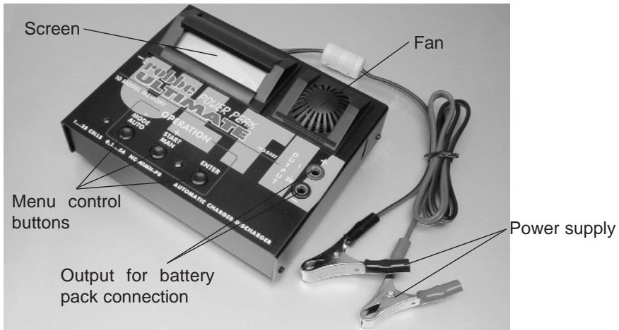
Using the charger
- Connect the crocodile clips to a 12 ~V lead-acid battery or a suitable mains PSU; take great care over correct polarity (red = positive / black = negative).
- The LCD screen will show "AUSWAHL MODUS / AUTOMAT/MANUELL" or "MODE SELECT / AUTOMATIC/MANUAL".
- Selecting the language: To change the language hold the ENTER button pressed in while you connect the power supply; a Language Select menu will appear. You can switch between DEUTSCH (German) and ENGLISH by pressing the - or + button. Change the setting to the language of your choice.
- Connect the battery charge leads to the OUTPUT sockets (red = positive / black = negative).
- Connect the battery pack to the charge leads with correct polarity.
- The charger is now ready for use.
- Press the MAN or AUTO button to switch between manual and automatic charge and discharge.
AUTOMATIC MODE
The charger selects the optimum current and voltage values.
CHARGE
START
NICD AUTO.
MODE
If you press the MODE button repeatedly you can switch between CHARGE, DISCHARGE and DISC/CHAR for NICD and NIMH packs separately.
- Press the START button to initiate the selected process.
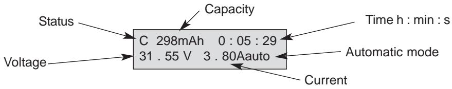
- The screen displays capacity, time, voltage and current. The status (C=CHARGE, D=DISCHARGE, F=FINISHED) is displayed at top left of the screen.
- The charge or discharge process is ended by the automatic termination circuit or by the operator pressing the STOP button.
MANUAL MODE
Before you can start the actual charge or discharge process, you have to set the battery type (NICD, NIMH or PB), the cell count, the battery capacity, the charge current and the discharge current.
Up to ten such sets of parameters can be stored in spot memories 0 to 9 and called up at any time. The setup menu required for this appears immediately when you select manual mode.
Note: you can only change values in the first line when the arrow symbol is flashing.
MEMORY SELECT 0<-BAT.TYPE NICD
Selecting the spot memory: Select the MEMORY SELECT menu with the + button, confirm with ENTER, select the desired spot memory with the +/- buttons and confirm with ENTER. See also the section "Selecting a spot memory".
BAT.TYPE NICD<- BAT.CELL. 21 CELL
Selecting the battery type: Select BAT.TYPE with the + button, select the type with ENTER.
BAT. CELL. 21 CELL<- BAT.CAP. 1800mAh
Entering the cell count: press the + button to select BAT. CELL, confirm with ENTER. Set the cell count with the +/- buttons and confirm with ENTER.
BAT. CAP. 1800mAh<-CHAR.CUR. 4.5 A
Entering the battery capacity (BAT. CAP): same method as entering the cell count.
CHAR.CUR. 4.5A<- DISC.CUR. 2.5 A
Entering the charge current (CHAR. CUR.): same method as entering the cell count.
DISC. CUR. 2.5 A<-EXIT
Entering the discharge current (DISC. CUR.): same method as entering the cell count (PB: not available).
EXIT
SOUND
一
OFF
START
<--
MEMORY SELECT
0
CHARGE
START
0]NICD 21CL
1800
Spot memory
C 298mAh 0:05:29
31.55V 3.80A
At the EXIT menu point you can jump to the "AUTO / MANUAL" select option with the ENTER button; under SOUND press the ENTER button to activate or disable the buzzer.
To initiate the charge or discharge process confirm the START menu point with the ENTER button.
You can now press the MODE button to select CHARGE, DISCHARGE or DISC-CHAR.
Start the charge or discharge process by pressing the START button.
The screen displays capacity, time, voltage and current. The charger's status (C=CHARGE, D=DISCHARGE, F=FINISHED) is displayed at top left of the screen.
- The charge or discharge process is ended by the automatic termination circuit or by the operator pressing the STOP button.
- When you next connect the charger to its power supply, the unit automatically reverts to the spot memory you last used.
Auxiliary functions
Adjusting the current during charging or discharging (manual mode only)
CHARGE CURRENT
4.5A
DISCHARGE CUR.
2.5A
Use the + / - buttons to change the current during charging or discharging.
Additional information
Access via double button function (press + and - buttons simultaneously); leaf through with the + or - buttons.
IN/OUT VOLTAGE
Input and output voltage
Peak and momentary voltage
Discharge voltage at start or end of the discharge process.
CHAR. 1990mAh DISC. 1720mAh
CHAR. 0:17:35
DISC. 1:47:21
0]NICD 21 CL 1800 C:4.5A D:2.5A
Charged-in or discharged capacity
Charge or discharge time
Spot memory, cell count, capacity, charge current and discharge current
Error messages
The following error messages can be erased by pressing any button once you have eliminated the problem.
+++OVERLOAD ++++
+++PROTECT +++
Charger overloaded; allow to cool down.
Power supply voltage less than about 9.5 V.
OUTPUT BATTERY CONNECT ERROR
Check connection between battery pack and charger.
OUTPUT BATTERY REVERSE POLARITY
Battery connected with reverse polarity; check connections.
OUTPUT BATTERY SHORT CIRCUIT
Short-circuit at charger output; check connections.
OUTPUT BATTERY LOW VOLTAGE
Battery pack voltage too low; check cell count setting.
OUTPUT BATTERY OVER VOLTAGE
Battery pack voltage too high; check cell count setting.
Input voltage higher than about 15.5V
TEMPERATURE SENSOR ERROR
Problem with temperature sensor. If this error recurs, consult the robbe Service Department.
EEPROM WRITING ERROR
Problem with internal memory. If the problem recurs, consult the robbe Service Centre.
Selecting a particular spot memory in which you have stored data
- Select "Manual" with the "MAN" button.
- Select MEMORY SELECT with the "+" button.
- Press the "ENTER" button.
- Select the desired spot memory with the "+" or "-" button.
- Confirm with the "ENTER" button.
- Select "START" with the "-" button.
- Confirm with the "ENTER" button.
- If necessary change mode to CHARGE or DISCHARGE and DISC-CHAR using the Mode button.
- Start the process by operating the "START" button.
General information about charging and discharging batteries
As a basic rule please be sure to observe the battery manufacturer's recommendations, especially the information regarding maximum charge currents.
To ensure that the automatic Delta Peak circuit is able to work as efficiently as possible, only properly balanced packs should be fast-charged. This means that new packs, and packs which have not been used for a long time, should be discharged at regular intervals and re-balanced by slow-charging at a low rate, typically C/10.
An occasional complete discharge process also helps to avoid and/or eliminate the MEMORY EFFECT.
Fairly old batteries, and packs of certain relatively low-quality cells, may prevent the automatic current setting function working properly in automatic mode. In such cases we recommend that you use manual mode.
Charging and discharging a transmitter battery which is installed in the RC system transmitter is only possible if you either by-pass the protective diode in the transmitter's charge circuit, or remove the battery from the transmitter and connect it to the charger using a direct charge lead.
Conversion work on the transmitter should only be carried out by an expert, ideally by your nearest robbe Service Centre.
Recommended direct charge leads
No. 8262
F-series transmitter
No. 8263
International series
Notes
- The maximum charge and discharge currents vary according to the number of cells in the pack.
- Don't end the charge or discharge process simply by disconnecting the battery pack; always stop the process by pressing the MODE button.
- Lead-acid batteries can only be charged in manual mode.
Mains PSU
- If you use the Power Peak 7A mains PSU, Order No. 8415, the charger can also be operated from the 230 Volts mains supply, turning it into a universal 230 V AC and 12 V DC charger. Note that the maximum currents are restricted in this mode of operation when used with high cell counts.
Notes on RID (Radio Interference Directive)
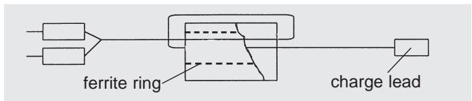
In order to satisfy the conditions of the RID, the charge lead must be modified using the ferrite ring as shown in the sketch before you use the charger for the first time.
We reserve the right to alter technical specifications.
Généralités
m = 311
MEMORY SELECT
0
CHARGE
START
0]NICD 21CL
1800
EEPROM WRITING ERROR