
AWC - Fan APPLIED ENERGY - Free user manual and instructions
Find the device manual for free AWC APPLIED ENERGY in PDF.
| Product type | Speed controller for ceiling fans |
| Brand | APPLIED ENERGY |
| Model | AWC |
| Compatibility | Up to 10 NWAN Whispair Xpelair ceiling fans |
| Main functions | Automatic and manual speed regulation based on temperature difference |
| Included sensors | 2 temperature sensors (10 m and 1 m cables) |
| Operating modes | Automatic and manual |
| Power supply | 230 V ~ 50 Hz (rated voltage as indicated on the housing) |
| Fuse | 6.3 A F rated |
| Mounting | Surface or flush mounting, with supplied metal box |
| Max ambient temperature | 50 °C |
| Max sensor ambient temperature | 35 °C |
| Protection rating | Not specified (indoor use) |
| Box dimensions | Approximately 120 x 80 x 50 mm (estimated) |
| Weight | Approximately 0.3 kg (estimated) |
| Maintenance | Wipe with a damp cloth, do not immerse, do not use solvents |
| Installation | By a qualified electrician, in accordance with IEE regulations |
| Safety | Mandatory earthing, double-pole disconnector with 3 mm contact gap |
| Warranty | Not specified |
| Repairability | Spare parts not mentioned; replaceable fuse |
Frequently Asked Questions - AWC APPLIED ENERGY
User questions about AWC APPLIED ENERGY
0 question about this device. Answer the ones you know or ask your own.
Ask a new question about this device
Download the instructions for your Fan in PDF format for free! Find your manual AWC - APPLIED ENERGY and take your electronic device back in hand. On this page are published all the documents necessary for the use of your device. AWC by APPLIED ENERGY.
USER MANUAL AWC APPLIED ENERGY
Retain for future reference
This appliance is designed to control the operation of Xpelair NWAN Whisper fan range.
It is designed to minimise the temperature differential between high and low levels in large buildings. The unit is supplied with two temperature sensors and can be used to operate up to ten NWAN ceiling sweep fans. The AWC can be operated in either automatic or manual modes.
IN AUTOMATIC MODE:
- If the control knob is set in the fully anticlockwise position, minimum fan speed occurs when the difference in high and low level temperatures is 3^ or less; maximum speed occurs when the difference is 6^ or more.
- If the control knob is set in the fully clockwise position, minimum fan speed occurs when the difference in high and low level temperatures is 10^ or less; maximum speed occurs when the difference is 13^ or more.
- To reduce the temperature difference at which the fan speed will vary, turn the control knob anticlockwise. Increase by turning clockwise.
IN MANUAL MODE:
- To reduce the fan speed, turn the knob anticlockwise. To increase the fan speed, turn it clockwise.
IN AUTOMATIC AND MANUAL MODES:
- The fan comes on automatically at full speed for the first 10 seconds before reverting to the speed selected.
- The AWC can be either surface or recess mounted using the metal wall box supplied.
Installing the Controller
These installation instructions are for the installation of the controller when used in combination with Xpelair supplied fans.

The controller must be installed to fixed wiring. Ensure the Main Electrical Supply matches the rating shown on the controller casing.
THIS APPLIANCE MUST BE EARTHED!
All installation must be supervised by a qualified electrician.
Installation and wiring must conform to current IEE wiring regulations (UK), or local appropriate regulations (other countries).
If you have any queries either before, during or after the installation of the controller, please do not hesitate to contact the UK Xpelair hotline (number on back page). Customers outside UK: contact your local Xpelair distributor.
What the installer will need
- A double pole isolating switch with a minimum contact gap of 3mm (Wall or Ceiling mounted).
- Suitably rated 4-core cable to connect the controller to the fan/s.
- Suitably rated 3-core cable to connect the controller to the Main Electrical Supply.

If using flexible cable, suitable glands incorporating cable clamps must be fitted to the knockouts in the Controller Box.
Refer to Fig 1.
Location of the Controller
- Not where ambient temperatures are likely to exceed 50^
- If installed in a kitchen the Controller must not be mounted immediately above a cooker or eye level grill.
- When intended for use in possible chemical corrosive atmospheres, consult our Technical Service Department (outside the UK contact your local Xpelair distributor)
- If installed in a shower room or bathroom the controller and isolating switch must be situated so that they cannot be touched by persons making use of the bath or shower.
Location of the Sensors
- Not where temperatures exceed 35^ C
- Pointing away from walls or other obstructions, to ensure adequate ventilation.
- High level sensor, above fan mounting height.
- Low level sensor, within 1m of the controller.
- When intended for use in possible chemical corrosive atmospheres, consult our Technical Service Department (Outside the UK contact your local Xpelair distributor)
Working with the Fan

If wiring to an existing installation isolate mains supply and remove applicable fuses prior to any electrical procedure.
If the fan is already installed.
- Ensure the power supply is isolated.
- Disconnect the mains connections from the fan's terminal socket or from the terminal block.
- Remove the existing wiring and make it safe.
If the fan is not already installed.
- Check that the fan electrical rating matches the power supply.
- Mount the fans in accordance with the instructions supplied.
- Route the four core cable from the controller position to each fan.
- Route the three core cable from controller position to the isolator position.
Mounting the Controller
Remove the Cover and Mounting Frame.
- Detach the Fascia from the Mounting Frame by removing the screw covers and two screws (Refer to Fig. 2a & b).
- Detach mounting Frame from the Wall Box by removing the two screws (Refer to Fig. 2c).
- Lift the Wall Box away from the Plastic Surround.
- Check that the electrical rating shown inside the controller matches the power supply.
- Disconnect the earth wire from the Wall Box.
- Make cable entry holes in the plastic and metal boxes by removing suitable knockouts (Refer to Fig. 1).
Mounting the Wall Box

Eye protection must be worn during all drilling and chiselling operations.
Check there are no buried Pipes or Cables in the wall or obstructions on the outside e.g. Electricity, Gas, Water.

If surface mounting
- Insert suitable glands into the knockouts.
- Feed both cables through the glands.
- Fix the Wall Box and Plastic Surround to the wall, using the mounting holes provided.
- Re-connect the earth lead to the Wall Box.
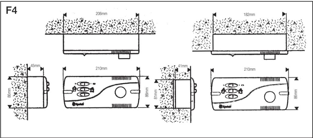
If recess mounting
- Make a hole in the wall big enough to take the Wall Box.
- Insert suitable glands into the knockouts.
- Feed both cables through these glands.
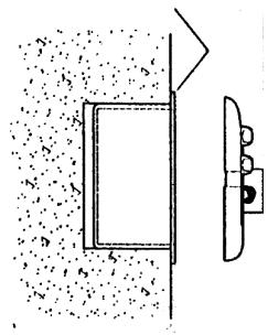
- Fix the Wall Box to the wall. Ensure that the flange of the mounting frame fits flush to the finished surface of the wall (Refer diagram F3.
- Re-connect the earth lead to the Wall Box.
Mounting the Sensors
Using the two clips supplied, mount the temperature sensors horizontally, without touching the walls or ceiling.
- Mount the sensor with the 10m cable in the high level position.
- Mount the sensor with the 1m cable in the low level position suitably protected.
- Install the cables in closed conduits, leaving the other ends ready to wire into the controller.
Wire the Controller electrical connections
- Mount the Isolation Switch in accordance with the manufacturers instructions.
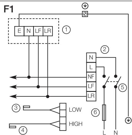
- Wire the Controller to the Isolation Switch and to the Fan as shown in the appropriate diagram F1.
- Connect the sensor cables to the high and low sensor terminals.
- Connect any remaining fans in parallel.
- Refit Mounting Frame to Metal Wall Box.
- Refit the Fascia to the Mounting Frame.
- Refit the Screw Covers.
FUSE 6.3 AMP F RATED
Connect to Power Supply
- Ensure power supply is isolated and fuses are removed.
- Route the Cable from the Isolating Switch to the point of connection to the power supply.
-
Make all connections within the isolating Switch in accordance with the manufacturers instructions.
-
Following all IEE and local regulations make connection at point of power supply.
- Make a final check to ensure all earth points are connected and all covers have been correctly replaced on the fan, controller and isolating switch.
- Replace all fuses, and switch on the power supply.
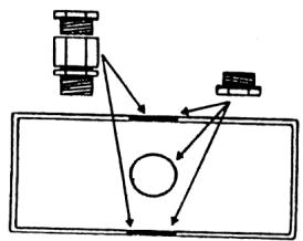
Fig 1. Cable gland positions
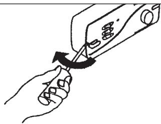
Fig 2a. Removing screw covers
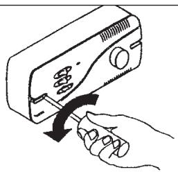
Fig 2b. Removing fascia
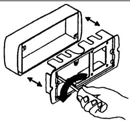
Fig 2c. Removing mounting frame
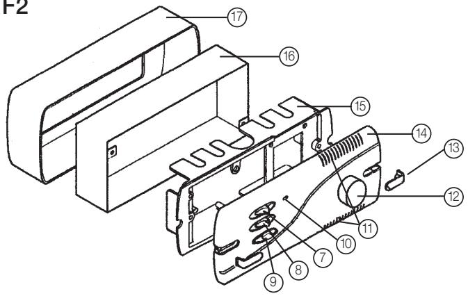
F2
F3
Ensure mounting frame flange fits flush to the wall
F1
1) Fan terminal block
2) Controller terminal block
3) Low sensor
4) High sensor
5) Double pole isolator
6) Fuse (6.3 amp F rated)
F2
7) ON/OFF switch
8) Forward or reverse running
9) Automatic or manual mode
10) Fan running indicator light
11) Ventilation slots
12) Speed/temperature setting
13) Screw cover
14) Fascia
15) Mounting frame
16) Metal wall box
17) Plastic surround
Looking after the controller
CLEANING
- Before cleaning isolate the controller completely from the power supply.
-
Wipe the cover carefully with a damp cloth.
-
Dry thoroughly.
- Ensure ventilation slots are free from obstructions at all times.

- Never immerse the controller in water or other liquids.
- Never use solvents to clean the controller.
- Apart from cleaning, no other maintenance is required.
DIT APPARAAT MOET GEAARD ZIJN!
IN MODALITA MANUALE:
Customers outside UK - see international below.
- The controller is guaranteed against defects for 3 years from the date of purchase.
- Please keep your purchase receipt.
- If you have any problems, contact Xpelair's Head Office at the address shown below.
Technical advice and service (UK)
Customers outside UK - see international below.
UK: Xpelair have a comprehensive range of services including:
- Free technical advice help-desk from Engineers on all aspects of ventilation.
- Free design service, quotations and site surveys.
Service and maintenance contracts to suit all requirements.
Please ask for details:
- By telephone on Techline: +44 (0) 8709 000430
By fax on Techfax: +44 (0) 8709 000530 - At the address below
Head Office, UK Sales Office and Spares
Applied Energy Products Ltd, Morley Way, Peterborough, PE2 9JJ England
Telephone: +44 (0) 1733 456789
Fax: +44 (0) 1733 310606
Sales Hotline: +44 (0) 8709 000420
http://www.xpelair.co.uk
International
- Guarantee: Contact your local distributor or Xpelair direct for details.
- Technical Advice and Service: Contact your local Xpelair distributor.