
LV100 - Fan APPLIED ENERGY - Free user manual and instructions
Find the device manual for free LV100 APPLIED ENERGY in PDF.

User questions about LV100 APPLIED ENERGY
0 question about this device. Answer the ones you know or ask your own.
Ask a new question about this device
Download the instructions for your Fan in PDF format for free! Find your manual LV100 - APPLIED ENERGY and take your electronic device back in hand. On this page are published all the documents necessary for the use of your device. LV100 by APPLIED ENERGY.
USER MANUAL LV100 APPLIED ENERGY
Humidistat and Pull Cord
LV100PIR
Integral Body Movement Sensor
Safety extra low voltage toilet/bathroom 100mm fan range

A
LV100PIR
D
E
Window mounting
B
Wall/panel mounting
F
2
C
1
G
H
LV100, LV100PC, LV100H, LV100HP & LV100PIR
LV100T
J
LV100, LV100PC, LV100H, LV100HP & LV100PIR
LV100T
#
K
LV100H & LV100HP
LV100PIR
M
Xpelair
Toilet/Bathroom
Fans IV100,
IV100PC, IV100T,
IV100H, IV100HP & IV100PIR
installation &
operating
instructions
Please leave this leaflet with the fan for the benefit of the user
Installing the fan
These appliances are intended for connection to fixed wiring.
Check that the electrical rating shown on the transformer matches the mains supply.
THESE APPLIANCES ARE DOUBLE INSULATED AND DO NOT REQUIRE AN EARTH CONNECTION.
All installations must be supervised by a qualified electrician.
Installations and wiring must conform to current IEE Regulations (UK), local or appropriate regulations (other countries).
If you have any queries before installing these products or after they have been installed, call the Xpelair Technical Hotline +44(0) 8709 000430. Our Engineers are there to help you during normal office hours (UK only) and may be faxed at all other times +44(0) 8709 000530.
Customers outside the UK may contact your local Xpelair distributor.
Description
All fans
Universal mounting kit allows Window/Wall/Panel/Ventilation Shaft/Ceiling mounting options. See termination details. If Ceiling mounting the fan, see section 'What the installer will need'.
- Single speed extraction.
12V a.c. operation.
IV100
- Operate the fan using an on/off switch (not supplied).
LV100PC
- Operate the fan using the integral pull cord.
LV100T
- Built-in timer automatically operates fan for a preset delay of up to 25 minutes.
LV100H
- Operates when triggered automatically by the humidity sensor.
- Built-in timer automatically operates fan for a preset delay of 2 to 20 minutes once humidity drops below preset Relative Humidity (RH) value.
LV100HP
- Operates either when triggered automatically by the humidity sensor or when turned on using the integral pull cord switch (light indicates when fan is operating in manual mode).
LV100PIR
- An integral body movement sensor operates the fan as long as movement is detected. Built-in timer automatically operates fan for a preset delay of 2 to 20 minutes.
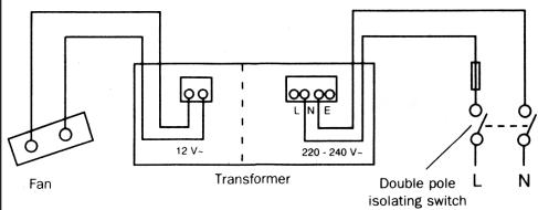
Transformer
- Wall mounted out of reach of bath or shower.
- Provides safety insulated supply for 12V a.c. fan.
What the installer will need
A double pole isolating switch with a minimum contact gap of 3mm (Wall or Ceiling mounted).
If metal switch boxes are used, earthing regulations must be followed.
Suitably rated 2-core cable (wiring from transformer to fan).
Guidelines for maximum cable run between the transformer and fan.
a) Limited to 0.3 volts drop. corresponding to 1.5% reduction in fan performance.
| Flexible | Fixed | |||
| Conductor size mm2 | 0.75 | 1.00 | 1.50 | 2.50 |
| Recommended max cable run-metres. | 4.50 | 6.00 | 9.00 | 15.00 |
b) Limited to 0.5 volts drop, corresponding to 3% reduction in fan performance.
| Flexible | Fixed | |||
| Conductor size mm2 | 0.75 | 1.00 | 1.50 | 2.50 |
| Recommended max. cable run-metres. | 7.50 | 10.00 | 15.00 | 25.00 |
- Suitably rated 2 core cable (supply to transformer) LV100, LV100PC, LV100H, LV100HP, LV100PIR.
- Suitably rated 3 core cable (supply to transformer LV100T only.
- 3mm Electricians Screwdriver and No.1 or 2 Pozidriv screwdrivers.
- To prevent a possible hazardous situation from water ingress, a condensation trap (Xpelair No. XCT100) must be fitted as close as possible to the fan in all situations where any section of the ductwork is positioned higher than the fan itself.
If wall mounting the fan, you will also need
- Masonry drill, Hammer & Chisel (or Core Drill equipment if available).
- Mortar to make good the hole if required.
If window mounting the fan
- You will need a window pane between 3mm and 6mm thick (preferably 4mm).
- Do not install in glass 3mm thick if the window pane area is more than 0.2 sq.m.
- If installing in sealed double glazing, a specially manufactured unit should be obtained from the glazing manufacturer. You will also require a special kit, Xpelair Cat. ref. DXDG.
- If installing in sash windows, you should mount the fan in the upper window. Secure the upper sash in the closed position and fit stops just below the level of the fan, to prevent damaging it when the sash is raised.
If installing in a panel which is between 9mm and 46mm thick, you will need a special kit, Xpelair Cat. ref. DXDG. Do not install these fans in panel which is more than 46mm thick.
If ceiling mounting the fan
Use the appropriate ancillaries for termination.
These items are available from Xpelair.
- WT10 - Termination ducting kit.
- CFWG100 - Soffit board termination grille (white or grey).
- FD100/3 and FD100/6 - flexible ducting.
Where to locate it
Fan
- Locate it as high as possible.
- At least 110mm from the edges of the mounting surface to the centre of the hole.
- As far away as possible from and opposite to the main source of air replacement to ensure airflow across the room (e.g. opposite the internal doorway).
- Near the source of steam or odours.
- Not where ambient temperatures are likely to exceed 50^ .
- If installed in a kitchen fans must not be mounted immediately above a cooker hob, or eye level grill.
- If installing in a room containing a fuel burning device which has a non-balanced flue, it is the installers responsibility to ensure that there is enough replacement air to prevent fumes being drawn down the flue when the fan is operating up to maximum extract. Refer to Building Regulations for specific requirements.
- Exhaust air must not be discharged into a flue used for exhausting of fumes from appliances supplied with energy other than electric. Requirements of all authorities concerned must be observed for exhaust air discharge and intake flow rates.
- When intended for use in possible chemical corrosive atmospheres, consult our Technical Service Department. (For overseas markets contact your local Xpelair distributor).
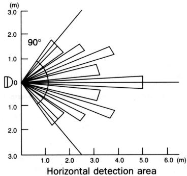
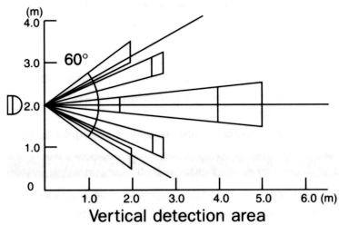
LV100PIR Only - Siting must ensure detection of movement. Care should be taken to avoid any obstructions that may affect detection beams A
Transformer
- In a loft or any convenient position on a wall (not suitable for ceiling mounting). The transformer must not be covered by loft insulation.
- Must be positioned the correct way up to fulfil ingress protection requirements.
- Not within 0.6m of a bath or shower cubicle, up to a height of 2.25m .
- Not where ambient temperatures are likely to exceed 50^ .
Installing the isolating switch and cables
-
Check that the electrical rating shown inside the back plate matches your mains supply.
-
Check there are no buried pipes or cables e.g. electricity, gas, water behind the switch location (in the wall or above the ceiling). If in doubt, seek professional advice.
- Isolate the mains supply.
- Lay in the cable from the supply to the double pole isolating switch.
- Lay in the cable from the isolating switch to the transformer location.
- Lay in the cable from the transformer to the fan location.
- Install the isolating switch.
- Make all connections within the isolating switch.
Note: On/off switch must be so situated that it cannot be touched by persons making use of the bath or shower.
WARNING: DO NOT MAKE ANY CONNECTIONS TO THE ELECTRICAL SUPPLY AT THIS STAGE.
Preparing the hole for the fan
If working above Ground Floor level, appropriate safety precautions must be observed.
WARNING: EYE PROTECTION MUST BE WORN DURING ALL DRILLING AND CHISSELLING OPERATIONS.
If installing in a wall
-
Check there are no buried pipes or cables in the wall or obstructions on the outside e.g. Electricity, Gas, Water. If in doubt, seek professional advice.
-
Mark on the wall the centre of the duct hole.
-
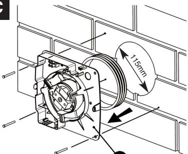
Use this centre to mark a circle to suit the wall duct (115mm diameter)
If core drill equipment is available
4a.Use as directed by Core Drill manufacturer.
If core drill equipment is not available
4b. Drill a centre hole right through the wall.
- Cut the hole. Do not cut right through the wall, cut from both sides. (The recommended method is to drill a series of holes, close together, around the edge of the cutting line and remove the brick between the holes with a chisel).
- Go outside and cut a hole in the outer wall, repeating the process described above.
- Cut ducting to the correct length if required. The wall tube supplied is telescopic and can extend to 300mm maximum.
- Fit the ducting. Ensure that the duct slopes down away from the fan to allow drainage of any incoming rain water to the outside.
- Make good the hole. Allows the Mortar to set before continuing the fan installation.
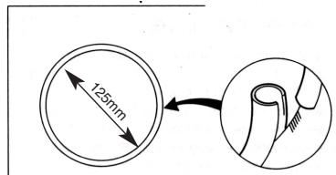
If installing in a window or panel
Cut a hole, 125mm in diameter. The centre of the hole should be at least 110mm away from the edge of the panel or pane of glass. It is recommended that you obtain a ready cut pane for window installation.
Xpelair
Toilet/Bathroom
Fans IV100,
IV100PC, IV100T,
IV100H, IV100HP & IV100PIR
installation &
operating
instructions
Please leave this leaflet with the fan for the benefit of the user
If installing in a ventilation sbaft
- Check there are no buried pipes or cables in the ventilation shaft. If in doubt, seek professional advice.
- Cut a hole 110mm in diameter, in the side of the shaft.
- If the shaft has cavity walls, use the wall tube to bridge the cavity.
- Fit ducting and condensation trap if necessary, positioning condensation trap as near to the fan as possible.
If installing in a ceiling
1 Check there are no buried pipes or cables in the ceiling joists etc. If in doubt, seek professional advice.
2 Cut a hole 115mm diameter.
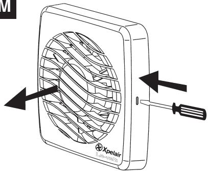
Preparing the fan for installation
Remove the front cover by pressing the release catches located on the sides of the unit with a 3mm screwdriver, whilst pulling the front cover forward M
Mount the fan in the hole
If working above Ground Floor Level, appropriate safety precautions must be observed.
If installing in a wall, ceiling or vent
Mark the position of the back plate B
- Hold the back plate so that the terminal block faces you in the left hand corner, and the lip points towards the hole.
- Carefully insert the lip into the wall duct/ceiling or vent shaft.
- Adjust the position of the back plate until it is level.
- Mark on the wall/ceiling or vent shaft the positions of the three fixing holes in the back plate.
- Remove the back plate from the ducting.
- Drill screw holes in these positions if necessary, and fit wall plugs if necessary.
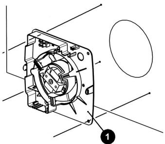
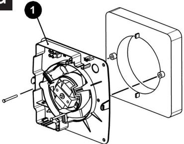
Mount the back plate
- Push the ribbed gasket (RG100) onto the lip of the back plate 1
- If installing in a ceiling or vent, push the larger diameter piece of the telescopic wall tube onto the ribbed gasket. Cut the tube to the required length, if necessary.
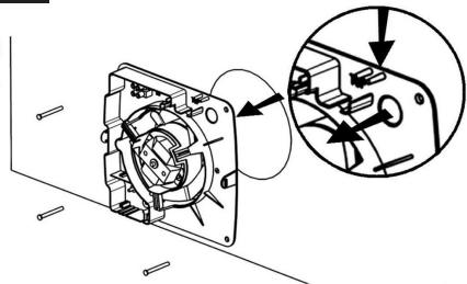
- If wiring the fan from behind, remove knockout. Feed the mains cable through the cable entry hole in the backplate to the terminals D
- If wiring from above, leave the cable free to be fitted into labyrinth.
- Insert the lip of the back plate into the wall duct/ceiling or vent shaft as before.
- Fasten the back plate to the wall/ceiling or vent shaft using appropriate fasteners. If using screws, do not overtighten the screws.
Mount the back draught shutter
- Peel the backing from the foam strip supplied and attach it around the outside of the lip on the back draught shutter.
- Go outside. Holding open the top and bottom vanes, insert the lip into the wall duct.
- Making sure the back draught shutter is level, mark the positions of the two fixing holes in the top right hand and bottom left hand corners.
- Remove the back draught shutters from the wall duct.
- Drill screw holes in these positions, and fit the remaining wall plugs.
- Holding open the top and bottom vanes, refit the back draught shutter and fasten it to the wall using the pointed end self-tapping screws. Do not overtighten screws.
- Make sure the vanes open and shut freely.
If installing in a window or panel
Sealing the hole E
If installing in a window or panel no more than 9mm thick, fit the white rubber gasket around the edge of the hole. If installing in a panel or sealed double glazing more than 9mm thick, a DXG Double Glazing kit is required. Follow the instructions supplied with the special kit.
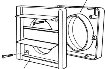
Attach the back draught shutter to the spacer F
- Holding open the top and bottom vanes, insert the back draught shutter ② into the spacer ③ so that the fixing holes in the top right and bottom left hand corners match those on the spacer.
- Insert two of the flat ended self-tapping screws provided and fasten the back draught shutter to the spacer.
Mount the fan in the window G
- Someone else must hold the back draught shutter and spacer in position outside, with the spacer against the glass.
- Make sure that the two raised fixing holes in the spacer are horizontal and are positioned within the hole.
- From inside, hold back plate so that the terminal block faces you in the top left hand and the lip points towards the hole.
- Align the holes in the back plate with those in the spacer.
- Insert two of the flat ended self-tapping screws provided in the fixing holes, and fasten the back plate to the spacer. Do not overtighten the screws.
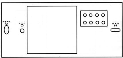
Mounting the transformer 1
The transformer can be fixed directly to the wall or attached to a suitable recessed wall box.
If fixing directly
- Remove two screws securing the cover, remove cover.
-
Position the transformer on the wall and mark the two fixing holes "A" and "C".
-
Drill and plug the two holes and fix the transformer with two pointed end self-tapping screws supplied.
If fitting to a recessed wall box
- Route the cables into the wall box and fix the wall box to the wall.
- Connect the protective earth conductor if required.
- Remove the two round knock-outs in the back of the transformer and route the 12v a.c. mains supply cables into their respective compartments.
- Fix the transformer to the wall by inserting the two screws provided through holes "A" and "C" and securing to the lugs on the wall box.
- For loft mounting, the transformer can be fixed to a wooded surface with the two screws.
- THE TRANSFORMER MUST NOT BE COVERED BY LOFT INSTALLATION.
Wire the fan H
MAKE SURE THE MAINS SUPPLY IS ISOLATED.
Wire the fan as shown in Feeding the cable between the two raised pegs, if wiring from above and through the labyrinth to the terminal block.
- For fixed wire and circuits the protective fuse for the appliance must not exceed 5A.
LV100T only
- To adjust the overrun timer insert a small screwdriver into the recess in the control spindle and turn clockwise to increase and anti-clockwise to decrease.
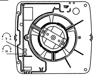
LV100H & LV100HP only K
- Humidity operation is factory set at approx 70% Relative Humidity (RH), but can be adjusted between 50% and 90% RH by control (H).
- Time delay is factory set at approx. 20 mins, but can be adjusted by control (T).
- Both controls are adjustable. Turn the controls clockwise to increase time or RH, and anti clockwise to decrease.
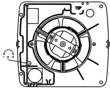
LV100PIR only
- Adjust the overrun period with control (T).
Turn screwdriver clockwise to increase and anti-clockwise to decrease.
All fans
- If wiring from above cut out the cable entry slot marked on top of the front cover.
- Fit the front cover by aligning it square to the duct and pushing it onto the duct until the release catches snap into the slots on the front cover.
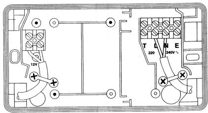
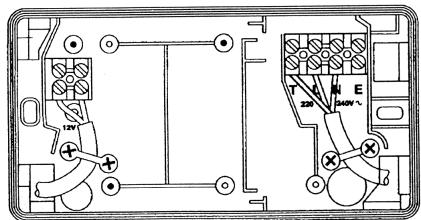
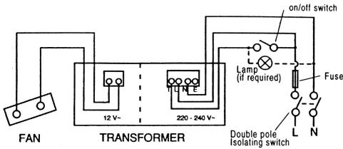
Wiring the transformer H & J
MAKE SURE THE MAINS SUPPLY IS ISOLATED.
-
If surface mounting, route 12V a.c. mains supply cable through the appropriate knockouts into their respective compartments.
-
Locate the cables in the cable grips (mains cable shown in H, and make the connections shown in J).
- Ensure all connections are tight.
- Switch off the mains electrical supply and remove fuses.
- Connect the cable from the isolating switch to the electrical supply wiring.
For fixed wiring circuits the protective fuse for the appliance must not exceed 5A. - Refit fuses and switch on supply.
Using your fan
LV100 only
- Operate the fan using on/off switch (not supplied). Repeat to switch off.
LV100PC only
- Operate the fan by pulling and releasing the integral pull cord.
- Repeat to switch off.
LV100T only
- Operate the fan using the on/off switch. When the switch is turned off, the fan continues to operate for the adjustable time delay period.
LV100H only
Fan operates when relative humidity exceeds the set level. When relative humidity drops the fan continues to operate for the adjustable time delay.
LV100HP only
- Manual mode: use the integral pull cord switch. When you switch off the fan, it goes into automatic mode after the time delay. (Light indicates when fan is operating in manual mode.
LV100PIR only
- The sensor detects movement in the room and activates the fan. When movement is sensed, the fan will run for a pre-set overrun period and any further movement sensed will re-start the sequence. This ensures that the room is only ventilated during and immediately after use. When the fan is first installed there will be a stabilising period of approximately five minutes. During this time the fan will run for up to two minutes.
Cleaning (recommended once a month)
A QUALIFIED ELECTRICIAN SHOULD CARRY OUT ALL CLEANING
- Before cleaning isolate the fan completely from the mains supply.
- Remove the front cover by pressing the release catches located on the sides of the unit with a 3mm screwdriver whilst pulling the front cover forward M
- To clean the front cover either wipe it with a damp, lint free cloth or wash it in warm soapy water. Thoroughly dry the front cover and re-fit.
- Do not immerse the fan in water or other liquids to clean any other parts of the fan.
- Never use strong solvents to clean the fan.
- Apart from cleaning, no other maintenance is required.
Móvo yia to LV100PIR L
Móvo yia to LV100PIR
aeggall ygalll lalw glc bally golly ll jil
aiee eae aee
M LsU
jai kai jai kai jai kai jai
y 1000
AaJbJbJbJbJbJbJbJb
aaii iiaii jlll llll aai
a. grrall 1jz jg s jz
aal aai ai gall aai al aiai
Lgaii jia jia jia jia jia jia jia jia jia jia jia jia jia jia jia jia jia jia jia jia jia jia jia jia jia jia jia jia jia jia jia jia jia jia jia jia jia jia jia jia jia jia jia jia jia jia jia jia jia jia j
yessssssssssssssss
juljuljlaaolduwly
aiiil a4sui jgaiiaai pae
HagalyduuJug
Jgaae aai
JSS 100000000000000000000000000000000000000000
JLJ 100000000000000000000000000000000000000000
aal
J 1
joo j
L
aill 100000000000000000000000
alj jaiiaolll J. Lajbui jayaiiaolll 5
aR H aaiiiaaiy jaiy jaiy i
aiee eae aee
1 baa j g a 1
alj gdisll.(T)cillllyg 1
Jalacclll Jlac aLg sall slal clll Jlac
.
(1) a Q ; 2
Jus 1s
Laiu 1.
a#y a#y
aill yaiil lalai jdi d
JgH Jd
Jgaoaay
a a a a a a a a a a a a a a a a a a a a a a a a a a a a a a a a a a a a a a a a a a a a a a a
1 1 1 1 1 1 1 1 1 1 1 1 1 1 1 1 1 1 1 1 1 1 1 1 1 1 1
ailllll jn aaiiie iie gii
a
glll lllll k j 1j 1j 1j 1j 1j 1j 1j 1j 1j 1j 1j 1j 1j 1j 1j 1j 1j 1j 1j 1j 1j 1j 1j 1j 1j 1j 1j 1j 1j 1j 1j 1j 1j 1j
aIyIyIyIyIyIyIy
24 1 1 1 1 1 1 1 1 1 1 1 1 1 1 1 1 1 1
ai a ai
B
s9 1e Saa yol sdiie Ia jy iie 1iie aill lal yol bll Jell k! ybl 9 1e Saa yol yol yol yol yol yol yol yol yol yol yol yol yol yol yol yol yol yol yol yol yol yol yol yol yol yol yol yol yol yol yol yol yol yol yol yol yol yol yol yol yol yol yol yol yol yol yol yol yol yol yel
F selall gld ydlal alld
1 1 1 1 1 1 1 1 1 1 1 1 1 1 1 1 1 1 1 1 1 1 1 1 1 1 1 1 1 1 1 1 1 1 1 1 1 1 1 1 1 1
1 1 1 1 1 1 1 1 1 1 1 1 1 1 1 1 1 1 1 1 1 1 1 1 1 1 1 1 1 1 1 1 1 1 1 1 1 1 1 1 1 1
G odaiall gde 2gysll
jlll llllllll 1 j 1 j 1 j 1 j 1 j 1 j 1 j 1 j 1 j 1 j 1 j 1 j 1 j 1 j 1 j 1 j 1 j 1 j 1 j 1 j 1 j 1 j 1 j 1 j 1 j 1 j 1 j 1 j 1 j 1 j 1 j 1 j 1 j 1 j
aaii iiaii aaii iiaii iiaii iiaii
glll klll jk lal lal 10 glll dlll 10 glll 10 glll 10 glll
alill oljy jolll jolll jolll jolll jolll jolll
Lgaiiie jssiuillnllall lannuall 0
sally clll Clll Clll Clll nnnnnae gall
aulllll
1
g 15e 15 15 15 15 15 15 15 15
ydsbokdall kcs
. 1 . 1 . 1 . 1 . 1 . 1 . 1 . 1 . 1 . 1 . 1 . 1 . 1 . 1 . 1 . 1 . 1 . 1 . 1 . 1 . 1 . 1 . 1 . 1 . 1 . 1 . 1 . 1 . 1 . 1 . 1 . 1 . 1 . 1 .
a aagaae 1
.
1
y 11. y
paaa aal baiy jay yj ybila aylll aai jla
s
15.21
aennnnnne
gai gai jai 1
... 1
a a a a a a a a a a a a a a a a a a a a a a a a a a a a a a a a a a a a a a a a a a a
i 1
/bilalglieaiaaiiiaaiy
0
y
C a#
aie (1-aj) aalal lalal
1
gill a jll a gai i gai
g 1 g 1 g 1 g 1 g 1 g 1 g 1 g 1 g 1 g 1 g 1 g 1 g 1 g 1 g 1 g 1 g 1 g 1 g 1 g 1 g 1 g 1 g 1 g 1 g 1 g 1 g 1 g 1 g
1 1
ailll llll llllll llll
D
Jlll jjI jie Jg 1000000000000000000000000000000000000000000
aill
a aal /aiall
Ls
aill aai /aiall /aiall aai all aai 1
aalall 1y jy
.3a1b11 j000000000000
Jzll lii ylll llll Jlll Jll
1
Jusall JSc. yll Jyall C lioo no JSLI Lg
i 1
J_2 all Li S,S,V
Jell lao Jssgall Jac
jLg 1y/1JzIJIJIJIJIJIJIJIJIJIJIJIJIJIJIJIJIJIJIJIJIJIJIJIJIJIJIJIJIJIJIJIJIJIJIJIJIJIJIJIJIJIJIJIJIJIJIJIJIJIJIJIJIJIJIJIJIJIJIJIJIJIJIJIJIJIJIJIJIJIJIJIJIJIJIJIJIJIJIJIJIJIJIJIJIJIJIJIJIJIJIJIJIJIJIJIJIJIJIJIJIJ
oossusnnnssssssssssssssssssssssssssssssssssssssssssssssssssssssssssssssssssss
gai
aai aiallal
.
aegnnnnae
y
aaiiaaii
yall jllj 1jll jll jll jll V
gssssssssssssssssssssssssssssssssss
= r1 r2·s r_n
4444444444444444444444444444
jlll jall cfo yydy yyyd y
JbI bll 9
aJzJ 1
C_6^3 = 128 × 12
gai alal gialo cale laa 190 lajiae aie bai
silllglc
S_ OBC = S_ COD + S_ BDO - S_ BOC
a jll jll lalall alal
Jouuui Juaa Juaa Juaa Juaa Juaa
- ( x,y) = ( ab,532) . 若 a = 1 b = 2 .
()
()
1 1
#
a
:Joo Joo Jc Jg aagall jj
jll k jll chw lsl no jy1 yle po 11. se yle
aill b
Jyj Jya Jaaal aay jao Jao Jao
aIlaal aIgai Iy
(1)
j 1
aJgdujzjj Jaalal jgiil slal jie
aagaae 0. glaer
caaa 154
gall lill gssu w s
4.2g3j1j1j1j1j1j1j1j1j1j1j1j
jz jz jz jz jz jz jz jz jz jz jz
A. a.b.c.d.e
Jzoll
jill wio j) bila 1e wuio jol
(2015 glc)
dsjgJzJgZallabzjps
aIulaljzdy. 1glll aaiiiaaiy
Jol
aaiy jaiy jaiy jaiy jaiy jaiy
p0. jc Jai 1
gjzjzjj jssyj
aagaaoo
aalg jjai C
joo aalll aagll gla aalll aayyssll 8 jno Sii
aalall
jia 2a gdo aLg gi cuiu gao no sii
| r,0. | 1,0. | 1,.. | .,V0 | rpoJusagall |
| 10,.. | 9,.. | 7,.. | ε,0. | JLILJbJcJdJfJg |
/1JUaLo 0. 1e J2yJ 1Jus (
| r,0. | 1,0. | 1,.. | ..,Vo | rpoJUaGall |
| oY,.. | oY,.. | 1,.. | ..,Vo | JLILJLbSaa |
| JLILJLbSaa |
J! · J! (Jall Jssj) wuuu uuuuauu J S J! .wJU WJUWJU WJU WJU WJU WJU WJU
1...JU! (Jzall Jz) wio 1y juiu
.
J 1 1 1 1 1 1 1 1 1 1 1 1 1 1 1 1 1 1 1 1 1 1 1 1 1 1 1 1 1 1 1 1 1 1 1 1 1 1 1 1 1
y
()
iiistii
山)p 111 pR clss slll gI Cti#
aLusu 151. p T aLusu Ljai yLusu jie e 1
s 100000000000000000000000000000000000000000000000000000000000000
j j j j j j j j j j j j j j j j j j j j j j j j j j j j j j j j j j j j j j j j j j j j j j j j j j j j j j j j j j j j j j j j j j j j j j j j j j j j j j j j j j j j j j j j j
c1iip 17p0a 14kssgjy jgs 1111 11 11 11 11 11 11 11 11 11 11 11 11 11 11 11 11 11 11 11 11 11 11 1
a 10000000000000000000000000000000000000000000000000000000000
aagabgblsaslaeabaaasie Jae aee aee aee aee aee aee aee aee aee aee aee aee aee aee aee aee aee aee aee aee aee aee aee aee aee aee aee aee aee aee aee aee aee aee aee aee aee aee aee aee aee aee aee aee aee aee aee aee aee
1 1
j jybl yjw l jg jlaow yll loj: jybl jao . (jy) yjy p jolkio uu ciao aliy iayi sie . (jydl gdl gai yjy rall jao laic Ldo. gial
1 1 1
aagall jaypawgll 2yjw wauu uol siall yjgl .
laill aegall jayw gall 2yjw wauu loaic.
.4y. g. jy
Jg2all
Notes
LV100, LV100PC,
LV100T, LV100H,
LV100HP,
LV100PIR

Do's and dont's
- Do read all the instruction leaflet before commencing installation.
- Do install each fan with a double pole isolating switch.
- Do make sure the mains supply is switched off before attempting to make electrical connections or carry out any maintenance or cleaning
- Don't install this fan in any window/panel which is less than 4mm thick.
Guarantee
Customers outside UK - see international below.
- UK: The fan is guaranteed against defects for 3 years from the date of purchase.
- Please keep your purchase receipt.
- If you have any problems, contact Xpelair's Head Office at the address shown below.
Technical advice and service
Customers outside UK - see international below.
UK: Xpelair have a comprehensive range of services including:
- Free technical advice help-desk from Engineers on all aspects of ventilation.
- Free design service, quotations and site surveys.
Service and maintenance contracts to suit all requirements.
Please ask for details:
- By telephone on Techline: +44 (0) 8709 000430
By fax on Techfax: +44 (0) 8709 000530 - At the address below
Head Office, UK Sales Office and Spares
Applied Energy Products Ltd, Morley Way, Peterborough, PE2 9JJ England
Telephone: +44 (0) 1733 456789
Fax: +44 (0) 1733 310606
Sales Hotline: +44 (0) 8709 000420
http://www.xpelair.co.uk
International
- Guarantee: Contact your local distributor or Xpelair direct for details.
- Technical Advice and Service: Contact your local Xpelair distributor.