
IMS 900 - Wireless conference system BEYERDYNAMIC - Free user manual and instructions
Find the device manual for free IMS 900 BEYERDYNAMIC in PDF.
| Brand | BEYERDYNAMIC |
| Model | IMS 900 |
| Category | Wireless conference system |
| Transmitter type | SE 900, UHF stereo transmitter |
| Receiver type | TE 900, UHF stereo diversity pocket receiver |
| Frequency range | 740-764 MHz, 774-798 MHz, 798-822 MHz, 842-866 MHz depending on version |
| Number of frequencies | 16 adjustable UHF frequencies per range |
| RF output power (transmitter) | Min. 10 mW, max. 100 mW (depending on regulations) |
| Signal-to-noise ratio | ≥ 90 dB (transmitter and receiver) |
| Receiver battery life | Approximately 10 hours with alkaline batteries |
| Transmitter power supply | DC 15-18 V adapter |
| Receiver power supply | 2 x 1.5 V AA batteries or NiMH rechargeable batteries |
| Transmitter dimensions | 210 x 204 x 44 mm |
| Transmitter weight | Approximately 1.1 kg |
| Receiver dimensions | 105 x 65 x 25.5 mm |
| Receiver weight | 105 g |
| Connectors (transmitter) | Combo XLR/6.35 mm inputs, 6.35 mm outputs, 6.35 mm headphone output, TNC antenna |
| Connectors (receiver) | Stereo headphone output 3.5 mm |
| Display | LC display (transmitter), numeric display (receiver) |
| Diversity function | True diversity with two antennas (receiver) |
| Operating modes | Switchable stereo and mono |
| Maintenance and cleaning | Clean with a soft dry or slightly damp cloth, without solvents. Clean battery contacts with denatured alcohol. |
| Safety | Avoid moisture, do not open the device, use only recommended accessories, protect your hearing by using the limiter. |
| Spare parts and repairability | Have any repairs carried out by an authorized technician under penalty of loss of warranty. |
Frequently Asked Questions - IMS 900 BEYERDYNAMIC
User questions about IMS 900 BEYERDYNAMIC
0 question about this device. Answer the ones you know or ask your own.
Ask a new question about this device
Download the instructions for your Wireless conference system in PDF format for free! Find your manual IMS 900 - BEYERDYNAMIC and take your electronic device back in hand. On this page are published all the documents necessary for the use of your device. IMS 900 by BEYERDYNAMIC.
USER MANUAL IMS 900 BEYERDYNAMIC
1.1 Features.. 26
1.2 Controls and Indicators.. 26
1.3 How to install the Transmitter 27
1.4 Setting up.. 27
1.4.1 How to connect the Antenna 27
1.4.2 How to connect the Antenna on the Front.. 28
1.4.3 Remote Antenna Connection 28
1.4.4 How to connect the Power Supply Unit.. 28
1.4.5 How to switch on the Transmitter 28
1.4.6 Line Level Input 28
1.4.7 Indication of Line Level 29
1.4.8 How to adjust Transmitter Frequencies 29
1.4.9 How to adjust Stereo or Mono.. 29
1.4.10 How to adjust Names.. 30
1.4.11 How to set the Lock Function.. 30
1.4.12 Input Sensitivity 30
1.5 Headphone for Monitoring.. 30
1.6 19"-Rack Mounting Page 31
- TE 900 Stereo Receiver Page 32
2.1 Features.. 32
2.2 Controls and Indicators 32
2.3 Setting up.. 33
2.3.1 Powering.. 33
2.3.2 How to replace the Batteries 33
2.3.3 How to connect the Earphone 34
2.3.4 How to switch on and adjust the Volume 34
2.3.5 How to select the Channel 35
2.3.6 Stereo/Mono Switch.. 36
2.3.7 Limiter Switch for Earphone.. 36
2.3.8 Squelch . 36
2.3.9 RF Signal Indication 36
2.3.10 RF Receiving Antennae . 37
2.3.11 Balance control.. 37
2.3.12 Belt Clip.. 37
- Earphone (optional). 38
3.1 Connection to mobile Devices.. 38
3.2 How to insert the Earphones 38
- General Instructions for a safe Operation.. 39
- Trouble Shooting.. 39
- Maintenance 39
- Licensing.. 40
- Components.. 40
- Accessories 40
- Technical Specifications.. 41
EC Declaration of Conformity 62
Operating Instructions IMS 900
Thank you for selecting the IMS 900 In-Ear System from beyerdynamic.
Please take some time to read carefully through this manual before setting up the equipment.
The wireless IMS 900 In-Ear System has been developed for stage and broadcasting applications. Furthermore, the system can be used for meetings and interpreting applications.
Safety Instructions Transmitter
- READ these instructions.
- KEEP these instructions.
- HEED all warnings and FOLLOW all instructions.
- When installing the unit make sure that the plugs can be accessed easily.
- Never expose the unit to water or excessive humidity. Do not install near swimming pools, spas, in a wet basement or in other excessively humid environments.
- Never put any objects filled with liquids (e.g. vases or drinking vessels) onto the unit. Liquids in units can cause a short circuit.
- For cleaning use a dry or slightly moistened cloth. Never use any solvent agents, as they damage the surface.
- Do not install or use this unit near sources of high heat, such as radiators, heat registers, flood lamps, spotlights, stoves, or other appliances.
- Always route cables running to the unit where they will not be pinched or cut by heavy or sharp objects.
- Always route cables so that nobody can trip over them and get hurt.
- Verify that the voltage rating of the unit matches that of the AC mains outlet you are to use. If you connect the unit to the wrong voltage, you may seriously damage it or suffer an electric shock.
- This unit needs a sufficient ventilation. Therefore, never cover the ventilation grilles. If sensible heat cannot escape, the unit can be damaged or inflammable material close to the unit can be ignited. Therefore, make sure the air can circulate freely through the ventilation grilles and keep inflammable material away.
- Never place burning objects (e.g. candles) onto the unit.
- If you use defective or inappropriate accessories, the unit can be damaged. Therefore, only use connecting cables specified by beyerdynamic. If you use cables tailored by yourself, the warranty will invalidate.
- If you move the unit to another place, make sure that it is secured to avoid injury from tip-over.
- Disconnect the unit from power during thunderstorms or when unused for a long period of time.
- If the unit has caused a defective fuse or short circuit, disconnect it from power and have it checked and repaired.
- Do not open the unit. You could suffer an electric shock. Refer all servicing to qualified service personnel.
- Do not touch the contact pins of the plug after unplugging the unit from power, you could suffer an electric shock.
- Never put any objects through the ventilation grilles or other openings. You could damage the unit and/or get hurt.
- Never use the unit when the power plug is damaged
Safety Instructions Receiver
- Protect the receiver from humidity, knocks and shock. You could damage the unit or you or others could suffer injuries.
- Before recharging or changing the battery switch off the device (receiver).
- Different brands of batteries may vary in length of up to 2 - 3mm . When you change the battery make sure there is a good contact.
- Clean the battery contacts from time to time with a soft cloth moistened with spirit or alcohol.
- If you do not use the device (receiver for several weeks or months, please remove the standard / rechargeable batteries as they can leak after some time and damage parts of the device (receiver). Even "leak proof" batteries are no warranty that they will not leak after some time. Failing to comply will invalidate the guarantee.
- Never dismantle standard /rechargeable batteries. The contained battery acid damages skin and clothes.
- Please do not throw used battery packs away with your household rubbish, but take them to your local collection points.
WARNING:
- The use of any In-Ear system and its associated earphones or headphones at elevated listening levels or for extended periods of time can result in permanent hearing damage. beyerdynamic cannot be held responsible for any damage of this type arising through the misuse of the IMS 900 system.
1. SE 900 Stereo Transmitter
The SE 900 is a UHF stereo transmitter. In each 24 MHz bandwidth there are 16 pre-programmed, selectable and non-interfering frequencies available. The SE 900 employs the latest high-efficiency transmitting circuitry and includes a rugged metal casing which combine to make it the right choice for audio professionals.
1.1 Features
LC-Display
9.5" casing
- Combo socket for balanced and unbalanced inputs
- For stereo and mono operation
UHF PLL Synthesized technology for 16 pre-programmed, selectable frequencies
- Dynamic expander to ensure a S/N ratio of greater than 90 dB
- A built-in limiter avoids distortion at high input levels
1/4" (6.35 mm) headphone connection
1.2 Controls and Indicators
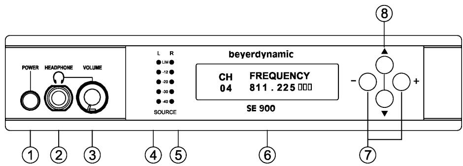
Front View
(1) Power switch On/Off
(2) Headphone connection
(3) Volume control for headphone/earphone
(4) Audio input (L) and limiter. Indicates audio signal strength on the left channel.
(5) Audio input (R) and limiter. Indicates audio signal strength on the right channel.
(6) LC-Display
(7) Setup buttons to adjust configuration
(8) Function buttons to select various menus
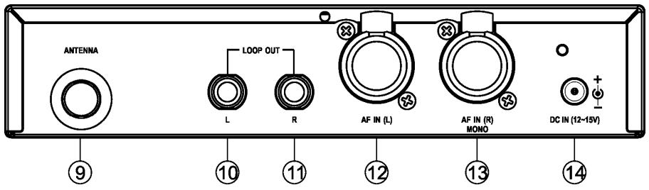
(9) Antenna connection (TNC)
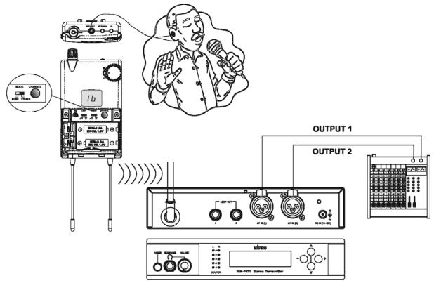
(10) Unbalanced audio output (left channel)
(11) Unbalanced audio output (right channel)
(12) Audio input (left channel). Combo socket for balanced and unbalanced signal inputs
(13) Audio input (right channel). Combo socket for balanced and unbalanced signal inputs
(14) DC connection for 15 VDC power supply unit
1.3 How to install the Transmitter
- Place the transmitter in the same room or area as the receiver.
- Always try to ensure a line of path between the transmitter and receiver; obstacles such as walls can significantly reduce the radio signal strength.
- Avoid using the IMS 900 system near digitally controlled devices, computers or mobile telephone equipment.
1.4 Setting up
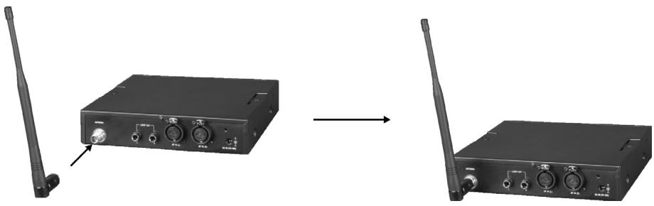
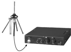
1.4.1 How to connect the Antenna
Connect the antenna to the antenna connection (9).
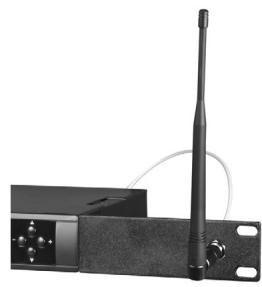
1.4.2 How to connect the Antenna on the Front
For connecting the antenna on the front of the receiver use the FBC 71 antenna mounting kit.
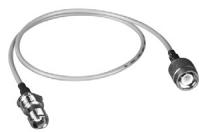
1.4.3 Remote Antenna Connection
For remote antenna connection use the AD-707A antenna with an MS 10 wall mounting accessory or microphone stand adapter and a 50 coaxial cable. The cable should not be longer than 5 metres.
AD 707A antenna with MS 10 wall mounting
Connection with coaxial cable
1.4.4 How to connect the Power Supply Unit
Connect the power supply unit (DC 12 V - 15 V/1 A) to the transmitter (14) and to the mains. The power cable can be fastened to the rear panel to prevent the plug from dislodging.
1.4.5 How to switch on the Transmitter
When the SE 900 transmitter is connected to the mains, switch on the power switch (1). The green LC-Display (6) will illuminate.
1.4.6 Line Level Input
A balanced or unbalanced line level input can be connected to the 3-pin XLR socket and an unbalanced line level input can be connected to the 6.35mm jack socket. This refers to the left and right channel.
1.4.7 Indication of Line Level
The strength of the line level for each channel input is displayed by LEDs (4) and (5) on the left hand side next to the LC-Display. In normal operation 3 LEDs are illuminated. With maximum level 4 should not be exceeded. If the input signal strength exceeds 4, the red warning LED will glow. The input signal level should be set properly to avoid signal distortion.
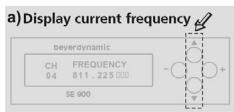
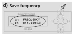
1.4.8 How to adjust Transmitter Frequencies
a) Press the up or down button until the LC-Display will show the preset frequency.
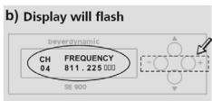
b) Press the right or left button. The LC-Display will start to flash.
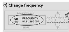
c) Press the right or left button to select the frequency.
d) Press the up or down button to store the selected frequency.
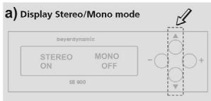
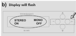
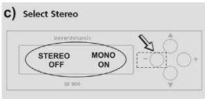
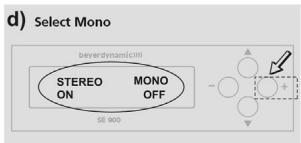
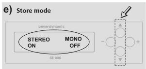
1.4.9 How to adjust Stereo or Mono
a) Press the up or down button until the LC-Display will show STEREO/MONO ON/OFF.
b) Press the right or left button. The LC-Display will start to flash.
c) Press the left button. STEREO is switched off.
d) Press the right button to switch off MONO and switch on STEREO.
e) Press the up or down button. The LC-Display will stop to flash and the setting is stored.
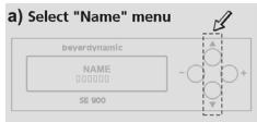
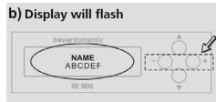
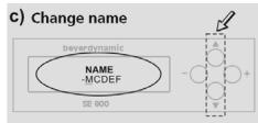
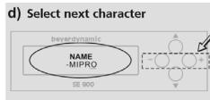
1.4.10 How to adjust Names
a) Press the up or down button until the LC-Display will show NAME.
b) Press the right or left button. The LC-Display will start to flash.
c) Press the up or down button to select letters or numbers.
d) Press the right or left button to jump to the next character. At maximum you can enter six letters/numbers.
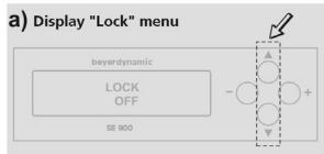
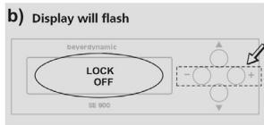
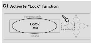
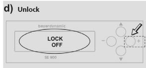
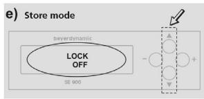
1.4.11 How to set the Lock Function
a) Press the up or down button until the LC-Display will show LOCK.
b) Press the left button. The display will show that the lock function is switched on: LOCK ON. All settings are now locked. No more settings can be made (except unlock) until the function is set to unlock.
c) To unlock press the right button until the display shows LOCK OFF. Further adjustments are now possible.
1.4.12 Input Sensitivity
a) Press the up or down button until the LC-Display will show INPUT SENSITIVITY.
b) Press the right or left button. The LC-Display will start to flash.
c) With the left button the input sensitivity is set to LOW, with the right button to HIGH.
d) Press the up or down button to store the setting.
1.5 Headphone for Monitoring
Connect a stereo headphone to the headphone socket (2). Adjust the desired headphone volume with the volume control (3). Make sure that the headphone is equipped with a stereo plug.
Important:
Adjust the headphone level to suit your needs and do not overdrive the headphone. The system will save and update the current setting automatically within 5 seconds after the last adjustment if no other button has been pressed in the meantime.
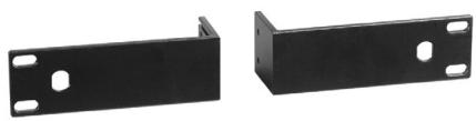
1.6 19"-Rack Mounting
One Transmitter
- To mount the transmitter into a 19"-rack mount a FB 71 mounting bracket on the left and right hand side of the transmitter.
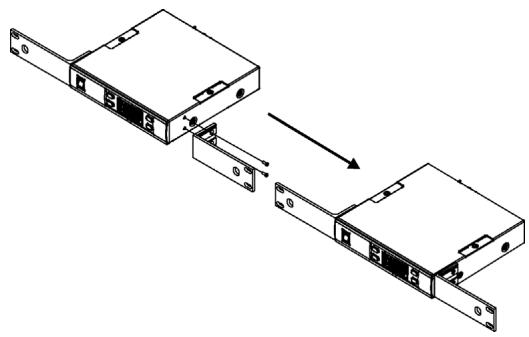
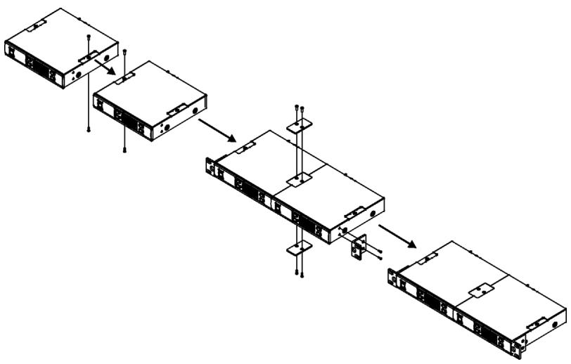
Two Transmitters
- Remove the screws on the top and bottom of the two transmitters.
- Mount the connecting plates on the top and bottom of the two transmitters.
- After joining the two transmitters together, mount a FB 72 mounting bracket on the left and right hand side.
2. TE 900 Stereo Receiver
The TE 900 is a UHF beltpack stereo receiver with 16 pre-programmed, selectable frequencies. To avoid dropouts and to improve the reception the TE 900 has been equipped with diversity technology. Further features are the switchable stereo/mono audio output and the lightweight, rugged casing.
2.1 Features
- Dual-antenna diversity reception to avoid dropouts and improve reception
Rugged casing - Numeric channel display and Auto-Power-Save function
- Switchable Stereo/Mono audio output
- PLL-synthesized technology with 16 pre-programmed, selectable frequencies
- LEDs for battery capacity and RF signal indication
Dynamic expander for S/N ratio >90 dB
Power supply via 2 batteries (1.5 V AA) - Unbreakable, flexible antennae
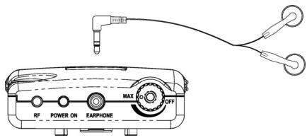
2.2 Controls and Indicators
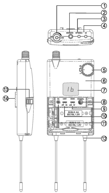
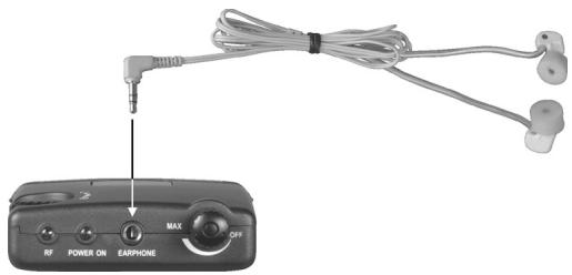
(1) On/Off switch and volume control for earphone
(2) Stereo mini jack for earphone
(3) Power indicator
(4) RF LED to indicate RF signal
(5) Balance control for right/left channel
(6) Casing
(7) Display to indicate the selected channel
(8) Channel selector button to select an interference-free channel
(9) Stereo/Mono switch to switch between Stereo or Mono audio output
(10) Limiter switch
(11) Squelch control to adjust the squelch level
(12) Antenna A and B. Fixed receiving antennae
(13) Battery cover. Battery compartment contains two AA-size batteries.
(14) Belt clip
2.3 Setting up
2.3.1 Powering
The TE 900 receiver is powered with 2 normal 1.5V batteries or rechargeable batteries of the AA-size. If you use conventional batteries, please use high-quality alkaline batteries. If you use rechargeable batteries, please use Ni-MH rechargeable batteries that are free from memory effect. If the TE 900 is powered with alkaline batteries, the operating time is approx. 10 hours. If the battery voltage drops below 2 volts, the power indicator (3) is illuminated red to indicate the decreasing capacity. If the battery voltage drops below 1.7 volts, the receiver is switched off automatically to avoid over-discharge or leakage.
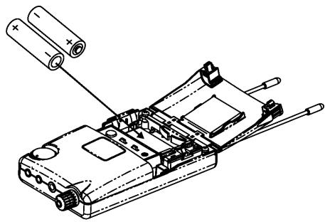
2.3.2 How to replace the Batteries
- Push down the two snap locks on the right and left hand side of the battery compartment and open it. Remove the batteries.
- Insert two new 1.5 volt batteries (AA) into the battery compartment observing polarity markings. Then close the battery compartment again.

Important:
- If you do not use the receiver for several weeks or months, please remove the batteries as they can leak after some time and damage parts of the receiver. Even "leak proof" batteries may leak after some time. Damage caused by leaking batteries is not covered under warranty.
- Clean the battery contacts from time to time.
- Please do not throw used battery packs away with your household rubbish, but take them to your local collection points.
- When using rechargeable batteries use conventional chargers.
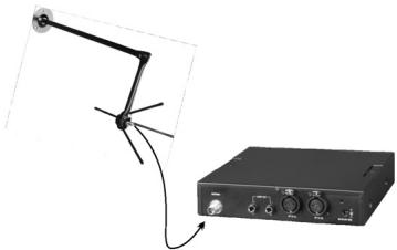
2.3.3 How to connect the Earphone
Connect the microphone to the mini stereo jack socket (2). You can use any conventional microphone or any other audio device.
Note:
Connect to the stereo jack socket (2) an earphone with stereo jack only. If you connect an earphone/headphone with mono jack, a short circuit can occur and damage the earphone/headphone.
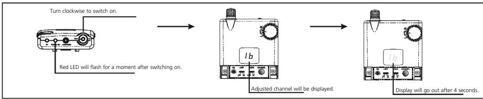
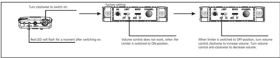
2.3.4 How to switch on and adjust the Volume
To switch on the receiver turn the on/off switch (1) on top of the receiver clockwise. As soon as the receiver is switched on, the power indicator (3) will illuminate and the display (7) indicates the current channel. The channel indicator (7) goes out after 4 seconds to save power. To increase the volume continue turning the on/off switch (1) clockwise. To decrease the volume turn the on/off switch (1) anti-clockwise. The volume can be limited with the limiter switch (10).
How to switch on the Limiter
Note:
When the battery capacity is insufficient, the system cannot be switched on. Please replace the batteries immediately or check if the batteries have been inserted correctly.
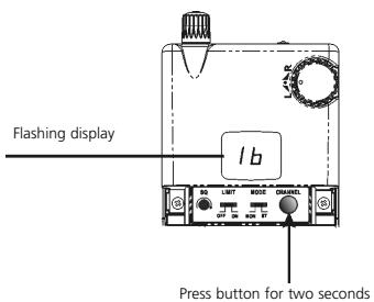
2.3.5 How to select the Channel
Hold down the channel selector button (8) for two seconds. The numeric display (7) will start to flash. Release the channel selector button. If you press the channel selector button (8) once again, the channel number will be increased. When channel 16 is reached, it will cycle back to channel 1. When you hold down the channel selector button for two seconds while the LED is flashing, the channel number will be increased automatically, until the button is released.

2.3.6 Stereo/Mono Switch
The stereo/mono switch (9) allows the use of earphones with either a stereo or mono output. The transmitter must be set at stereo transmission, if a stereo output is required.
Note:
In the stereo mode the receiver features a richer sound quality, but with a lower S/N ratio. In the mono mode the S/N ratio is higher as in the stereo mode. This is why some users feel that the mono mode has a longer receiving distance than stereo mode.
2.3.7 Limiter Switch for Earphone
As the volume can be extremely high, the user should switch the limiter (10) always to the "ON" position.
Note:
To protect your hearing, it is recommended to set the limiter always to the "ON" position. To avoid damage to your hearing you should remove the earphone after using it for a long period of time.
2.3.8 Squelch
The squelch control (11) can be adjusted with a small screwdriver. If you turn the squelch control clockwise, the effective reception distance is reduced, but also possible interferences. If you turn the squelch control anti-clockwise, the effective reception distance is increased, but also possible interferences. For optimum performance proper adjustment is required.
2.3.9 RF Signal Indication
When the RF LED (4) is illuminated, it is indicating that signals are received from the transmitter. When interference signals occur, however, this LED will illuminate as well. To eliminate interferences, you should select an interference-free channel.
2.3.10 RF Receiving Antennae
The TE 900 receiver operates with true diversity. Therefore, two receiving antennae (12) are needed. For optimum reception do not shorten or tangle the antennae. Make sure that there is no material near the antennae that is conductive or that might interfere with reception.
2.3.11 Balance Control
With the balance control (5) you can adjust the volume balance of the earphone between the left and right channel. When turned clockwise, the volume of the right channel remains unchanged, while the volume of the left channel decreases. When turning anti-clockwise, the volume of the left channel remains unchanged, while the volume of the right channel decreases. For an evenly balanced volume level between the left and right channels, the control should be set to the centre position.
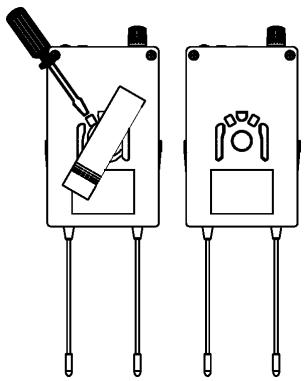
2.3.12 Belt Clip
The removable belt clip can be rotated 360^ . To remove the clip with a screwdriver rotate it 30^ to the right (clockwise).
3. Earphone (optional)
The earphones used for the TE 900 beltpack receiver can also be connected to other devices with a 3.5mm jack output such as CD players, MP3 players and laptops or PCs.
3.1 Connection to mobile Devices
- Connect the earphone to the 3.5mm jack output.
- Insert the earphones into your left and right ears.
- Slowly increase the volume to a comfortable listening level.
Warning:
Always turn the volume down before plugging the earphones into a sound source.
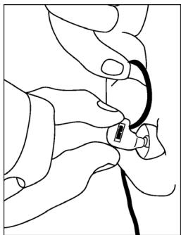
3.2 How to insert the Earphones
- Wrap the formfitting wire over the top and down the back of the ear.
- Insert the earphones into the left and right ears.
- Adjust the earphones to determine the most comfortable fit.
Note:
The right and left earphone are identified with different colour dots.
Red dot: Right ear
Blue dot: Left ear
4. General Instructions for a safe Operation
- Make sure that transmitter and receiver are on the same frequency.
- Check the receiver batteries and replace or recharge them if necessary. Use fresh alkaline batteries only.
5. Trouble Shooting
TE 900 Receiver
| Problem | Possible Cause | Solution |
| No function | ·Insufficient battery voltage ·Insufficient battery contact, battery inserted incorrectly | ·Replace or recharge the batteries ·Check the batteries and insert them again |
| No reception | ·Transmitter is not switched on ·Receiver works on a different frequency as the transmitter | ·Switch on the transmitter ·Make sure the transmitter and receiver are on the same frequency |
| No RF-indication | ·Distance between transmitter and receiver is too far | ·Reduce the distance between transmitter and receiver |
SE 900 Transmitter
| Problem | Possible Cause | Solution |
| No function | • Power supply is interrupted, unit is not connected to the mains and/or to the transmitter | • Connect the power supply unit to the mains and/or to the transmitter |
| Noise/chirping | • Two transmitters using the same frequency | • Change the frequency of one transmitter |
6. Maintenance
In the unlikely event of equipment failure, the product should be returned to your beyerdynamic dealer. Unauthorized attempts at repair may invalidate the warranty.
7. Licensing
In most countries around the world, wireless systems must be approved for use by the authorities and it may be necessary to obtain a licence to use it legally. Your local beyerdynamic dealer will be able to give you details on wireless system regulations for your area.
The components of the IMS 900 system are approved according to the directive
R&TTE 99/5/EEC:
TE 900
SE 900
under the CE 0336 ① identification.
8. Components
TE 900 UHF Stereo Diversity beltpack receiver for IMS 900, PLL- Synthesizer, Pilot tone, metal casing, Channel indication, 16 pre-programmed frequencies, Stereo/Mono Mode, integrated limiter, 850 - 874 MHz. Order # 480.312
TE 900 same as above, but 740 - 764 MHz . Order # 480.320
TE 900 same as above, but 774 - 798 MHz . Order # 480.363
TE 900 same as above, but 798 - 822 MHz . Order # 480.398
SE 900 Transmitter, 1/2 19"-metal casing, PLL-Synthesizer, 16 pre-programmed frequencies, Stereo/Mono Mode, LC-Display, integrated limiter, combined XLR/6.35 mm jack connections, 6.35 mm headphone connection, 850 - 874 MHz.. Order # 480.347
SE 900 same as above, but 740 - 764 MHz . Order # 480.355
SE 900 same as above, but 774 - 798 MHz . Order # 480.371
SE 900 same as above, but 798 - 822 MHz . Order # 480.339
9. Accessories
Supplied Accessories
SE 900 Transmitter
1 x Power supply unit
1 x Antenna
TE 900 Beltpack Receiver
1 x Earphone
2 × 1.5 ~V alkaline batteries, AA
10. Technical Specifications
SE 900 Transmitter
Modulation/oscillation FM stereo / PLL synthesizer
Frequencies 16 switchable, pre-programmed UHF
frequencies per frequency range
Frequency range. 740 - 764 MHz; 774 - 798 MHz; 798 - 882 MHz;
842-866MHz
RF output power. Min.: 10 mW (in Germany)
Max.: 100mW (50 load) depending on
the regulations in other countries
Frequency response 50 - 15,000 Hz
Stability ± 0.005%
Nominal deviation ± 40kHz
T.H.D. < 0.5%
Audio input. 2 x Combo socket, XLR / 6.35 mm jack
Audio output. 2 x 6.35 mm jack
Headphone output. 6.35 mm stereo jack with adjustable
volume; ≥ 16
Antenna output TNC
Power supply. DC adapter 15 - 18 V
Dimensions 210 x 206 x 44 mm
Weight. approx. 1.1 kg
TE 900 Receiver
Modulation/oscillation FM stereo / PLL synthesizer
Frequencies 16 switchable, pre-programmed UHF
frequencies per frequency range
Frequency range. 740 - 764 MHz; 774 - 798 MHz; 798 - 882 MHz;
842-866MHz
Stability ± 0.005%
Receiving sensitivity . .at 2 V input level,
S/N > 58 dB (mono audio)
Squelch adjustable 2 - 100 V
Signal-to-noise ratio 94 dBA
Stereo separation. 245 dB
Headphone output. 3.5 mm stereo jack
Impedance for earphone. 16
Power supply. 2 x 1.5 V batteries, AA
Current consumption approx. 130 mA
Operating time approx. 10 hours with alkaline batteries
EC-DECLARATION OF CONFORMITY
Application of Council directive:
1999/5/EEC R&TTE Directive
89/336/EEC, 93/68/EEC Electromagnetic Compatibility
73/23/EEC, 93/68 EEC Low Voltage Directive
Standards to which Conformity is Declared:
EMC EN 301 489-1/-9:2000
Radio Spectrum EN 300 422-1/-2:2000
Safety EN 60 065
Manufacturer's Name:
beyerdynamic GmbH & Co. KG
Manufacturer's Address:
Theresienstrasse 8, 74072 Heilbronn, Germany
Type of Equipment:
Wireless In Ear System IMS 900
Model Numbers:
SE 900 Transmitter, TE 900 Receiver
C0336
I, the undersigned, as an employee of beyerdynamic, hereby declare that the equipment specified conforms to the above Directive and Standards.
Manufacturer's Signature:
Uerid Rite
Date:
March 1, 2005
Full Name:
Ulrich Roth
Position:
Director of R&D
beyerdynamic))))
beyerdynamic GmbH & Co. KG
Theresienstr. 8
D-74072 Heilbronn
Tel. +49 (0)7131/617-0
Fax +49 (0)7131 / 617-224
E-mail: info@beyerdynamic.de
Farmingdale, NY 11735
Tel. +1 (631) 293-3200
Fax +1 (631) 293-3288
E-mail: salesUSA@beyerdynamic.com
Internet: www.beyerdynamic.com