TTPRO - Audio Interface FOCUSRITE - Free user manual and instructions
Find the device manual for free TTPRO FOCUSRITE in PDF.
User questions about TTPRO FOCUSRITE
0 question about this device. Answer the ones you know or ask your own.
Ask a new question about this device
Download the instructions for your Audio Interface in PDF format for free! Find your manual TTPRO - FOCUSRITE and take your electronic device back in hand. On this page are published all the documents necessary for the use of your device. TTPRO by FOCUSRITE.
USER MANUAL TTPRO FOCUSRITE
IMPORTANT SAFETY INSTRUCTIONS. 1
INTRODUCTION 2
GETTING TO KNOW THE UNIT 2
REAR PANEL CONNECTIONS 3
GETTING STARTED 3
FACILITIES AND CONTROLS 4
DISCRETECLASSAPRE-AMP 4
MID SCOOP EQ. 5
OPTICAL COMPRESSOR 6
OUTPUT LEVEL 6
LATENCY FREE MONITORING 7
MONITOR LEVELS. 7
LATENCY FREE MONITORING CONNECTIONS. 8
DIGITAL 8
DIGITAL CONNECTIONS 8
DIGITAL OUTPUT OPTION 9
MIC PRE-AMP INPUT IMPEDANCE 9
VARIABLE IMPEDANCE: IN DEPTH EXPLANATION. 9
IMPEDANCE SETTING QUICK GUIDE. 10
WORDCLOCK 10
WORKING WITH STEREO SIGNALS 10
A BEGINNER'S GUIDE TO COMPRESSION 12
FREQUENTLY ASKED QUESTIONS 14
TROUBLESHOOTING 16
CONTACTING US 16
IMPORTANT SAFETY INSTRUCTIONS
Please read all of these instructions and save them for future reference. Follow all warnings and instructions marked on the unit.
- Do not obstruct air vents in the rear panel. Do not insert objects through any apertures.
- Do not use a damaged or frayed power cord.
- Unplug the unit before cleaning. Clean with a damp cloth only. Do not spill liquid on the unit.
- Ensure adequate airflow around the unit to prevent overheating. As this is a Class A unit, we recommend leaving a blank 1U panel above the unit to aid ventilation.
- Unplug the unit and refer servicing to qualified service personnel under the following conditions: If the power cord or plug is damaged; if liquid has entered the unit; if the unit has been dropped or the case damaged; if the unit does not operate normally or exhibits a distinct change in performance. Adjust only those controls that are covered by the operating instructions.
- Do not defeat the safety purpose of the polarised or grounding-type plug. A polarised plug has two blades with one wider than the other. A grounding type plug has two blades and a third grounding prong. The wider blade or the third prong is provided for your safety. When the plug provided does not fit into your outlet, consult an electrician for replacement of the obsolete outlet.
WARNING: THIS UNIT MUST BE EARTHED BY THE POWER CORD. UNDER NO CIRCUMSTANCES SHOULD THE MAINS EARTH BE DISCONNECTED FROM THE MAINS LEAD.
This unit is supplied pre-configured to operate only at the voltage indicated on the rear panel. Ensure correct mains voltage is available and the correct fuse value is fitted before connecting to the mains supply. To avoid the risk of fire, replace the mains fuse only with the correct value fuse, as marked on the rear panel. The internal power supply unit contains no user serviceable parts. Refer all servicing to a qualified service engineer, through the appropriate Focusrite dealer.
RACK VENTILATION: AS THE TWINTRAK PRO IS A CLASS A DEVICE, PLEASE ENSURE IT IS PLACED TOWARDS THE BOTTOM OF YOUR EQUIPMENT RACK, WITH SUFFICIENT SPACE ABOVE AND BELOW FOR VENTILATION.
INTRODUCTION
TwinTrak Pro is an extremely focused and cost-effective stereo processor; the perfect 'analogue plug-in' for any modern audio recording studio. It provides all the necessary tools to:
- Track stereo or dual mono signals
- Process stereo or dual mono signals
Monitor signals within the mix via a simple hands-on control surface - Carry out essential processing for mixdown purposes
See TWINTRAK PRO AND YOUR STUDIO on page 17 for further information on how TwinTrak Pro can enhance your current studio setup.
TwinTrak Pro combines two facility-enhanced Class A pre-amps with a custom optical dual mono/stereo compressor. In addition, TwinTrak Pro boasts a number of unique features above and beyond its pre-amps and compressors, including variable input impedance, instant 'air', mid-scoop EQ and a latency free monitoring section that boasts enhanced routing and control options, featuring a DAC as standard, as well as an optional ADC.
When recording, do not assume you must route your signal through a mixing desk: simply connect your sources to TwinTrak Pro and connect the outputs of TwinTrak Pro directly into your sound card or recording device. This form of direct recording will ensure you record the cleanest signal at the highest quality, since it removes the possibility of noise being added to the signal when routing through a mixer.
Indeed, with many engineers now mixing within the DAW, and with TwinTrak Pro providing you with two comprehensive record channels and latency-free monitoring, you may no longer need your mixing desk, saving precious studio space.
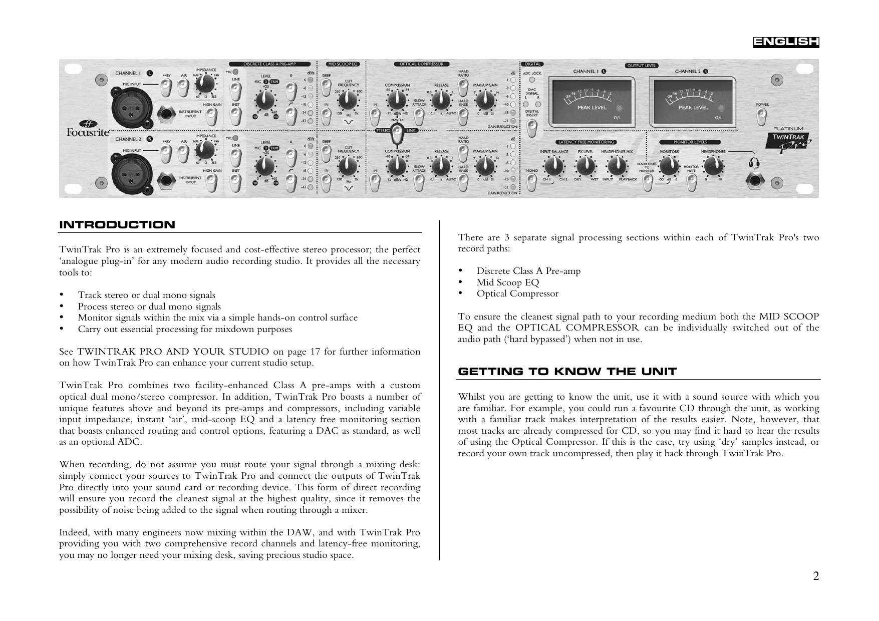
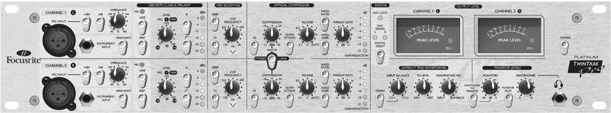
There are 3 separate signal processing sections within each of TwinTrak Pro's two record paths:
- Discrete Class A Pre-amp
Mid Scoop EQ
Optical Compressor
To ensure the cleanest signal path to your recording medium both the MID SCOOP EQ and the OPTICAL COMPRESSOR can be individually switched out of the audio path ('hard bypassed') when not in use.
GETTING TO KNOW THE UNIT
Whilst you are getting to know the unit, use it with a sound source with which you are familiar. For example, you could run a favourite CD through the unit, as working with a familiar track makes interpretation of the results easier. Note, however, that most tracks are already compressed for CD, so you may find it hard to hear the results of using the Optical Compressor. If this is the case, try using 'dry' samples instead, or record your own track uncompressed, then play it back through TwinTrak Pro.
REAR PANEL CONNECTIONS
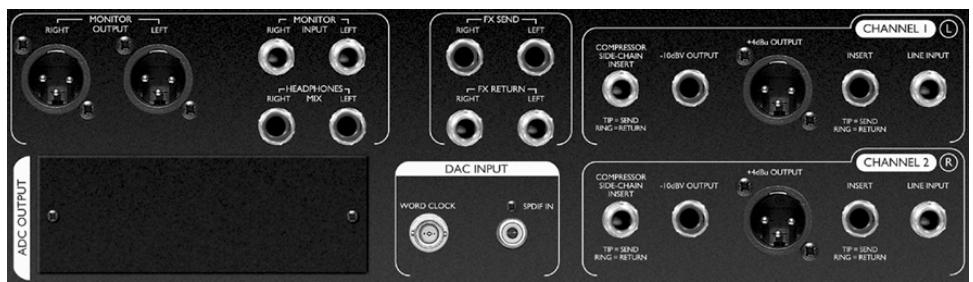
CHANNEL 1 (L) and CHANNEL 2 (R) - Each channel has a balanced (+4 dBu) TRS jack LINE INPUT connector on the rear panel, with balanced XLR MIC INPUT and unbalanced 1/4 ” jack INSTRUMENT INPUT connectors located on the front fascia. The TRS jack INSERT connectors on the rear panel allow an additional processor to be inserted into the signal chain between the pre-amps and the other processing sections of the unit. OUTPUTS are provided on both balanced (+4 dBu) XLR and unbalanced (-10 dBV) 1/4 ” jack connectors. There is also a TRS jack COMPRESSOR SIDE-CHAIN INSERT connector - see page 6 for details.
FX - The balanced (+4 dBu) TRS jack FX SEND and FX RETURN connectors allow effects units to be used in the monitor section without affecting what is being recorded. See LATENCY-FREE MONITORING and MONITOR LEVELS on page 7 for further details.
LATENCY-FREE MONITORING - The balanced (+4 dBu) TRS jack MONITOR INPUT connectors allow the output of a stereo mixer or sound card to be connected to the TwinTrak Pro's LATENCY-FREE MONITORING system. There are also balanced (+4 dBu) TRS jack HEADPHONES MIX connectors and balanced (+4 dBu) XLR MONITOR OUTPUT connectors, allowing the TwinTrak Pro to be connected to an external monitoring system. See LATENCY-FREE MONITORING CONNECTIONS on page 8 for further details.
DAC INPUT - The co-axial (RCA phono) S/PDIF connector allows a digital signal to be fed to either the monitoring section, or to the line input for further processing. This section also features a BNC wordclock out connector. See DIGITAL CONNECTIONS on page 9 for further details.
ADC OUTPUT - An optional ADC is available and can be retrofitted at any time. This provides an S/PDIF output as well as a BNC wordclock in connection. See DIGITAL OUTPUT OPTION on page 9 for further details.
GETTING STARTED
- Ensure that nothing other than the mains supply is connected to your TwinTrak Pro, then switch it on via the POWER switch on the right hand side of the unit. If your unit is permanently connected to a patchbay, ensure audio is not being fed to any connected speakers, thus avoiding any 'turn-on' speaker pops.
- Connect the appropriate OUTPUTS (either +4 dBu balanced XLR or -10 dBV unbalanced jack) from both channels on the rear panel of the TwinTrak Pro to your recorder or audio interface. If using the digital output option, connect the digital output to the digital input of your recorder or audio interface. See page 9 for more information on the TwinTrak Pro digital output option. If using your digital input, connect the digital input to the digital output of your recorder or audio interface.
- Connect the MONITOR inputs to your desk or sound card output and connect the MONITOR outputs to your monitor amplifier inputs or external powered monitor speakers.
- Ensure that each processing section is switched out (IN switch disengaged and unlit).
- Connect your input sources as required. Microphones can be plugged into the XLR MIC INPUTs on the front fascia. If you wish to connect a line-level source (to use the TwinTrak Pro's dynamics processing when mixing down, for example) connect this to the TRS LINE INPUTs on the rear panel. Alternatively, you may connect electric guitars or similar instruments to the INSTRUMENT INPUTs via the unbalanced 1/4 jack inputs on the front fascia. Be sure to select the right gain option (HIGH GAIN switched in for instruments that require extra gain, such as passive instruments) - see page 5 for more on the HIGH GAIN setting.
- Check that the correct input is selected in the DISCRETE CLASS A PRE-AMP section. If recording a line level source connected to the rear panel LINE INPUT, ensure the LINE switch is engaged. If recording an instrument through the front INSTRUMENT INPUT, ensure the INST switch is engaged. The MIC LED will illuminate if neither the INST or LINE switches are engaged. The MIC input is then automatically selected.
- Make sure the phase reverse () and HPF () switches are disengaged and that the LEVEL control is fully counter-clockwise.
-
If using a condenser or dynamic microphone that requires phantom power, engage the +48V switch. If you are unsure whether your microphone requires this phantom power, refer to its user guide. Phantom power can damage some microphones, especially ribbon microphones, so beware.
-
Increase the LEVEL control, checking the input level meter LEDs and ensuring the red O/L LED does not illuminate, except occasionally and briefly when the loudest signal is present. Note that the input is graded in dBfs, so a level of around 0dBu will only illuminate the first 2 LEDs.
See www.sospubs.co.uk/sos/may00/articles/digital.htm for more about dBu and dBfs.
- If using a microphone, ensure that the microphone placement is at its best. Before you start recording, alter the position of the microphone until you get as close as possible to the sound you want. Note that moving the microphone may have an effect on the level of the signal entering the TwinTrak Pro, requiring an alteration to the LEVEL setting.
- You can now eliminate any problematic mid frequencies by using the MID SCOOP EQ section. See page 5 for more information on the MID SCOOP EQ.
- The OPTICAL COMPRESSOR will help control the dynamics of the signal passing through the unit. See page 6 for more information on the OPTICAL COMPRESSOR.
FACILITIES AND CONTROLS
POWER (switch) - Turns the unit on. We recommend that the unit be powered up before connecting to any equipment that it is feeding, to avoid clicks or thumps which may harm output devices.
DISCRETE CLASS A PRE-AMP
This part of the unit is a pre-amplifier, used to amplify the incoming signal being fed to the MIC INPUT or INSTRUMENT INPUT to a suitable level before any further processing is applied.
MIC INPUT - This is an XLR connector that allows you to connect a microphone to the unit. If using the TwinTrak Pro's mic pre and feeding the output into a mixing console, bypass the console's own mic pre and connect the TwinTrak Pro output to the mixing console channel's line input. This will mean the superior TwinTrak Pro mic pre is used to process the signal, avoiding unwanted noise, distortion and colouration from an inferior mic pre. Always avoid routing the TwinTrak Pro's mic pre into a second mic pre, as this will produce greatly inferior results.
+48V (switch) - This provides +48V of phantom power for condenser microphones (affecting the MIC INPUT only). If you are unsure whether your
microphone requires phantom power, refer to its user guide before connecting, as it is possible to damage some microphones (most notably ribbon microphones) by providing them with phantom power.
AIR (switch) - This provides a pleasant boost in the high-end frequencies (affecting the MIC INPUT only). The exact boost frequency is dependent upon the microphone being used. This effect can simply be described as 'adding air' to the signal and enables the pre-amp to recreate the open and airy qualities of more expensive transformer-based pre-amps.
IMPEDANCE (knob) - Rotating the IMPEDANCE control alters the input impedance of the mic pre (affecting the MIC INPUT only). By adjusting the impedance of the TwinTrak Pro's discrete Class A transistor input, the performance of both the pre-amp and the microphone connected can be tailored to set the desired level and frequency response. For more information see the MIC PRE-AMP INPUT IMPEDANCE section on page 9.
INSTRUMENT INPUT - These are high impedance 1/4 jack inputs that allow you to connect an electric guitar or bass guitar to the unit without loading the pickups, and without the need for a DI box.
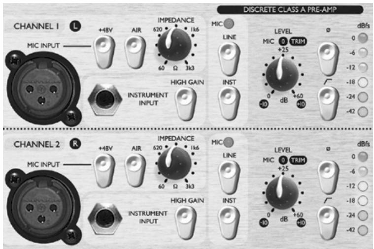
HIGH GAIN (switch) - This provides an extra 20 dBu of gain which is ideal when working with passive instruments. The LEVEL knob can then be used to adjust the gain level more accurately. To assess if HIGH GAIN is required, connect a sound source with the input LEVEL set to -10. Gradually increase the input level. If you are unable to get the level you require, even with the trim at +10, bring the LEVEL back to -10 and engage the HIGH GAIN switch. Now return to the LEVEL and adjust accordingly.
INSTRUMENT (switch), LINE (switch) and MIC (LED) - With TwinTrak Pro, you can select whether to record at mic, line or instrument level, all from the front fascia. If you wish to record via the INSTRUMENT INPUT, simply engage the INST switch. Once selected, it will illuminate. If you wish to record via the LINE INPUT, the INST switch must be disengaged, then simply engage the LINE switch. It too will illuminate when engaged. The MIC LED will illuminate if neither of the other input options are selected, and the MIC input will be selected automatically.
LEVEL (knob) - This is used to set the optimum input signal level. Connect an input signal to the unit, ensuring that the LEVEL control is set fully counterclockwise, and increase the LEVEL control whilst observing the LED signal meter. The red O/L (overload) LED may light occasionally, but only if the input signal gets particularly loud. If the O/L LED stays on continuously for any period, or you hear the unit distort during loud peaks, you should reduce the input LEVEL.
Note that the meter is calibrated to read 0 dBfs at the top of the meter - this has been set up to enable simple metering when recording to digital media. The best level to set for recording depends on your recording medium. If recording to an analogue medium like tape, where extra headroom is required, a level of -18 dBfs will give a suitable +4 dBu equivalent output. If recording to digital media, you may wish to record at a higher level, peaking at e.g. -4 to -6 dBfs. Confused? Visit www.sospubs.co.uk/sos/may00/articles/digital.htm for further illumination.
With the MIC INPUT selected, the LEVEL control provides 0 dB (fully counterclockwise) to +60 dB (fully clockwise) of gain. With the INSTRUMENT INPUT selected, the LEVEL control provides 0 dB to +20 dB of gain, with an additional 20 dB of gain available with the HIGH GAIN switch engaged, i.e. +20 dB to +40 dB. With the LINE INPUT selected, the gain is adjustable from -10 dB to +10 dB. Setting the LEVEL control to the 12 o'clock position will not alter the gain of a line level input signal.
(Phase Reverse switch) - This allows the phase of the input signal to be reversed. When recording a single source using more than one microphone, it is possible for the signals from the microphones to be out of phase, which affects the quality of the recording since signals that are out of phase tend to sound 'thin'. For
example, when recording a snare drum with two microphones (one on the top of the snare, the other on the bottom) they will be out of phase.
Use the phase reverse switch to reverse the phase on one of the microphones (but not both) - it normally doesn't matter which microphone you reverse. However, if the source is being picked up by another microphone (for example, by an ambient microphone) then you need to ensure that you do not put your two close microphones out of phase with the ambient microphone.
If you think two signals are out of phase, you can listen for phase as follows:
- On your monitoring system, pan one signal left and the other right.
- Set the monitoring to mono.
- Use the phase switch to reverse the phase on one of the signals. When the two signals are in phase, the signal sounds bigger.
(HPF switch) - This is a high-pass filter, which removes unwanted low frequencies such as stage rumble via microphone stands, or 'proximity effect' (where low frequencies are over-emphasised when using certain types of microphone at close range). The cut-off frequency is 75Hz with a slope of 18 dB per octave.
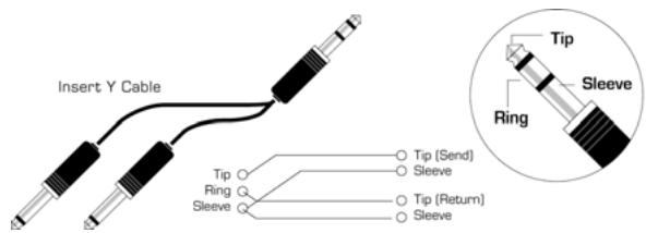
INSERT (rear panel connector) - The INSERT connector on the rear panel allows additional external signal processors to be inserted into the signal chain between the pre-amp and the other processing sections of TwinTrak Pro. This insert is a single TRS jack, configured as tip = send, ring = return. A specially configured lead (not provided) will allow you to connect this single point to both the input and output of an external signal processor, bringing the signal back to the point from which it was sent after the benefit of external processing.
MID SCOOP EQ
The MID SCOOP EQ section allows you to cut the selected frequency by up to 12 dB. This can be useful for removing troublesome frequencies when recording acoustic instruments and bass guitars.
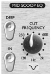
IN (switch) - Switches the MID SCOOP EQ into the signal path. When engaged, the red LED in the switch cap is lit.
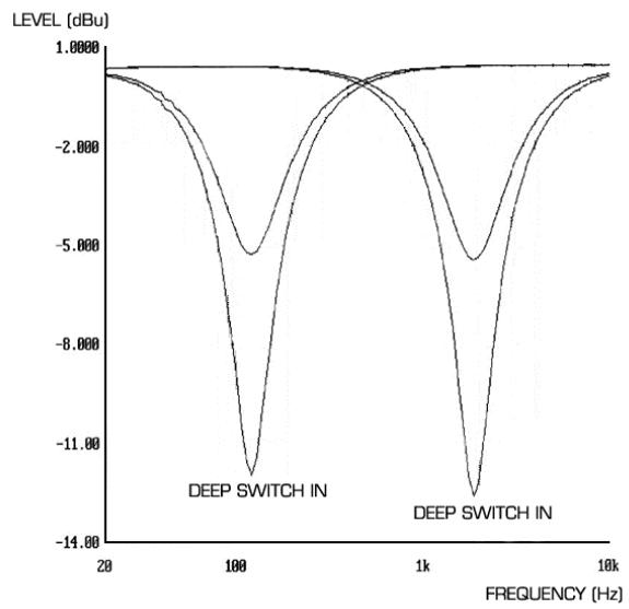
CUT FREQUENCY (knob) - Adjusting the CUT FREQUENCY knob allows the centre frequency to be 'tuned in'. The frequency range is 120Hz to 2kHz .
DEEP (switch) - When engaged (in), the DEEP switch increases the depth of cut from -6 dB to -12 dB.
OPTICAL COMPRESSOR
The OPTICAL COMPRESSOR acts like an automatic volume control, turning down the volume of a signal if it gets too loud. This reduces variation between loud and quiet passages, as it automatically reduces the gain when the signal exceeds a given volume, defined as the threshold. Using the OPTICAL COMPRESSOR helps to 'even out' a performance, stopping a signal from clipping and/or disappearing in the mix. See page 12 for a BEGINNER'S GUIDE TO COMPRESSION.
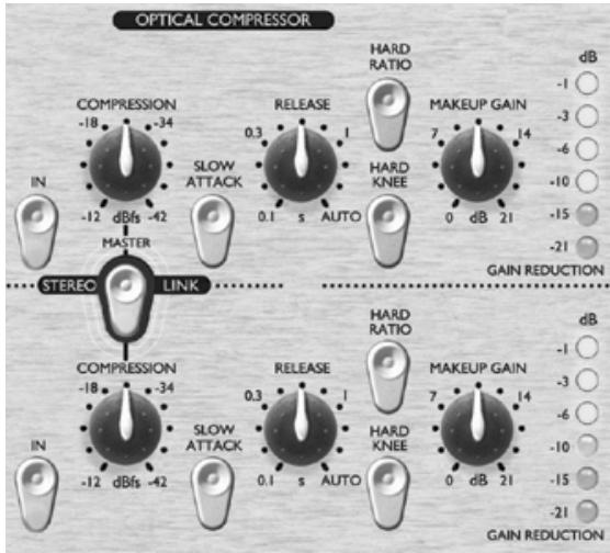
IN (switch) - Switches the OPTICAL COMPRESSOR into the signal path. When engaged, the red LED in the switch cap is lit.
COMPRESSION (knob) - Turning this knob clockwise increases the amount of compression by lowering the threshold. Turning the knob counter-clockwise decreases the amount of compression by increasing the threshold. Thus, this knob is essentially an inverted threshold control. Note that the signal is only compressed when it exceeds the threshold, so quieter passages maintain their natural dynamic range, whilst loud passages (that exceed the threshold) are compressed.
SLOW ATTACK (switch) - When engaged (in), selects a slower attack time, which allows more of the transient peaks of the signal through the compressor. This can help retain a sense of the original signal's dynamics when compressing heavily. For example, this can be useful to allow compression of a snare drum without losing the initial 'crack' of the drum stick striking the snare skin.
RELEASE (knob) - Determines the time taken for the gain reduction to return to normal once the signal drops below the threshold. The faster the release, the louder the signal appears to be.
HARD RATIO (switch) - When engaged (in), selects a higher compression ratio, which gives a very flat, compressed sound. Do not use the HARD RATIO switch if you want to maintain most of the original dynamics.
HARD KNEE (switch) - When engaged (in), selects a harder attack mode, which gives a very punchy and more obviously compressed sound.
MAKEUP GAIN (knob) - Sets the output volume of the compressed signal. Since compressing a signal makes it quieter, use the MAKEUP GAIN control to restore the signal to its original volume. Compare the volume of the original and the compressed signal by using the IN switch to switch the OPTICAL COMPRESSOR on and off.
GAIN REDUCTION (LED meter) - Displays the amount of gain 'lost' due to compression. Since compression reduces the volume of the signal, the meter drops as compression is applied: for example, a 10 dB drop shows as -10 on the meter.
COMPRESSOR SIDE-CHAIN INSERT (rear panel connector) - This is a TRS jack connector, configured in the same way as the main channel INSERT (tip = send, ring = return), which allows an external processor, such as EQ, to be inserted into the side-chain of the compressor. This allows frequency conscious compression techniques, such as de-essing, to be applied.
STEREO LINK (switch) - TwinTrak Pro can be stereo-linked, providing true stereo compression, allowing you to work with a stereo signal using just one set of controls. With STEREO LINK engaged (in), the top channel controls become master. When in stereo mode, gain reduction is only displayed on the master channel meter. See WORKING WITH STEREO SIGNALS on page 10 for further information.
OUTPUT LEVEL
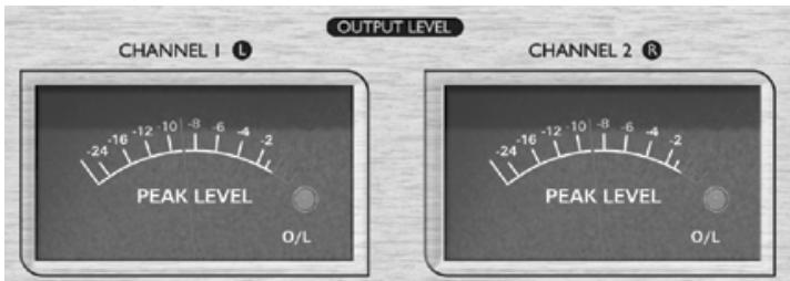
The inclusion of two custom peak-reading meters in the TwinTrak Pro's output section allows the user to accurately monitor the levels being sent to external analogue or digital equipment from the TwinTrak Pro's analogue and digital outputs. The peak-reading meter displays levels from -24dB s to 0dB s. An overload LED shows when levels are excessive - if this lights, reduce the level of signal being fed to the outputs using the controls in the MID SCOOP EQ and COMPRESSOR section (this assumes that your input LEVEL is already set correctly).
LATENCY FREE MONITORING
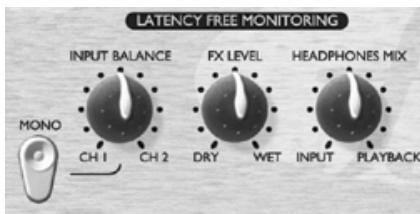
The LATENCY FREE MONITORING section is used in conjunction with the MONITOR LEVELS section to provide flexible monitoring of both the signal being recorded and an existing stereo mix.
Latency can be a major problem when recording to a computer-based digital audio workstation (DAW) via a sound card. If the signal being recorded has to pass through the DAW before being monitored, significant delays may occur as a result of the digital conversion and processing that takes place, making it difficult or impossible to sing, speak or play in time with any pre-recorded tracks being played back.
The TwinTrak Pro's LATENCY-FREE MONITORING section allows the user to monitor a mix of both the mono or stereo signal being recorded (fed directly from the unit before it passes through the digital recording system) and a stereo mix of pre-recorded tracks (acting as a mini mixer). Thus latency is eliminated and the recording artist can speak, sing or play along to the pre-recorded tracks in perfect time.
The controls in the LATENCY-FREE MONITORING section allow the engineer or artist to construct a headphone/external monitor mix as follows:
INPUT BALANCE (knob) - Allows you to adjust, within the monitor path, the stereo balance between the two input channels.
MONO (switch) - sums together the two monitor input channels, sending a mono signal to both left and right monitor outputs.
FX RETURN (knob) - Allows you to balance, within the monitor path, the amount of effected versus dry signal. The dry internal signals can be blended with the effected signal in the monitor mix by adjusting this knob, which runs from DRY (no effects) to WET (full effects).
This is a better than adding plug-in effects with the DAW for two reasons; firstly it eliminates any latency issues between input and playback signals, and secondly all the adjustments are localised conveniently on the front panel rather than being spread throughout the recording system. See FX SEND AND RETURN in the following section for further information on feeding FX units into the monitor path.
Note: The stereo FX SEND AND RETURN can also be used as a dual mono FX send and return, allowing you to feed different effect units to each channel. However, the FX return control is global, controlling the effects levels on both sides in equal proportions.
HEADPHONE MIX (knob) - Allows you to control the balance between the signals being tracked and the pre-recorded stereo mix fed to the monitor inputs from the DAW.
MONITOR LEVELS
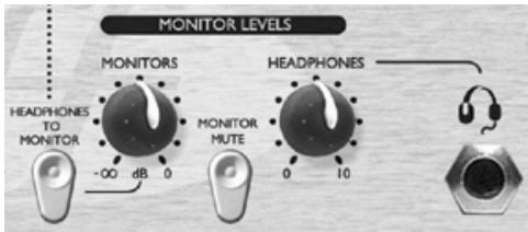
MONITORS (knob) - Allows independent control over the level being fed to external monitors.
HEADPHONES (knob) - Allows independent control of the overall level being fed to the headphones.
HEADPHONES TO MONITOR (switch) - Allows the headphone mix (as determined by the HEADPHONE MIX knob) to be sent to the external monitors via the monitor level knob. This means you can set up a headphone mix and switch it to your monitors whilst retaining independent control over the headphone mix level.
MONITOR MUTE (switch) - Mutes the output to the monitors (but not the headphones).
These controls allow the balancing between dry/wet and signal/monitor to be adjusted independently, making it quick and easy to set up. They also allow the artist to tweak his or her own headphone mix without affecting what the engineer is recording.
LATENCY FREE MONITORING CONNECTIONS
MOTOR INPUTS - These inputs are provided on balanced (+4 dBu) TRS jacks. They allow routing of your main stereo mix outputs (e.g. from DAW sound card output) to the TwinTrak Pro's LATENCY-FREE MONITORING section. This means that you can monitor both the stereo mix already recorded, AND the processed signals from your TwinTrak Pro at the same time. You can leave your TwinTrak Pro permanently rigged up in your recording system for tracking or reprocessing, whilst also allowing you to monitor the output from your main DAW.
MONITOR OUTPUTS - These outputs are provided on balanced (+4 dBu) XLR connectors. They allow routing of the signal connected to the MONITOR INPUTS (e.g. main stereo mix from DAW sound card output) to a pair of powered monitor speakers or monitor amplifier inputs. Note that these monitor outputs are separate from the headphone bus, and will relay only signal that is fed from the MONITOR INPUTS, unless the HEADPHONES TO MONITOR switch is engaged (see LATENCY FREE MONITORING section above).
HEADPHONES (front panel) - This output is a standard stereo TRS headphone jack, controlled by the HEADPHONES level knob beside it.
HEADPHONES MIX - These rear panel outputs are provided on balanced (+4 dBu) TRS jacks. They allow the headphones mix to be routed to an external amplifier, such as a headphone distribution amplifier. The signal is taken 'pre' the front-panel HEADPHONES level knob, thus retaining independent level control of headphones connected to the front panel HEADPHONES jack.
FX SEND AND RETURN - The rear panel has four balanced (+4 dBu) TRS jacks. The send is taken 'post' the balance and mono controls, and the return comes back in via the FX MIX control. This allows the two audio channels of the TwinTrak Pro to be routed to and from an external effects device such as a stereo reverb unit.
Adding FX at this point does not affect the dry signal that is being recorded, but allows reverb to be used to help an artist feel more comfortable when monitoring their own performance.
DIGITAL
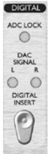
ADC LOCK (LED) - TwinTrak Pro features an ADC lock LED that illuminates when the optional ADC is synchronised to an external wordclock source. If an external wordclock source is connected, the ADC LOCK LED should light continuously. If it flickers it indicates bad jitter on the synchronising signal, requiring investigation of the wordclock-generating device.
DAC SIGNAL (LEDs) - TwinTrak Pro is the first Platinum unit to feature a DAC (Digital to Analogue Converter) as standard. This feature enables the user to feed stereo or dual mono digital signals into TwinTrak Pro, either for the purpose of monitoring, or to be re-processed through TwinTrak Pro's MID SCOOP EQ and OPTICAL COMPRESSOR sections. Two LEDs (left and right) show whether signal (either mono or stereo) is flowing through the DAC. These LEDs illuminate when the signal flowing through the DAC exceeds -12 dBfs.
DAC INSERT (switch) - When disengaged (out), the incoming digital signal is sent to the LATENCY FREE MONITORING section to act as the monitor input. When engaged (in), the incoming digital signal is processed through the TwinTrak Pro's input channels via the LINE input. N.B. the routing of the DAC signal to both the line input and monitor input is via the normalising of the LINE INPUT and MONITOR INPUT TRS jack connectors respectively - therefore it is imperative that these connectors are not occupied by jacks when using the DAC.
DIGITAL CONNECTIONS
DAC INPUT - The format for the digital input is S/PDIF and is on a single RCA phono (coaxial) connector. Wordclock output is also provided on a BNC connector. See page 10 for further information on wordclock.
DIGITAL OUTPUT OPTION
In addition to the analogue outputs, a high quality 24 bit, 128x over-sampled digital output may be fitted as an extra cost option, and can operate at sample frequencies of 44.1, 48, 88.2 or 96kHz . All of the following functions are available on the rear panel when this option is fitted:
S/PDIF OUTPUT - This 24 bit output is S/PDIF format on an RCA phono connector. If 16 bit resolution is required, the receiving device should dither the 24 bit signal to achieve 16 bit performance.
SAMPLE FREQUENCY (switch) - Two switches give a choice of four sample frequencies as marked on the rear panel. The left-hand switch selects between 44.1kHz (switch in) and 48kHz (switch out), and the right hand switch doubles the selected frequency, providing for 88.2 and 96kHz sample frequencies.
EXT WORDCLOCK INPUT - If an external wordclock source is fed to the BNC connector, the TwinTrak Pro will attempt to synchronise to it. When the unit is correctly locked to the external wordclock source the ADC LOCK LED will be illuminated (see above). See Wordclock on page 10 for more details.
Fitting the card
See the separate digital option owner's manual for instructions on how to fit the ADC.
MIC PRE-AMP INPUT IMPEDANCE
A major element of the sound of a mic pre is related to the interaction between the specific microphone being used and the type of mic pre-amp interface technology to which it is connected. The main areas in which this interaction has an effect are the level and frequency response of the microphone, as follows:
LEVEL - Professional microphones tend to have low output impedances and so more level can be achieved by selecting a higher impedance position.
FREQUENCY RESPONSE - Microphones with defined presence peaks and tailored frequency responses can be further enhanced by choosing lower impedance settings. Alternatively, choosing higher input impedance values will tend to emphasise the high frequency response of the microphone, allowing you to get improved ambient information and high end clarity, even from average-performance microphones. Various microphone/pre-amp impedance combinations can be tried to achieve the desired amount of colouration for the instrument or voice being recorded.
To understand how to use the impedance selection creatively it may be useful to read the following section on how the microphone output impedance and the mic pre-amp input impedance interact.
VARIABLE IMPEDANCE: IN DEPTH EXPLANATION
Dynamic moving coil and condenser microphones
Almost all professional dynamic and condenser microphones are designed to have a relatively low nominal output impedance of between 150 and 300 when measured at 1kHz . Microphones are designed to have such low output impedance because they are then less susceptible to noise pickup and they can drive long cables without high frequency roll-off due to cable capacitance.
The side-effect of having such low output impedance is that the mic pre-amp input impedance has a major effect on the output level of the microphone. Low pre-amp impedance loads down the microphone output voltage, and emphasises any frequency-related variation in microphone output impedance. Matching the mic pre-amp resistance to the microphone output impedance (e.g. making a pre-amp input impedance 200 to match a 200 microphone) still reduces the microphone output and signal to noise ratio by 6 dB, which is undesirable.
To minimise microphone loading, and to maximise signal to noise ratio, pre-amps have traditionally been designed to have an input impedance about ten times greater than the average microphone, around 1.2k to 2k . (The original ISA 110 pre-amp design followed this convention and has an input impedance of 1.4k at 1kHz .)
Input impedance settings greater than 2k tend to make the frequency-related variations of microphone output less significant than at low impedance settings. Therefore high input impedance settings yield a microphone performance that is more flat in the low and mid frequency areas and boosted in the high frequency area when compared to low impedance settings.
Ribbon microphones
The impedance of a ribbon microphone is worthy of special mention, as this type of microphone is affected enormously by pre-amp impedance. The ribbon impedance within this type of microphone is incredibly low, around 0.2 , and requires an output transformer to convert the extremely low voltage it can generate into a signal capable of being amplified by a pre-amp. The ribbon microphone output transformer requires a ratio of around 1:30 (primary: secondary) to increase the ribbon voltage to a useful level, and this transformer ratio also has the effect of increasing the output impedance of the mic to around 200 at 1kHz .
This transformer impedance, however, is very dependent upon frequency - it can almost double at some frequencies (known as the resonance point) and tends to roll off to very small values at low and high frequencies. Therefore, as with dynamic and condenser microphones, the mic pre-amp input impedance has a massive effect on the signal levels and frequency response of the ribbon microphone output transformer, and thus the 'sound quality' of the microphone. It is recommended that a mic pre-amp connected to a ribbon microphone should have an input impedance of at least 5 times the nominal microphone impedance.
IMPEDANCE SETTING QUICK GUIDE
In general the following selections will yield the following results:
High mic pre-amp impedance settings
- Will generate more overall level
- Will tend to make the low- and mid-frequency response of the microphone flatter
- Will improve the high-frequency response of the microphone.
Low pre-amp impedance settings
- Will reduce the microphone output level
- Will tend to emphasise the low- and mid-frequency presence peaks and resonant points of the microphone.
WORDCLOCK
Whenever multiple digital audio devices are connected together digitally, all the devices must be wordclock synchronised to avoid data transfer problems. All devices must send and receive their data at the same sample rate (e.g. 44.1kHz ) but they must also have their internal clocks running in sync. This ensures that all units send, receive and process their data streams simultaneously. Failure to achieve this will mean a drastic reduction in audio quality, and other unwanted audible artefacts, such as pops and clicks, may occur. At a sample rate of 44.1kHz for example, there are 44,100 spaces every second that need to have samples inserted. If there is a slight drift in one of the clocks, some of those samples will be 'missed'/will move forward one place, which results in distortion.
To avoid such problems, every digital system needs to employ wordclock. One unit should be designated the 'wordclock master', and all others should be designated 'wordclock slaves'. Setting this up is often simple, since most digital transfer formats include embedded wordclock data (e.g. S/PDIF, AES/EBU, ADAT). Where this is not the case (e.g. TDIF), wordclock can be provided via a separate wordclock connection. Note that timecode synchronisation (e.g. SMPTE) is different to
wordclock synchronisation, but equally important. Timecode enables recording and playback devices to run in sync with one another, and carries a regular series of absolute time values (hrs:mins:secs:frames). The two timing systems are quite independent.
Wordclock set-up when using ADC only
If no wordclock cable is connected, the TwinTrak Pro is the wordclock master, and the ADC transmits embedded wordclock via the S/PDIF connection. If a wordclock cable IS connected to the ADC, the ADC can be slaved to an external wordclock source.
Wordclock set-up when using DAC only
For standard use, no wordclock cable is required, since S/PDIF carries the embedded wordclock signal. If wordclock connection IS required (e.g. the user wishes to use a second low cost A/D converter which has only basic wordclock spec.) a wordclock cable can be connected to the DAC wordclock output to send wordclock signal to a second unit's wordclock input.
Wordclock set-up when using both ADC and DAC at the same time
Link the wordclock DAC output to the ADC's wordclock input using a short wordclock cable. The DAC wordclock output regenerates wordclock at the point of exit. So, you can run embedded-in-S/PDIF wordclock into the DAC, then send wordclock out of the DAC wordclock output, which is then received at the ADC wordclock input. You could also run the two separately, but this is the method we recommend as the noise performance is theoretically the best (everything runs from a single clock).
WORKING WITH STEREO SIGNALS
There are two basic techniques which can be used to record a sound source in stereo using two microphones. The first is to use a coincident pair of microphones. This technique uses a pair of identical directional microphones mounted as close to each other as possible (typically one above the other) at an angle of up to 90 degrees from one another, with each microphone feeding one channel. The microphones capture level differences between the left and right sides of the sound stage - because directional mics are used, the level varies in direct relation to the physical angle between the microphones and the sound sources.
The second technique is to use two identical omnidirectional microphones spaced a fixed distance apart. These microphones capture sounds from different positions in the sound stage at slightly differing times because of the physical distance between the two mics, and so they record what is known as 'time-of-arrival' information in the two channels.
For a complex sound source, such as an orchestra, it may be necessary for the engineer to use a combination of one of the above techniques with some 'spot' mics to bring distant sounds 'closer' in the recording.
Coincident microphones
The coincident pair technique is the most commonly-used stereo microphone technique used in radio, TV and commercial stereo recordings - due to the fact that this technique generally recreates the most faithful stereo image.
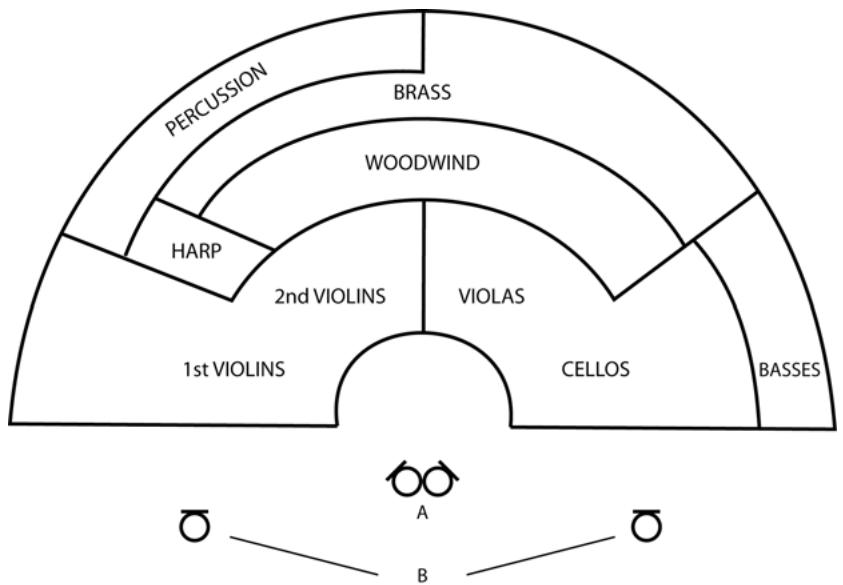
Coincident microphones do not record 'time-of-arrival' differences because the two microphones are mounted in such close proximity to one another that sound reaches both simultaneously. The diagram below shows how an orchestra might be recorded using this technique, where the microphones marked 'A' are in a coincident pair formation.
In this situation the two directional microphones are mounted on a stereo bar and face outwards so that the angle between them is 90 degrees. Using a stereo bar means that the mics aren't in exactly the same horizontal position, but they are close enough for any time-of-arrival differences to be inaudible. The microphone pointing to the left of the orchestra (at the first violins) would be panned hard left and the microphone pointing to the right (at the cellos) would be panned hard right.
The polar pattern of the directional microphones being used will affect the perspective of the recording, and therefore the positioning needs to be considered accordingly. In this example crossed cardioids would probably need to be placed above the conductor's head to pick up a full stereo image; a crossed figure-of-eight pair would have to be placed further back in order to cover the whole orchestra. As a result of this positioning, cardioids will pick up less of the room ambience and give a much 'closer' sound whilst the figure-of-eights would produce a more 'distant' sound and pick up more of the room ambience.
Spaced omnidirectional microphones
Omnidirectional mics cannot be used in coincident pairs because their directional response means they do not record level differences proportional to the angle of the incident sound. As a result, the only way to use two omnis is to space them apart and record the time-of-arrival differences. Spaced microphone techniques often do not create as accurate a stereo image as coincident techniques. This is mainly due to the fact that when these recordings are replayed, there is second set of time-of-arrival differences caused by the distance between the listener and the left and right loudspeakers. This often has the result that the stereo image becomes 'blurred', and can cause sounds to be perceived as grouped around the loudspeakers rather than spread uniformly between the speakers to create a full stereo image.
So, why might you choose to use a spaced microphone technique over a coincident pair? The main reason engineers choose this technique is so they can use high quality omni-directional microphones, whose low frequency performance is generally superior to that of directional microphones. It should also be noted that the quality of the stereo image captured by a carefully set up spaced omni technique is not a problem in many situations. The sound is still perceived as having width and the recordings often sound more spacious than those made using coincident techniques.
The microphones marked B in the diagram above are spaced omnidirectional mics. The mic to the left of the orchestra should be panned fully left and the mic on the right should be panned fully right. The distance they are set apart depends on the sound source being recorded but should generally be between a third and half the width of the sound stage. How far the microphones are placed from the orchestra would depend on the acoustics of the room and how much perspective was desired by the engineer.
There are no hard and fast rules as to which is the best microphone technique for stereo recording, and both techniques are capable of producing excellent results. Whichever technique you choose for a particular situation, experimentation and careful microphone placement are the keys to a successful stereo recording.
A BEGINNER'S GUIDE TO COMPRESSION
Compressors are probably the most widely used signal processors in the audio industry. A compressor can be thought of as an automatic volume control. Once the volume of the signal exceeds a certain level (called the 'threshold'), the compressor reduces the gain (in other words, 'turns the volume down'), causing the signal to be less loud than it would otherwise have been.
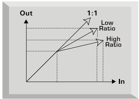
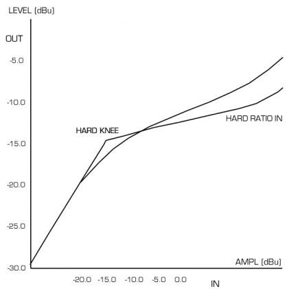
The amount by which the compressor reduces the gain is determined by the 'ratio'. The ratio is conventionally expressed as a numerical value, e.g. '4:1', which represents the amount by which the gain is reduced when the volume of the signal rises above the threshold.
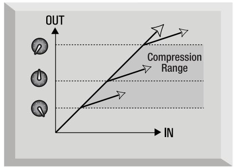
Let's take an example with some real numbers. If the threshold is set to -10 dB and the ratio is set to 4:1, any signal whose level exceeds -10 dB needs to rise in level by 4dB for the output of the compressor to rise by 1dB . Therefore an input signal with a peak at -6 dB (which is 4dB above the threshold) would emerge from the compressor with a peak at -9 dB (1 dB above the threshold). Signal levels below the threshold are unaffected, so if the signal in the above example varied between -20 dB and -6 dB before entering the compressor, it will vary between -20 and -9 dB after being compressed. Its dynamic range (the difference between the quietest and loudest parts of the signal in dB) is reduced from 14dB to 11dB .
Compression results in any variations in the volume of the signal (in other words, the signal's dynamic range) being reduced - the amount of this reduction is determined by the threshold (the level above which the gain is reduced) and the ratio (the amount by which the gain is reduced.) Higher ratios are referred to as hard ratios; lower ratios are called soft ratios.
Because compression causes a reduction in volume level of loud signals, gain must be applied after the compressor to bring the overall volume level back up, so that the maximum volume before the compressor is the same as that after the compressor. This is called 'make-up gain', and is necessary so that the maximum level of the signal is always the same, for correct level matching with any further processing or other equipment.
Once 'make-up gain' has been applied, the part of the signal that was lower than the threshold volume (and hence not compressed) will now be louder than it was before the compressor. This will cause any compressed instrument to sound louder. One use for this phenomenon is to give guitars more sustain.
In most pop music, the backing instruments (such as drums, bass guitars, rhythm guitars etc) tend to be compressed heavily (using a fairly hard ratio and low threshold), so that they remain at a consistent volume level throughout the track. This will provide a solid backing, without occasional drum hits or bass notes poking through (or disappearing from) the mix untidily.
A soft ratio tends to be used on instruments such as lead guitars or vocals that 'sit' on top of the mix. In this situation it is often desirable to preserve more of the dynamics of the original performance, to retain more expression. A reduction in variation of volume level is still required (for the reasons mentioned above), but not to the same extent.
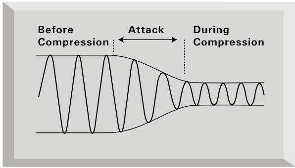
The other controls included on most compressors are attack and release.
Attack determines the speed at which the compressor starts to reduce the gain once the threshold has been exceeded. Think of it as the time taken to turn the volume down. Very short attack times mean the compressor 'kicks in' very quickly - short attack times are typically used for vocals in order to keep the levels under strict control. Longer attack times mean more of the original signal's attack dynamics are preserved - this is a good way of keeping percussive and guitar sounds exciting and punchy.
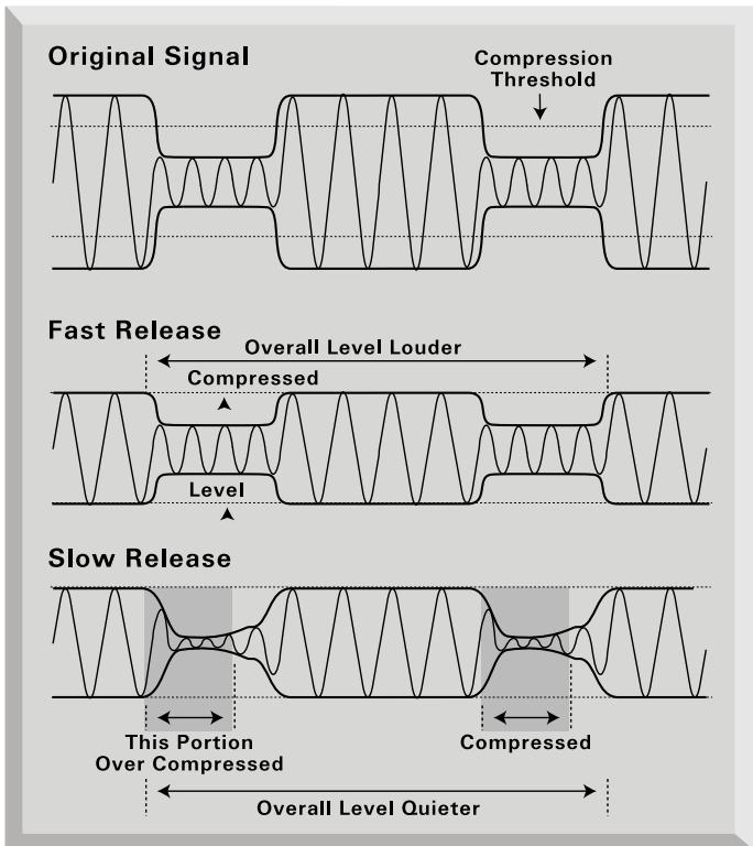
Release determines the speed at which the compressor stops acting once the signal drops below the threshold. Think of it as the time taken to turn the volume back up.
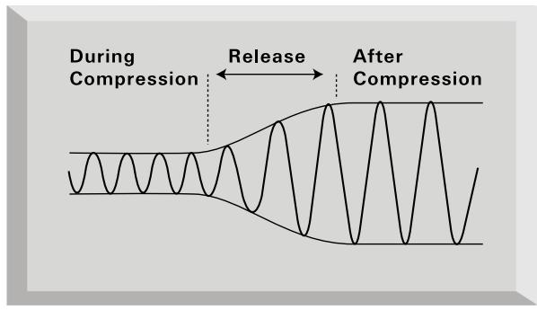
Short release times mean the compressor very quickly returns the signal to its normal level. This can produce a 'pumping' sound, where the changes in volume are very audible. Depending on the style of music, this can be undesirable, or a useful creative effect.
Longer release times may mean that parts of the signal below the threshold end up being compressed, or that the gain doesn't have a chance to return to normal before the next 'above threshold' sound - remember that the compressor works on the whole signal. See the diagram below:
FREQUENTLY ASKED QUESTIONS
Q. Who is the target customer for TwinTrak Pro?
A. TwinTrak Pro is ideally suited for the home recording enthusiast, especially anyone using a native DAW. Like other Platinum series products, TwinTrak Pro will find a home in professional environments such as recording studios, live sound installations, radio, TV, other broadcast, dubbing suites and post-production facilities.
Q. What kind of mic pres does the TwinTrak Pro use?
A. The TwinTrak Pro uses two of the same award-winning Class A mic pres as the VoiceMaster Pro.
Q. What is "variable impedance" and why is it a great feature?
A. Until the arrival of TwinTrak Pro, variable impedance was the kind of feature found exclusively on professional-level mic pres like the Focusrite ISA 428 Pre Pack. Variable impedance allows two things; the ability to match the mic pre's impedance closely to the impedance of the mic (all mics have different impedance) and also to allow the end user to "mix and match" different mic pre and mic impedances for greater tone coloration. See www.Focusrite.com for further detail.
Q. What does the AIR switch do?
A. The AIR control is a wire-wound inductor-based circuit, which closely emulates the characteristics of more costly transformer-based mic pres like Focusrite Red and ISA Series. While not exactly like a transformer-based pre, the air circuit does approximate the 'openness' of high frequencies characteristic of transformer-based pres. Now a whole new generation of customers can experience sound quality normally found only in professional recording studios.
Q. How does the MID SCOOP EQ work?
A. The boffins at Focusrite have identified the mid-range frequencies that are typically problematic when recording and processing vocals and instruments, and allowed the end user to "scoop" them out with a very simple and easy to use knob. Simply dial back what you don't like and you're done: remove the nasal 'goose-honk' tones from a problem vocal, or move an over-resonant 'DI'd instrument sound' closer to the ambience of a miked-up guitar or bass cabinet.
Q. The TwinTrak Pro has a high quality DAC built in as standard. Why is this an important feature and how would you use it?
A. This revolutionary feature can be used in two different ways. Firstly, the TwinTrak Pro's standard DAC allows the end user to feed a pair of digital outputs from a sound card or DAW (S/PDIF connector) into the latency free monitor circuit. So when recording a vocal or instrument you can monitor the pre-recorded material with the highest possible fidelity. And if you're running out of analogue outputs on your sound
card this feature means you can use a digital output instead, freeing up crucial analogue outputs for other purposes.
Secondly the DAC can be used in conjunction with the optional ADC to use the TwinTrak Pro as a 'hardware plug-in' for a DAW. A mix buss or single channel signal can be routed DAW/DAC/analogue compressor/ADC/DAW.
So TwinTrak Pro is not only a pair of integrated dual channel Class A mic pres plus EQ and dual mono/stereo compressor; it's also a latency-free monitoring device. Mic pres plus stereo monitoring plus digital connectivity means that the need for a standalone mixing desk is eliminated for most recording applications.
Q. How do I set up the TwinTrak Pro for these two different applications?
A. Engage the DIGITAL INSERT switch if you want to use the DAC to route your DAW's digital outputs into the TwinTrak Pro's compressor for 'hardware plug-in' processing. Leave this switch out if you want to use the DAC to route your DAW's digital outputs into the TwinTrak Pro's latency-free monitoring circuit.
Q. Does TwinTrak Pro have an optional ADC?
A. Yes, it uses the same acclaimed 24/96 option as TrakMaster, Penta and VoiceMaster Pro.
Q. Can I retrofit an ADC board to my TwinTrak Pro at a later date?
A. Yes, and you can do it yourself - it can easily be retro-fitted by the customer without any soldering etc, just a few screws to undo, and one clip-connector to join to the main PCB.
Q. Why is the 24 bit 96kHz specification important?
A. An A/D converter works by sampling the audio waveform at regular points in time, and then quantising those values into a binary number, which relates to the number of bits specified. The quantised signal must then be passed through a D/A converter before it becomes audible. In simple terms, the D/A essentially 'joins the dots' plotted by the A/D converter when the signal was first converted to digital. The number of dots to join, combined with how little those dots have been moved, determines how accurate the final signal will be compared to the original. The greater the sample rate and bit rate, the more accurate the whole digital process is. So 24 bit/96 kHz performance will ensure more accurate digital transfer of your audio information compared to 16 bit/44.1 kHz standards. This is especially important if further digital signal processing is to be applied to the signal once converted to digital, as any mathematical operations taking place on the data (for example as a result of a gain change, or dynamic effect process) may result in quantisation and rounding errors. The higher the resolution of the digital data, the smaller the audible effect of these errors.
Q. Does the TwinTrak Pro support wordclock?
A. Yes, via a BNC connector. See Wordclock on page 10 for more information on setting up wordclock connections on the TwinTrak Pro.
Q. What are the key compressor features?
A. The TwinTrak Pro's optical compressor is a Class A device and uses the same circuit design as the VoiceMaster Pro, but with the addition of hard- and soft-knee settings as well as a side-chain input. The compressors can operate independently ('dual mono') or as a linked true stereo pair.
Q. What is latency-free monitoring and who needs it?
A. Latency is the bane of every native DAW user's life. When tracking overdub vocals or a guitar track for example, an audible delay occurs. When recording, this delay is doubled (delay en route to hard disk + delay returning to monitoring circuit.) Focusrite's latency-free monitoring section eliminates latency by integrating the DAW monitoring into the circuit of TwinTrak Pro. The end result is tracking on a par with DAW systems featuring built-in DSP (and costing many thousands of dollars more).
Q. Is the TwinTrak Pro mic pre a Class A design? What does that mean?
A. Yes, it's the Class A award-winning mic pre used in the VoiceMaster Pro and all other Platinum range products. The TwinTrak Pro thus allows audio to be processed in a more linear fashion; put simply, the TwinTrak Pro's mic pre is able to reproduce all the detail of the input source without distortion or unwanted colouration.
Q. I heard that Class A devices generate a lot of heat. Is that something to worry about?
A. Absolutely not - all Class A devices do indeed run warm, it's a direct function of the way they enable audio to be passed transparently, and the TwinTrak Pro has been designed specifically to deal with this kind of situation. However, the usual Class A device rules apply, so it makes sense to put your TwinTrak Pro at the bottom of your rack, leave a 1U space above it, and leave the back of your rack mount case open when using the rack to ensure good ventilation.
Q. Does the TwinTrak Pro have an instrument input?
A. Yes, on the front panel, so you can connect a guitar, bass or other instrument directly to the unit with no need for a DI box.
Q. What are some of TwinTrak Pro's other monitoring capabilities?
A. A separate hardware processor (e.g. reverb) can be connected to the back of TwinTrak Pro. Much as one would experience in a pro studio, the performer could then have a "wet" reverberated signal in their headphones while tracking. The circuit allows mixing of wet vs dry signal, of the tracked signal vs pre-recorded material level, and overall output level.
Q. Is the TwinTrak Pro only suitable for recording vocals?
A. No, the TwinTrak Pro is suitable for recording many other sound sources too, such as electric guitars and bass (via its INSTRUMENT inputs). It is also ideal for applications such as recording the spoken word, live sound applications, radio and TV broadcast, dubbing, post production and can be used as a stereo buss compressor.
Q. What is the difference between +4 dBu and -10 dBV?
A. These are different signal operating levels. +4 dBu usually refers to professional equipment and -10 dBV usually refers to semi-professional or consumer equipment. It is important to make sure that any two or more devices connected to each other are operating at the same signal level. If the +4 dBu output of a device feeds the -10 dBV input of another device, this may cause the second device to overload. Alternatively, if the -10 dBV output of a device feeds the +4 dBu input of another device, the second device may receive a signal level which is too low (i.e. too quiet). -10 dBV devices are usually connected using a mono 1/4 jack. This is known as an 'unbalanced' connection. +4 dBu devices are usually connected using a TRS (stereo) 1/4 jack, or XLR. This is known as a 'balanced' connection.
Q. Should I use balanced connectors with my TwinTrak Pro?
A. Yes, where possible. The line level analogue input is balanced, operating at +4 dBu. The TwinTrak Pro provides both balanced (+4dBu) and unbalanced (-10dBV) output connectors. See the REAR PANEL CONNECTIONS section on page 3 for more information on connecting the analogue line level inputs and outputs.
Q. What is a 'side-chain'?
A. A side-chain is any signal that controls the action of the compressor. Usually the audio signal is split in two, with one part becoming the side-chain and controlling the compressor, and the other part of the audio signal being treated by the compressor. A side-chain insert allows much greater creative flexibility than if the audio signal alone is controlling the action. The most common way to use a side-chain is to EQ the part of the audio signal that is sent to the side-chain. Frequencies are either cut in order to stop the compressor reacting to particular frequencies, or boosted in order to make the compressor react more to particular frequencies. This is known as 'frequency-conscious compression'.
Q. How might I use the COMPRESSOR SIDE-CHAIN INSERT?
A. The main use of a side-chain insert is to use EQ to make the compressor react differently. For example, if you were putting drums through your TwinTrak Pro then you might find that the kick drum is causing the compressor to react the most, causing audible 'pumping' of the drums as the compression level rises after each kick drum and then is 'squashed' again. If this is undesirable, you could use the side-chain EQ to filter off some of the lower frequencies, reducing this effect. (Sometimes this effect is desirable, so you may wish to boost the low frequencies in order to emphasise this effect!)
Note: Both the main channel INSERT and the COMPRESSOR SIDE-CHAIN INSERT on the TwinTrak Pro require the use of a 'Y' cable. This is a cable that splits in two at one end. At the single end should be a stereo TRS jack and at the other end there should be two mono 'send' and 'return' jacks. Connections are shown below:
Q. Can I take my TwinTrak Pro with me when I travel internationally?
A. Yes, but the correct fuse and voltage setting must be used in each territory. There is a voltage selector on the rear panel of the TwinTrak Pro, which also houses the main fuse. If you are in the UK the voltage selector should be set to 230V and a 315mA fuse should be fitted. If you are in Europe the voltage selector should be set to 220V and a 315mA fuse should be fitted. If you are in North America the voltage selector should be set to 120V and a 630mA fuse should be fitted. If you are in Japan the voltage selector should be set to 100V and a 630mA fuse should be fitted. If you are in territory other than those mentioned, please look at the above settings and choose the setting and fuse value appropriate for the local mains voltage.
TROUBLESHOOTING
No LEDs illuminate
Is the POWER switched on?
- Is the correct mains voltage being used for your unit? If not, the fuse may blow, requiring the correct fuse to be refitted.
No output when using the MIC INPUT
Is the power switched on?
Is the LINE switch on the front panel switched out?
- Is the INST switch on the front panel switched out?
- Is the LEVEL set correctly? (See 'Facilities and Controls' on page 4)
- For microphones that require phantom power, is the +48V switch engaged? (If you are unsure whether your microphone requires phantom power, check the user guide for your microphone.)
No output when using the LINE INPUT
Is the power switched on?
- Is the LINE switch on the front panel switched in?
- Is the INST switch on the front panel switched out?
- Is the LEVEL set correctly? (See 'Facilities and Controls' on page 4)
No output when using the INSTRUMENT INPUT
Is the power switched on?
- Is the INST switch on the front panel switched in?
- Is the LEVEL set correctly? (See 'Facilities and Controls' on page 4)
The OPTICAL COMPRESSOR is not working
Is the compressor section's IN switch engaged?
- Is the LEVEL set correctly? If set too low, the signal level may not be high enough to activate the compressor.
- Is the COMPRESSION control set correctly? If set too low, the input level may not reach the threshold at which compression starts.
The OPTICAL COMPRESSOR is only working on the top channel
Is the lower channel compressor sections' IN switch engaged?
- Is the STEREO LINK switch engaged? If so, only the compression meter on the top channel displays the gain reduction and only the top channel controls have an effect on the compression settings. The top channel is called the master, as it controls both compressors when in stereo mode..
The MID SCOOP EQ is not working
Is the EQ section's IN switch engaged?
- Is the CUT FREQUENCY control set to a frequency that is present in the signal?
No wordclock lock
- Is your external wordclock source transmitting wordclock?
- Is the sample frequency set to match that of the wordclock-transmitting device?
- Is an external wordclock cable needed and, if so, is it connected?
No output from the digital output option
Is the sample frequency set correctly?
Is the receiving device set to receive at 24 bit?
Is the receiving device set to external sync?
CONTACTING US
If have any questions about your TwinTrak Pro, or are continuing to have difficulty, you can email us for help at tech@focusrite.com. Alternatively, telephone us on +44 (0)1494 462246 or contact your local distributor (see listing at the back of this manual).
INHALT
INHALT 17
DISCRETE CLASS A PRE-AMP
DYSFUNCTIONNEMENTS 48
POUR NOUS CONTACTER 48
TWINTRAK PRO AND YOUR STUDIO. 81
SPECIFICATIONS 89
FOCUSRITE DISTRIBUTOR LIST 91
CONSIGNES DE SECURITÉ
OPZIONE D'USCITA DIGITALE 57
IMPEDENZA D'INGRESSO DEL PREAMPLIFICATORE MICROFONICO.....57
IMPEDENZA VARIABILE: APPROFONDIMENTI 58
GUIDA RAPIDA PER L'IMPOSTAZIONE DELL'IMPEDENZA 58
WORDCLOCK 59
GUIDA ALLA COMPRESSIONE 59
FAQs. 61
OPZIONE D'USCITA DIGITALE
D. TwinTrak Pro supporta wordclock?
DISCRETE CLASS A PRE-AMP
- Gain range = 0 dB to 60 dB continuously variable
- Input impedance = 50 to 3K3 continuously variable
EIN = 128 dB measured at 60 dB of gain with 150 Ω terminating impedance and 20 Hz/22 kHz bandpass filter - THD at minimum gain (0 dB) = 0.0004% measured with +16 dBu input signal and with a 20 Hz/22 kHz bandpass filter
- THD at maximum gain (60 dB) = 0.003% measured with a -36 dBu input signal and with a 20 Hz/22 kHz bandpass filter
- THD at maximum input level (26.5 dBu) = 0.005% measured with a 20 Hz/22 kHz bandpass filter
Frequency response at minimum gain (0dB) = flat at 10Hz and -2dB down at 200kHz
Frequency response at maximum gain (60dB) = -2 dB down at 10Hz and 200kHz
CMRR at full gain (60dB) = 80 dB
LINE INPUT RESPONSE
- Gain range = -10 dB to +10 dB continuously variable
Input impedance = 10K from 10Hz to 200kHz - Noise at main output with gain set to 0dB = -94 dBu measured with a 20Hz / 22kHz bandpass filter
- Noise at -10dBV output with gain at 0dB = -100dBu measured with a 20Hz / 22kHz bandpass filter
- Signal to noise ratio relative to max headroom (27 dBu) = 121 dB
- Signal to noise ratio relative to 0dBfs(+22dBu) = 116 dB
- THD at unity gain (0 dB) = 0.0006% measured with 0 dBfs (+22 dBu) input signal and with a 20 Hz/22 kHz bandpass filter
Frequency response at unity gain (0dB) = 0.1 dB down at 10Hz and -3dB down at 200kHz
INSTRUMENT INPUT RESPONSE
- Gain range (High Gain switch out) = 0 dB to 20dB continuously variable
- Gain range (High Gain switch in) = 20 dB to 40dB continuously variable
Input Impedance = >1 Meg - Noise at minimum gain (0 dB) = -90 dBu measured with a 20 Hz/22 kHz bandpass filter
- Noise at maximum gain (40 dB) = -78 dBu measured with a 20 Hz/22 kHz bandpass filter
- THD at minimum gain (0 dB) = 0.006% measured with -10 dBu input signal and with a 20 Hz/22 kHz bandpass filter
Frequency response at unity gain (0dB) = 0.5 dB down at 10Hz and -1 dB down at 200kHz
Frequency response at maximum gain (40dB) = 6 dB down at 10Hz and -1dB down at 200kHz
INPUT METER
- 6 LED peak reading meter is calibrated relative to 0 dBfs where 0 dBfs = +22 dBu (the maximum level which can be correctly converted by the optional internal A/D converter before overload occurs). The meter calibration points are as follows: -
| Meter panel calibration value | Equivalent dBu value |
| 0 dBfs | +22 dBu (the maximum signal level the ADC can convert before digital distortion occurs) |
| -6 dBfs | +16 dBu |
| -12 dBfs | +10 dBu |
| -18 dBfs | +4 dBu (the normal signal level in an analogue system to allow headroom for additional processing such as EQ) |
| -24 dBfs | -2 dBu |
| -42 dBfs | -20 dBu |
CHANNEL INSERT
- Unbalanced input and output on balanced (TRS) socket as follows:-
- Tip = Send (Output)
- Ring = Return (Input)
- Signal level equivalent to -6dB below normal operating level.
HIGH PASS FILTER
Roll off = 12 dB per octave 2 pole filter
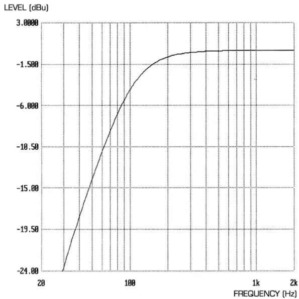
Frequency range:
Cut off frequency: -3 dB at 120 Hz
-6 dB at 85 Hz
-12 dB at 56 Hz
OPTICAL COMPRESSOR
- Threshold hold range = -12 dBfs (10 dBu) to -42 dBfs (-20 dBu).
- Compressor ratio (Hard Ratio switch out) = 2.5:1
- Compressor ratio (Hard Ratio switch in) = 6:1
Attack time (Slow Attack switch out) = 0.5 ms.
Attack time (Slow Attack switch in) = 5 ms. - Release time = 100 ms to 1 s and then auto release mode when the release knob is turned fully clockwise. Auto release creates a release time dependent upon the average level of the incoming signal.
- Noise = -94 dBu measured with a 20 Hz/22 kHz bandpass filter.
Makeup gain = 0 to +21dB
Ratio:
COMPRESSOR SIDECHAIN INSERT
- Can be used to input an independent signal to trigger compression or to allow the sidechain audio to be sent in and out of the unit via an external processor, such as an EQ for frequency conscious compression and de-ressing of vocals.
- Connector is an unbalanced input and output on balanced (TRS) socket as follows:-
- Tip = Send (Output)
- Ring = Return (Input)
- Signal level equivalent to -6 dB below normal operating level.
MID SCOOP EQ
EQ shape = Peak
- Centre frequency = Variable between 120 Hz and 2 kHz
Cut (Deep switch out) = -6 dB
Cut (Deep switch in) = -12 dB
Q (Deep switch out) = 1.5
Q (Deep switch in) = 3
FX SEND
- Unbalanced output, signal level equivalent to -6 dB below normal operating level.
- Noise = -94 dBu measured with a 20 Hz/22 kHz bandpass filter.
Maximum output signal level = +20 dBu
FX RETURN
Balanced input
- Operating level = +4 dBu
HEADPHONES MIX
-
Unbalanced output, signal level equivalent to -6 dB below normal operating level.
-
Noise = -94 dBu measured with a 20 Hz/22 kHz bandpass filter.
Maximum output signal level = +20 dBu
MONITOR INPUT
Balanced input
- Operating level = +4 dBu
MONITOR OUTPUT
Balanced output
- Operating level = +4 dBu
- Noise = -98 dBu measured with a 20 Hz/22 kHz bandpass filter and monitor level knob at maximum output level (fully clockwise).
Maximum output signal level = +26 dBu
DAC PERFORMANCE
- Playback sample frequency = 32 kHz to 192 kHz .
Maximum bit depth = 24 bit
Maximum analogue output level = +21 dBu. - Dynamic Range = 111 dB measured with A weighted filter.
- Wordclock BNC connector outputs a regenerated wordclock at the sample frequency contained within the SPDIF signal connected to the RCA connector.
OUTPUT METER
- Calibrated for 0dBfs = +22 dBu and indicates the level after the output fader being sent to both the internal AD converter and the TwinTrak Pro XLR output.
- O/L LED is lit when any section of the unit (including the headphone output) reaches a level greater than 0 dBfs (O/L: LED triggered at +22.4 dBu).
WEIGHT
5kg
DIMENSIONS
482 mm (W) x 88 mm (H) x 180 mm (D)
FOCUSRITE DISTRIBUTOR LIST
Australia
Electric Factory Pty Ltd
Phone: +61 3 9480 5988
Fax: +61 3 9484 6708
Email: elfa@ozmail.com.au
Austria
Klangfarbe GesmbH
Phone: +43 1 5451717-53
Fax: +43 1 5451717-9
Email: concepts@klangfarbe.com
Belgium
Audio XL Belgium
Phone: +32 11 23 23 55
Fax: +32 11 23 21 72
Email: info@eml.be
Brazil
Pride Music
Phone: +55 11 6975-2711
Fax: +55 11 6975-2772
Email: info@pridemusic.com.br
Bulgaria
Bulcomp Ltd
Phone: +35 92 943 59 10
Fax: +35 93 265 27 58
Email: info@bulcomp.com
Canada
c/o Digidesign (see USA)
Colombia
Proasseco LTDA.
Phone: 571 600 6907
Fax: 571 621 2250
Email: hpinzon@proaseco.com
Croatia, Slovenia, Bosnia, Macedonia and
Serbia
Music Export
Phone: +49 89 746 123 90
Fax: +49 89 746 123 92
Email: Music.Exports@t-online.de
Cyprus
Technosound
Phone: +357 2 499971
Fax: +357 2 499986
Email: technosd@cylink.com.cy
Czech Republic
Audiopolis Studio Systems
Phone: +420 2 4148 3501
Fax: +420 2 4148 3505
Email: sales@audiopolis.cz
Mediaport
Phone: +420 27173 5610
Fax: +420 2 7273 4897
Email: info@mediaport.cz
Denmark
New Musik AG
Phone: +45 86 190899
Fax: +45 86 193199
Email: aaudio@intouch.com
Finland
Studiotec Ky
Phone: +358 9 5123 5330
Fax: +358 9 5123 5355
Email: sales@studiotec.fi
France
Audiopole
Phone: +33 1 45 14 47 80
Fax: +33 1 45 14 47 90
Email: commercial@audiopole.fr
Germany
Digital Media Technology
Phone: +852 2721 0343
Fax: +852 2366 6883
Email: dmthk@dmtpro.com
Hungary
Absolute
Phone: +361 252 0196
Fax: +361 341 0272
Grisby Music Professional
Phone: +39 0 71 7108471
Fax: +39 0 71 7108477
Email: grisbymusic@tin.it
Japan
All Access Inc.
Phone: +81 52 443 5537
Fax: +81 52 443 7738
Email: info@allaccess.co.jp
R. O. Maldives
Island Acoustics
Phone: +960 32 0032
Fax: +960 31 8624
Email: islmusic@dhivehinet.net.mv
Mexico
Email: ventaspa@varinter.com.mx
Netherlands
Total Sonic BV
Phone: +31 23 554 6001
Fax: +31 23 554 6061
Email: info@totalsonic.nl
New Zealand
Protel
Phone: +64 4 801 9494
Fax: +64 4 384 2112
Email: rob@wm.protel.co.nz
Norway
Lydrommet
Phone: +47 22 80 94 50
Fax: +47 22 80 94 60
Russia, Baltics, Ukraine
AT Trade
Phone: +7 095 956 1105
Fax: +7 095 956 6882
Email: alpha-brand@attrade.ru
Singapore/Malaysia
Team 108
Phone: +65 748 9333
Fax: +65 747 7273
Email: 108@team108.com.sg
Slovakia
Centron
Phone: +421 264 780767
Fax: +421 264 780042
Email: centron@ba.profinet.sk
South Africa
Eltron Pty Ltd
Phone: +27 11 787 0355
Fax: +27 11 787 9627
Email: eltron@iafrica.com
South Korea
Best Logic Sound Co
Phone: +82 2 515 7385
Fax: +82 2 516 7385
Email: bscoltd@hitel.net
Spain
Media Sys S.L
Phone: +34 93 426 6500
Fax: +34 93 424 7337
Email: mediasys@interplanet.es
Sri Lanka
HiFi Centre Ltd
Phone: +94 1 580442
Fax: +94 1 503174
Email: hifi@eureka.lk
Sweden
Polysonic ab
Phone: +46 31 7069050
Fax: +46 31 7069110
Email: polysonic@polysonic.com
Switzerland
Bleuel Electronic ag
Phone: +41 1751 7550
Fax: +41 1 751 7500
Email: bleuel-elec@swissonline.ch
Taiwan
Digital Media Technology (Taiwan) Ltd
Phone: +886 2 25164318
Fax: +886 2 25159881
United Arab Emirates
NMK Electronics Ent.
Phone: +971 4626683
Fax: +971 626682
Email: nmk@emirates.net.ae
United Kingdom & Ireland
Focusrite Audio Engineering Ltd
Phone: +44 (0) 1494 462246
Fax: +44 (0) 1494 459920
Email: sales@focusrite.com
USA
Digidesign
Phone: +1 866 FOCUSRITE
Fax: +1 650 731 6399
Email: prodinfo@digidesign.com
Dino_Virella@digidesign.com
Venezuela
Avcom C.A.
Phone: +58 212 237 7762
Fax: +58 212 237 8275
Email: jmendez@avcom.com.ve
Vietnam
Vistar
Phone: +84 4 824 3058
Fax: +84 4 825 0099
Email: hanoimusic@netnam.org.vn
Other territories not listed:
Please contact Focusrite United Kingdom.