TX8P - Powered speaker YORKVILLE - Free user manual and instructions
Find the device manual for free TX8P YORKVILLE in PDF.
User questions about TX8P YORKVILLE
0 question about this device. Answer the ones you know or ask your own.
Ask a new question about this device
Download the instructions for your Powered speaker in PDF format for free! Find your manual TX8P - YORKVILLE and take your electronic device back in hand. On this page are published all the documents necessary for the use of your device. TX8P by YORKVILLE.
USER MANUAL TX8P YORKVILLE
This lightning flash with arrowhead symbol, within an equilateral triangle, is intended to alert the user to the presence of uninsulated "dangerous voltage" within the product's enclosure that may be of sufficient to constitute a risk of electric shock to persons.
The exclamation point within an equilateral triangle is intended to alert the user to the presence of important operating and maintenance (servicing) instructions in the literature accompanying the appliance.
Instructions pertaining to a risk of fire, electric shock, or injury to a person
CAUTION: TO REDUCE THE RISK OF ELECTRIC SHOCK, DO NOT REMOVE COVER (OR BACK).
NO USER SERVICEABLE PARTS INSIDE.
REFER SERVICING TO QUALIFIED SERVICE PERSONNEL.
Read Instructions: The Owner's Manual should be read and understood before operation of your unit. Please, save these instructions for future reference and heed all warnings.
Clean only with dry cloth.
Packaging: Keep the box and packaging materials, in case the unit needs to be returned for service.
Warning: To reduce the risk or fire or electric shock, do not expose this apparatus to rain or moisture. Do not use this apparatus near water!
Warning: When using electric products, basic precautions should always be followed, including the following:
Power Sources
Your unit should be connected to a power source only of the voltage specified in the owners manual or as marked on the unit. This unit has a polarized plug. Do not use with an extension cord or receptacle unless the plug can be fully inserted. Precautions should be taken so that the grounding scheme on the unit is not defeated. An apparatus with CLASS I construction shall be connected to a Mains socket outlet with a protective earthing ground. Where the MAINS plug or an appliance coupler is used as the disconnect device, the disconnect device shall remain readily operable.
Hazards
Do not place this product on an unstable cart, stand, tripod, bracket or table. The product may fall, causing serious personal injury and serious damage to the product. Use only with cart, stand, tripod, bracket, or table recommended by the manufacturer or sold with the product. Follow the manufacturer's instructions when installing the product and use mounting accessories recommended by the manufacturer. Only use attachments/accessories specified by the manufacturer
Note: Prolonged use of headphones at a high volume may cause health damage on your ears.
The apparatus should not be exposed to dripping or splashing water; no objects filled with liquids should be placed on the apparatus.
Terminals marked with the "lightning bolt" are hazardous live; the external wiring connected to these terminals require installation by an instructed person or the use of ready made leads or cords.
Ensure that proper ventilation is provided around the appliance. Do not install near any heat sources such as radiators, heat registers, stoves, or other apparatus (including amplifiers) that produce heat.
No naked flame sources, such as lighted candles, should be placed on the apparatus.
Power Cord
Do not defeat the safety purpose of the polarized or grounding-type plug. A polarized plug has two blades with one wider than the other. A grounding type plug has two blades and a third grounding prong. The wide blade or the third prong are provided for your safety. If the provided plug does not fit into your outlet, consult an electrician for replacement of the obsolete outlet. The AC supply cord should be routed so that it is unlikely that it will be damaged. Protect the power cord from being walked on or pinched particularly at plugs. If the AC supply cord is damaged DO NOT OPERATE THE UNIT. To completely disconnect this apparatus from the AC Mains, disconnect the power supply cord plug from the AC receptacle. The mains plug of the power supply cord shall remain readily operable.
Unplug this apparatus during lightning storms or when unused for long periods of time.
Service
The unit should be serviced only by qualified service personnel. Servicing is required when the apparatus has been damaged in any way, such as power-supply cord or plug is damaged, liquid has been spilled or objects have fallen into the apparatus, the apparatus has been exposed to rain or moisture, does not operate normally, or has been dropped.
SUVEZ TOUTES LES INSTRUCTIONS
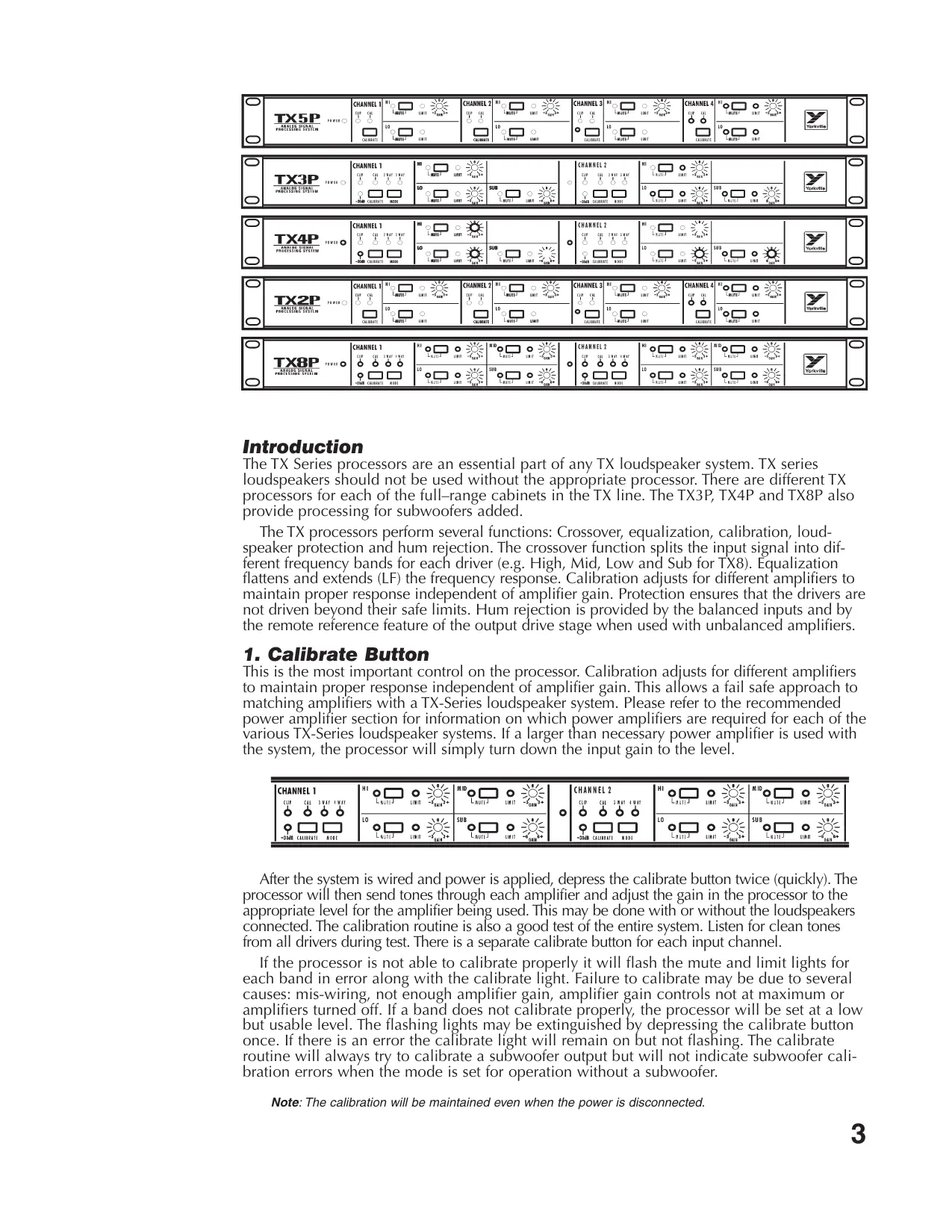
The TX Series processors are an essential part of any TX loudspeaker system. TX series loudspeakers should not be used without the appropriate processor. There are different TX processors for each of the full-range cabinets in the TX line. The TX3P, TX4P and TX8P also provide processing for subwoofoers added.
The TX processors perform several functions: Crossover, equalization, calibration, loud-speaker protection and hum rejection. The crossover function splits the input signal into different frequency bands for each driver (e.g. High, Mid, Low and Sub for TX8). Equalization flattens and extends (LF) the frequency response. Calibration adjusts for different amplifiers to maintain proper response independent of amplifier gain. Protection ensures that the drivers are not driven beyond their safe limits. Hum rejection is provided by the balanced inputs and by the remote reference feature of the output drive stage when used with unbalanced amplifiers.
1. Calibrate Button
This is the most important control on the processor. Calibration adjusts for different amplifiers to maintain proper response independent of amplifier gain. This allows a fail safe approach to matching amplifiers with a TX-Series loudspeaker system. Please refer to the recommended power amplifier section for information on which power amplifiers are required for each of the various TX-Series loudspeaker systems. If a larger than necessary power amplifier is used with the system, the processor will simply turn down the input gain to the level.
| CHANNEL 1 CLIP CAL 3-way 4-WAY O O O O O -20M8 CALINRATE MODE | H1 L MUTE J LIMIT J LO L MUTE J LIMIT J SUB L MUTE J LIMIT J -20M8 CALINRATE MODE | M ID L MUTE J LIMIT J SUB L MUTE J LIMIT J -20M8 CALINRATE MODE | O CHANNEL 2 CLIP CAL 3-WAY 4-WAY O O O O O O -20M8 CALINRATE MODE | H1 L MUTE J LIMIT J LO L MUTE J LIMIT J SUB L MUTE J LIMIT J -20M8 CALINRATE MODE |
After the system is wired and power is applied, depress the calibrate button twice (quickly). The processor will then send tones through each amplifier and adjust the gain in the processor to the appropriate level for the amplifier being used. This may be done with or without the loudspeakers connected. The calibration routine is also a good test of the entire system. Listen for clean tones from all drivers during test. There is a separate calibrate button for each input channel.
If the processor is not able to calibrate properly it will flash the mute and limit lights for each band in error along with the calibrate light. Failure to calibrate may be due to several causes: mis-wiring, not enough amplifier gain, amplifier gain controls not at maximum or amplifiers turned off. If a band does not calibrate properly, the processor will be set at a low but usable level. The flashing lights may be extinguished by depressing the calibrate button once. If there is an error the calibrate light will remain on but not flashing. The calibrate routine will always try to calibrate a subwoofer output but will not indicate subwoofer calibration errors when the mode is set for operation without a subwoofer.
Note: The calibration will be maintained even when the power is disconnected.
A default calibration may be done by holding down the calibrate button and then applying power to the processor. This will set the processor to approximate calibration. The default calibration should only be used when regular calibration fails and there is not enough time to find the fault. Use of the default calibration may leave the system vulnerable to damage.
Warning: Speaker damage may result if the processor is calibrated to a specific amplifier and another amplifier of larger power or greater input sensitivity is used.
ALWAYS RE-CALIBRATE THE SYSTEM WHEN A DIFFERENT AMPLIFIER IS USED.
Each frequency band of each channel may be muted with the corresponding mute button. The mute buttons are intended as an aid to tracing system problems and checking the system.
3. TX9S Mode
The TX3, TX4 and TX8 processors have an internal mode switch for use with the TX9S subwoofer. The processor cover must be removed in order to change between TX8S and TX9S. There is a red led that can be viewed from the back of the unit to confirm the mode of operation.
4. Mode Buttons
There are two operating modes: with a subwoofer and without a subwoofer. The TX8 system is 4-way with a subwoofer and 3-way without a subwoofer. The TX3 and TX4 systems are 2-way without a subwoofer and 3-way with a subwoofer. The TX2P and TX5P processors do not support subwoofoers and hence, do not have a mode switch.
5. 3-Way / 4-Way Indicators (TX8P)
These indicate the mode that the processor is currently in. 4-way is intended for use with a subwoofer. 3-way is for use without a subwoofer. This changes the equalization and low frequency rolloff of the LF output. The SUB out remains active in both modes.
6. 2-Way / 3-Way Indicators (TX3P, TX4P)
These indicate the mode that the processor is currently in. 3-way is intended for use with a subwoofer. 2-way is for use without a subwoofer. This changes the equalization and low frequency rolloff of the LF output. The SUB out remains active in both modes.
7. Trim Controls
The trim controls allow the user to make fine adjustments to the crossover gain for each band. The sub woofers can be adjusted +/- 6 dB while the other bands can be adjusted +/- 3 dB.
8. Power Indicator
This light indicates that the unit is receiving AC power from the mains supply.
9. Clip Indicator
This light indicates that the input is receiving too much signal, there is about 6dB headroom from the indicated level.
10. Activity Indicators
This light indicates that there is a signal on the input of about -30 dBV or more (TX3P, TX4P, TX8P).
11. Limit Indicators
These lights indicate that the limiters are active. They indicate even the slightest amount of limiting hence they go on early and have a slow release.
12. Mute Indicators
These indicate that the frequency band is muted.
13. Connections
Please refer to diagrams at the back of this manual.
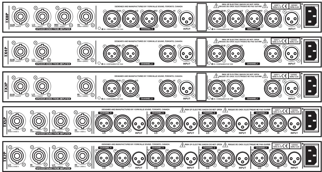
14. Inputs
The inputs connect to the signal source, this would normally be the last piece of equipment in the signal processing chain or the output of the mixer. Since the signal run to the processor is usually long, it is important that the equipment that feeds the run to the processor has a low output impedance, preferably with balanced output impedance. If the source is unbalanced ground the connection to pin 3 at the source.
15. Outputs
Since the processor should be in the same rack as the amplifiers these cables will be short cables to the amplifiers below. It is intended that one stereo amplifier be used for the same frequency band of 2 cabinets, but this is not essential.
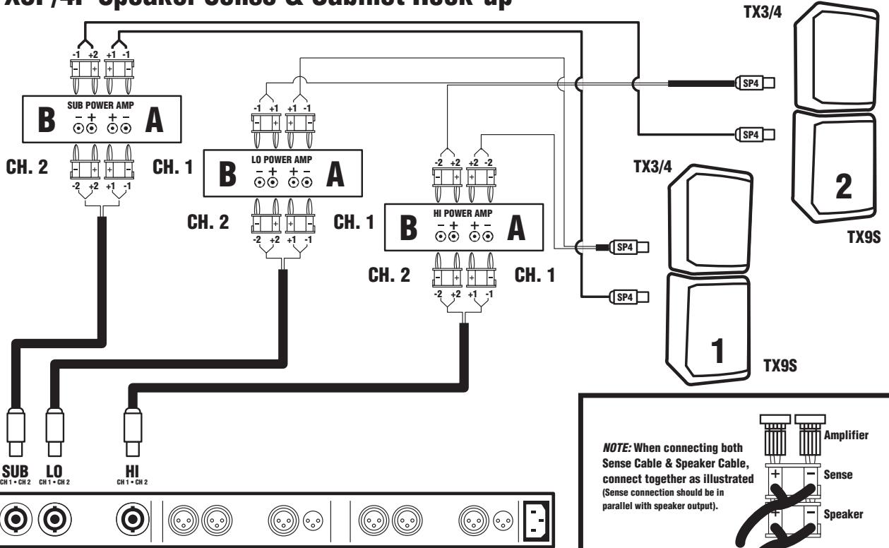
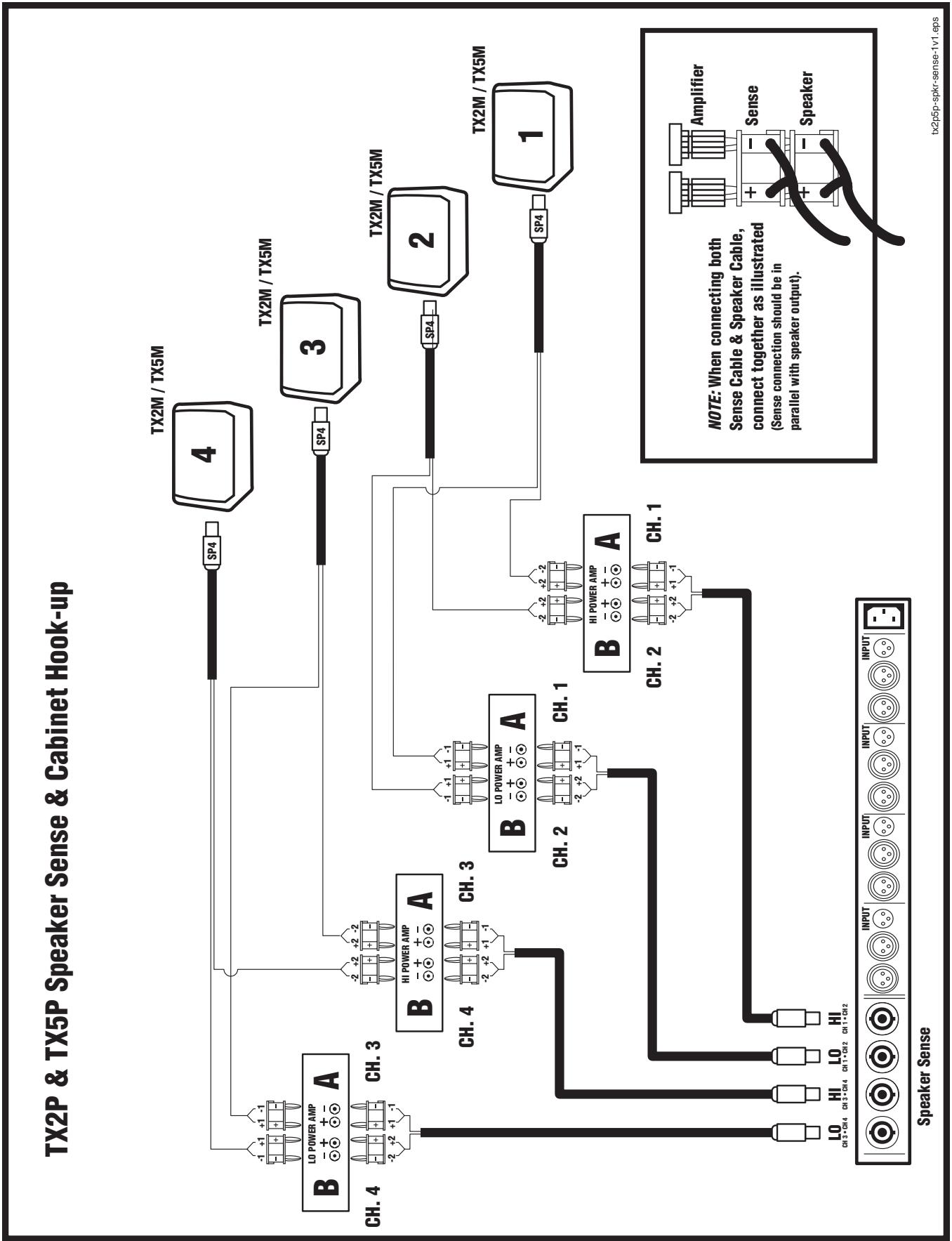
16. Sense Connections
The sense cables allow the processor to monitor the output level of the amplifiers. Each sense cable carries the same frequency band for 2 speaker cabinets. For example one cable would carry the signal from a stereo amplifier driving two HF drivers. If the amplifier has Speakon™ outputs for stereo/bridged mode cables, these outputs should connect direct from the amplifier to the processor.
NOTE: The processor will not calibrate if the Left & Right connections are reversed.
17. Modified Response (TX2P/TX5P)
In response to user recommendations, TX2P processors manufactured after 07/98 have a response that dip -6.5db at 750Hz and -4.5db at 250Hz . The response may be returned to the original, flattened response by turning the internal trim pots (Rt1a, b, c, and d) fully clockwise.
The TX5P features include a variable notch filter. The factory preset is 120Hz , -6db (fully Counter-Clockwise). This is set to help eliminate boominess. The response can be flattened by rotating the internal trim pots (Rt1a, b, c, and d) fully clockwise.
To access these trim pots, it is necessary to remove the chassis cover.
RECOMMENDED POWER AMPLIFIERS
| SYSTEM | HI | MID | LOW | SUB |
| TX8 | AP2020 or Equivalent (4 ohm Mode) | AP2020 or Equivalent (4 ohm Mode) | AP4040 or Equivalent | * For TX8S use AP4020 or Equivalent (Bridged mode) |
| TX4 | AP2020 or Equivalent (4 ohm Mode) | N/A | AP4040 or Equivalent | AP4020 or Equivalent |
| TX3 | AP2020 or Equivalent (4 ohm Mode) | N/A | AP2020 or Equivalent (4 ohm Mode) | AP4020 or Equivalent (Bridged mode) |
| TX2 | AP800 or Equivalent | N/A | AP2020 or Equivalent (4 ohm Mode) | N/A |
| TX5 | AP 2020 or Equivalent | N/A | AP4040 or Equivalent (4 ohm Mode) | N/A |
- Note: The TX8 can be used with TX8S or TX9S. TX8S requires 1800 watts. TX9S requires 2400 watts. Minimum recommended power, 1200W.
SUPPLEMENT
Introduction
TX processors all come with an owner's manual which covers the specifics of system setup. The purpose of this writing is to provide supplemental information for first-time TX users. As well, we realize that not everyone is accustomed to the demands of operating actively processed 2, 3 and 4-way speaker systems. We will therefore endeavor to get you started off the right way. Once the initial setup procedures are mastered, you should find that your TX system virtually runs itself - you do the mixing, TX does the sound.
The Processor - General:
In any advanced processed speaker system you will find certain elements. These include (1) electronic crossovers, (2) graphic and/or parametric equalizers and (3) compressor/limiters - all dedicated to speaker performance. The TX processor basically contains all three of these elements, but with an important difference. Unlike mix-and-match systems, each TX processor has been engineered in conjunction with the development of its designated speaker to ensure the absolute maximum performance. As a result, we do not recommend that you use any other processor. For example, if you have TX3's, use the TX3P, TX4's, use the TX4P, etc. Subwoofer processing is included in all processors but the TX2P and TX5P. A push-button subwoofer switch inside the processors selects TX8S or TX9S processing and an LED visible through a small hole in the back of the chassis illuminates for TX9S. If the LED is ON, TX9S processing is selected.
In addition to the above elements, your TX processor contains a special gain-sensing feature which works in conjunction with a pre-programmed calibration circuit. During the initial speaker setup and calibration, cables which you connect from the amplifier outputs back to "sense" inputs on the processor tell its internal auto-adjust feature where to set the input gain. This functions like an automatic amplifier volume control, hence it is important that the actual volume controls on your amplifiers always be set at maximum. After calibration is successfully completed, the processor will "remember" all its internal auto-adjustments and the procedure need not be repeated as long as you use those amplifiers. However, whenever you do substitute an amp, re-calibrate the system.
Amplifiers:
We specify certain Audiopro amplifiers in the TX manual. You may use others, however for maximum performance from the system, they should have not less than the following output;
| Model# | Component/s | Required Power per Channel |
| TX8 | Hi (2-inch) | 300 Watts @ 8 ohms |
| Mid (8-inch) | 300 Watts @ 8 ohms | |
| Lo(2x15-inch) | 1200 Watts @ 4 ohms | |
| TX4 | Hi (2-inch) | 300Watts @ 8 ohms |
| Lo (15-inch) | 600 Watts @ 8 ohms | |
| TX3 | Hi (2-inch) | 300 Watts @ 8 ohms |
| Lo (12-inch) | 300 Watts @ 8 ohms | |
| TX2M | Hi (2-inch) | 200 Watts @ 8 ohms |
| Lo (12-inch) | 300 Watts @ 8 ohms | |
| TX5M | Hi (2-inch) | 300Watts @ 8 ohms |
| Lo (15-inch) | 600 Watts @ 8 ohms | |
| TX9S/9S | Lo (2x18-inch) | 1800 to 2400 Watts @ 4 ohms (mono bridged) |
If the amplifiers are higher powered, the processor will detect this during calibration and simply adjust their input signal levels downward accordingly to maintain driver safety. And if one or more amplifiers are of considerably lower power than the design criteria, the CALIBRATE ERROR LED will flash along with all the other LED's for that frequency channel. It is advisable to use the recommended power, however if the power is marginally less than ideal, the processor will simply adjust its gain upward. Watch for amplifier clipping if this is the case (and generally, of course). Once again, be sure to turn all amplifier volume controls to maximum and leave them there.
Another possible problem, mixing up any left & right channel connections, will create a situation wherein the calibration will not work. If this happens, check your line and speaker level connections carefully to ensure that all the various left and right channel connections are consistent from the mixer to the TX processor to the power amps and back to the speakers.
Yorkville Speaker Cables and Connections:
Yorkville Sound offers a full range of 14 gauge speaker cables as well as the 20-gauge, Speakon-to-bananaplug SP4-3SB "sense" lead. The speaker cables are available with 4 or 8 leads and in 25, 50 & 100 foot lengths. All speaker cables come with Speakon connectors at the speaker ends and either Speakon or banana plug connectors on the amp ends. The banana plug ends have numbered labels on the wires for function as follows:
SP4, 4-element cables (for TX2,3,4,5, and subwooers) ... 1 = low frequency, 2 = high frequency
SP8, 8-element cables (for TX8) ... 1 = subwoofer, 2 = lows, 3 = mids, 4 = highs).
The banana plugs on Yorkville SP cables have a small tab on one side marked "ground" (in very small print). This represents negative (-) terminal so that you can maintain uniform polarity when connecting the cables to the amplifier. **Polarity is very important. The positive banana terminals on our amplifiers are grouped together for bridging purposes. But when you are not bridging them, which would be in most cases, the banana plug connected to either the A or B channel output posts will have to be turned upside-down so that the negative banana leads are connected to the negative output posts.
Other Speaker Cables:
Cables other than ours should be 14 gauge or heavier. If they have banana connectors on the amplifier ends, they should have clear markings on them for function and **polarity. To help you rig the Speakon ends, Speakon wiring inside the TX cabinets is as follows:
TX2,3,4,5 ... +1-1 = lows, +2-2 = highs
TX8 ... +2-2 = low (low mids), +3-3 = mids, +4-4 = highs
TX9S, TX9S = +1+2,-1-2
**(Note, it is very important for the performance of speaker systems that all similar drivers have the same polarity - in other words that the positive output terminals on the amplifiers are connected to the positive terminals on all the drivers. For example, adjacent woofers with different polarity can actually cancel each other's acoustic output by as much as -10dB. The effect is like losing a large percentage of your amplifier power. Similarly, acoustic phase alignment is important. For tips about setting up the speakers for maximum performance, read about "close coupling" under Speakers.)
Line Level Cables and Connections:
Cables running between the mixer and processor and the processor and power amplifiers must have XLR connectors at the TX end with applicable connectors at the other end. TX
processor inputs are female XLR's and the outputs are male XLR's. Most mixers now have balanced outputs using 1/4-inch TRS (tip-ring-sleeve) jacks or XLRs. Power amp inputs tend to be balanced these days too, but many of the old amplifiers still in use have unbalanced inputs. As well, certain older mixers may have unbalanced outputs. This is not a problem because TX processors are electronically balanced with a special "Remote Ground Reference" feature. With this feature, you can achieve the noise rejection of a totally balanced mixer-processor-amplifier setup even when the amp inputs or mixer outputs are unbalanced, usually just by employing the right type of patch cables. To achieve balanced-type noise rejection when connecting a TX processor to an unbalanced mixer or amplifier, use balanced, 3-element (2 centre leads plus shielding) patch or mic cables. In some cases, just doing this will provide balanced-type noise rejection. This is because manufacturers in the past have often used stereo input or output jacks, even though their amplifiers or mixers were unbalanced, and interconnected the ring and ground tabs internally. This is enough for the RGR system to work using regular balanced cables. However, if the mixer or amp does not have this feature and you find that simply using a balanced patch cord does not cut down on the hum or hiss, try rigging the following special cable:
Start with a balanced patch cord or mic cable with the appropriate male or female XLR on the TX end. Keep in mind that the TX processor's XLR wiring configuration is; pin 2 = tip (hot), pin 3 = ring (hot, reverse phase) & pin 1 = ground. Remove the stereo 1/4'' plug or XLR from the other end being sure to twist the wire previously from pin 3 and the ground shield wire together. Solder the "hot" in-phase wire from XLR pin 2 to the plug's hot tab (the shorter one). Now solder the twisted wires to the plug's ground lug and screw on the jacket.
Finally, mark that cable with tape for future use.
Speakers - Phased Arrays:
In addition to wiring up a TX system correctly, you need to be concerned with proper setup of the enclosures.
No more than the usual care need be taken if you are running a small system, say two TX3's and a TX9S on each side of the stage. However, if the system is larger and high sound pressure is the order of the day, perhaps at an outdoor concert or in a very large venue, you will need to array the enclosures so that their acoustic outputs are in phase.
Creating in-phase speaker arrays is basically a matter of keeping similar enclosures close together, facing in the same direction and aligned on the same horizontal plane. This is referred to as close-coupling. TX enclosures are trapezoidal so that similar ones, when close-coupled, create a semicircular array and thus provide a wide coverage angle. The TX9S subwoofoers should also be close-coupled when used in multiples - although they are not trapezoidal, low frequencies tend to be omni-directional and so they automatically have a wide coverage angle. The TX9S subwoofoers may be flown or freestanding and should be close coupled as well.
It is not generally advisable to close-couple dissimilar enclosures when they are reproducing the same frequency range. For example, you would probably not mix TX3's and TX4's close-coupled. The reason for this is that you will lose some of the potential additional sound pressure due to the enclosures' slightly different phase characteristics causing acoustic cancellations at various frequencies. This applies to all speaker systems. Subwoofoers also should not be mixed, and for the same reason. Mixing very different subwoofoers, for example horn-loaded and non-horn-loaded, can often result in a loss of low-frequency sound pressure because the phase characteristics are so very different. Once again, array similar enclosures for maximum reinforcement.
Flying Hardware:
TX8 3-way enclosures and the TX9S subwoofer come with slots to take 30-degree angled bars called BAR30s which lock in place with QUICKPINs to close-couple the enclosures side by side and hold them solidly together when flown in arrays. Other flying hardware includes SWIVLE-RINGs which lock into the upper and lower tracks for quick setup and teardown. They accept the cable eyes or shackles (our model SHACKLE3/8A). And for permanent installations, the upper and lower tracks will accept an EYEBOLT3/8A. To install this, simply remove the large Allen-head screw located in the bottom of the track about the midway mark and replace it with the eyebolt.
TX-SERIES
PROFESSIONAL LOUDSPEAKER SYSTEMS
SPECIFICATIONS
Function: Stereo, 3 or 4 way
Inputs: XLR Female (x2), 20 kohms
Inputs Full Power: +6dBu, +4dBv, 1.4Vrms
Max Input: +17dBu, +15dBv, 4Vrms
Outputs: XLR Male (x8), 600 ohm minimum
Output level: +14 dBu, +12dBv, 4Vrms
Sense Inputs: Speakon™ 4 (x4), Stereo one band per connector
Trim Controls: +/- 6dB for Sub, +/- 3dB for horn, mid & woofer
Approximate Crossover Points: 100 Hz, 300 Hz, 1200 Hz
TX3P & TX4P Processor
Function: Stereo, 2 or 3 way
Inputs: XLR Female (x2), 20 kohms
Inputs Full Power: +6dBu, +4dBv, 1.4Vrms
Max Input: +17dBu, +15dBv, 4Vrms
Outputs: XLR Male (x6), 600 ohm minimum
Output level: +14bBu, +12dBv, 4Vrms
Sense Inputs: Speakon™ 4 (x3), Stereo one band per connector
Trim Controls: +/- 6dB for Sub, +/- 3dB for horn & woofer
Crossover Points: TX4 1.3khz, 125Hz
TX3 1.3khz, 125Hz
TX2P & TX5P* Processor
Function: Quad (x4), 2 way
Inputs Full Power: +6dBu, +4dBv, 1.4Vrms
Max Input: +17dBu, +15dBv, 4Vrms
Outputs: XLR Male (x8), 600 ohm minimum
Output level: +14 dBu, +12dBv, 4Vrms
Sense Inputs: Speakon™ 4 (x4), Stereo one band per connector
Trim Controls: +/- 3dB for horn
Crossover Point: 1.8KHz / 1.3KHz^*


Introduction
TX9S, TX9S = +1+2,-1-2
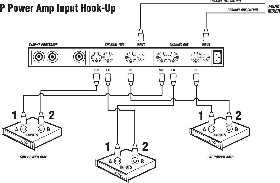
TX3P/4P Power Amp Input Hook-Up
LO POWER AMP
TX3P/4P Speaker Sense & Cabinet Hook-up
Speaker Sense
tx3-4-1v1.eps

Unlimited Warranty
Yorkville's two and ten-year unlimited warranty on this product is transferable and does not require registration with Yorkville Sound or your dealer. If this product should fail for any reason within two years of the original purchase date (ten years for the wooden enclosure), simply return it to your Yorkville dealer with original proof of purchase and it will be repaired free of charge. This includes all Yorkville products, except for the YSM Series studio monitors, Coliseum Mini Series and TX Series Loudspeakers.
Freight charges, consequential damages, weather damage, damage as a result of improper installation, damages due to exposure to extreme humidity, accident or natural disaster are excluded under the terms of this warranty. Warranty does not cover consumables such as vacuum tubes or par bulbs. See your Yorkville dealer for more details. Warranty valid only in Canada and the United States.
Garantie Illimitée
Voice: (905) 837-8481 Voice: (716) 297-2920
Fax: (905) 837-8746 Fax: (716) 297-3689

Niagara Falls, New York
14305 USA

WEB: www.yorkville.com
Niagara Falls, New York
14305 USA
Voice: (716) 297-2920
Fax: (716) 297-3689

Quality and Innovation Since 1963 Printed in Canada
Printed in Canada