ELITE ES700P - Powered speaker YORKVILLE - Free user manual and instructions
Find the device manual for free ELITE ES700P YORKVILLE in PDF.
User questions about ELITE ES700P YORKVILLE
0 question about this device. Answer the ones you know or ask your own.
Ask a new question about this device
Download the instructions for your Powered speaker in PDF format for free! Find your manual ELITE ES700P - YORKVILLE and take your electronic device back in hand. On this page are published all the documents necessary for the use of your device. ELITE ES700P by YORKVILLE.
USER MANUAL ELITE ES700P YORKVILLE
natural_image
Line drawing of a 3D rectangular device with a circular top and window-like cutout, no text or symbols present.MODEL TYPE: ES700P
ES700P
IMPORTANT SAFETY INSTRUCTIONS

This lightning flash with arrowhead symbol, within an equilateral triangle, is intended to alert the user to the presence of uninsulated "dangerous voltage" within the product's enclosure.
that may be of sufficient magnitude to constitute a risk of electric shock to persons.
The exclamation point within an equilateral triangle is intended to alert the user to the presence of important operating and maintenance (servicing) instructions in the
literature accompanying the appliance.
Instructions pertaining to a risk of fire, electric shock, or injury to a person
CAUTION: TO REDUCE THE RISK OF ELECTRIC SHOCK, DO NOT REMOVE COVER (OR BACK).
NO USER SERVICEABLE PARTS INSIDE.
REFER SERVICING TO QUALIFIED SERVICE PERSONNEL.
Read Instructions: The Owner's Manual should be read and understood before operation of your unit. Please, save these instructions for future reference and heed all warnings.
Clean only with dry cloth.
Packaging: Keep the box and packaging materials, in case the unit needs to be returned for service.
Warning: To reduce the risk or fire or electric shock, do not expose this apparatus to rain or moisture. Do not use this apparatus near water!
Warning: When using electric products, basic precautions should always be followed, including the following:
Power Sources
Your unit should be connected to a power source only of the voltage specified in the owners manual or as marked on the unit. This unit has a polarized plug. Do not use with an extension cord or receptacle unless the plug can be fully inserted. Precautions should be taken so that the grounding scheme on the unit is not defeated.
Hazards
Do not place this product on an unstable cart, stand, tripod, bracket or table. The product may fall, causing serious personal injury and serious damage to the product. Use only with cart, stand, tripod, bracket, or table recommended by the manufacturer or sold with the product. Follow the manufacturer's instructions when installing the product and use mounting accessories recommended by the manufacturer.
The apparatus should not be exposed to dripping or splashing water; no objects filled with liquids should be placed on the apparatus.
Terminals marked with the “lightning bolt” are hazardous live; the external wiring connected to these terminals require installation by an instructed person or the use of ready made leads or cords.
Ensure that proper ventilation is provided around the appliance. Do not install near any heat sources such as radiators, heat registers, stoves, or other apparatus (including amplifiers) that produce heat.
No naked flame sources, such as lighted candles, should be placed on the apparatus.
Power Cord
Do not defeat the safety purpose of the polarized or grounding-type plug. A polarized plug has two blades with one wider than the other. A grounding type plug has two blades and a third grounding prong. The wide blade or the third prong are provided for your safety. If the provided plug does not fit into your outlet, consult an electrician for replacement of the obsolete outlet. The AC supply cord should be routed so that it is unlikely that it will be damaged. If the AC supply cord is damaged DO NOT OPERATE THE UNIT.
Unplug this apparatus during lightning storms or when unused for long periods of time.
Service
The unit should be serviced only by qualified service personnel.
SUIVEZ TOUTES LES INSTRUCTIONS
text_image
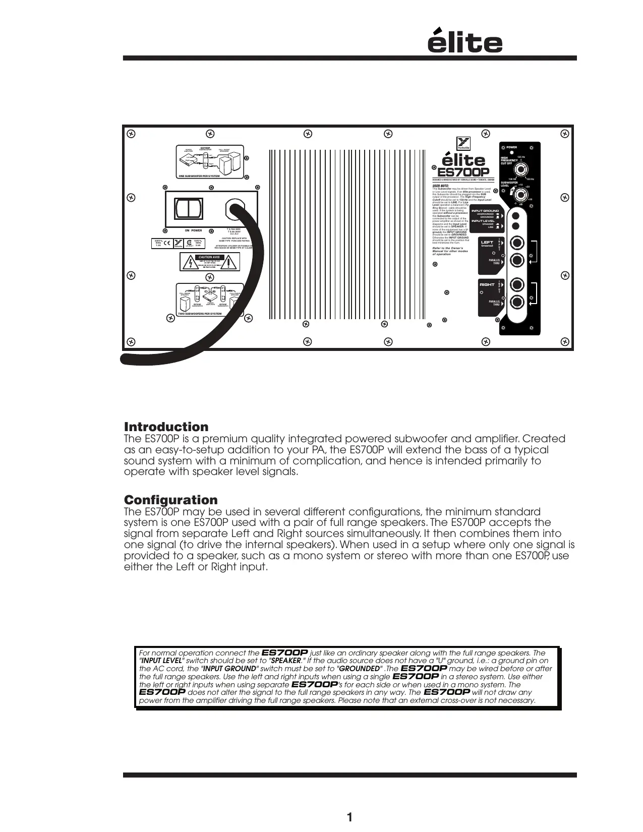
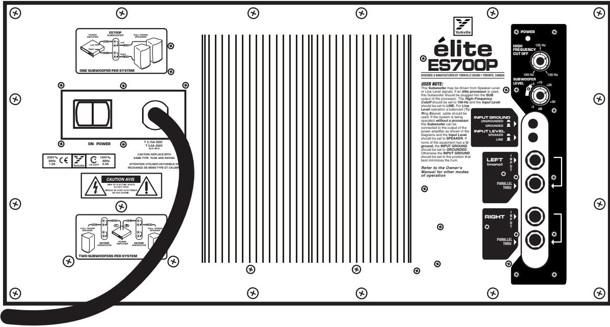
ON POWER T 3/16A GDC T 5/24 200V Auto-Stop CAUTION RESPLACE WITH SAME TYPE FUSE AND RATING ATTENTION TO BEATEN ON FORMS & RATING RECHANGE DE REMI TYPE ET CALIFORN CAUTION AVS TWO SUBWOOFERS PER SYSTEM Yorkville Elite ES700P DESIGNED A MANUFACTURED BY YORKVILLE SOUND + TORONTO, CHADAN USER NOTE: This Subwoofer may be driven from Speaker Level or Line Level signals. If an elite processor is used, this Subwoofer should be plugged into the SUB output of the processor. This High-Frequency Cutoff should be set to 150-Hz and the Input Level should be set to LINE. For Line Level operation a balanced (T) Ring Bracket cable should be used. If the system is being operated without a processor. this Subwoofer can be connected to the output of the power amplifier as shown in the diagnoses and the Input Level should be set to SPEAKER. If none of this equipment has a 1:1 ground, the INPUT GROUND should be set to GROUNDED. Otherwise the INPUT GROUND should be set to the position that best minimizes the hurt. Refer to the Owner's Manual for other modes of operation POWER HIGH FREQUENCY CUT OFF 125 Hz 150 Hz SUBWOOFER LEVEL 100 Hz +10 -20 INPUT GROUND GROUNDED INPUT LEVEL SPREAD LINE LEFT (Unloaded) PARALLEL THRU RIGHT PARALLEL THRUIntroduction
The ES700P is a premium quality integrated powered subwoofer and amplifier. Created as an easy-to-setup addition to your PA, the ES700P will extend the bass of a typical sound system with a minimum of complication, and hence is intended primarily to operate with speaker level signals.
Configuration
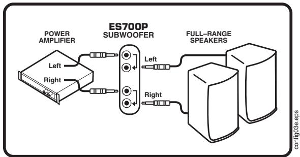
The ES700P may be used in several different configurations, the minimum standard system is one ES700P used with a pair of full range speakers. The ES700P accepts the signal from separate Left and Right sources simultaneously. It then combines them into one signal (to drive the internal speakers). When used in a setup where only one signal is provided to a speaker, such as a mono system or stereo with more than one ES700P, use either the Left or Right input.
For normal operation connect the ES700P just like an ordinary speaker along with the full range speakers. The "INPUT LEVEL" switch should be set to "SPEAKER." If the audio source does not have a "U" ground, i.e.: a ground pin on the AC cord, the "INPUT GROUND" switch must be set to "GROUNDED". The ES700P may be wired before or after the full range speakers. Use the left and right inputs when using a single ES700P in a stereo system. Use either the left or right inputs when using separate ES700P's for each side or when used in a mono system. The ES700P does not alter the signal to the full range speakers in any way. The ES700P will not draw any power from the amplifier driving the full range speakers. Please note that an external cross-over is not necessary.
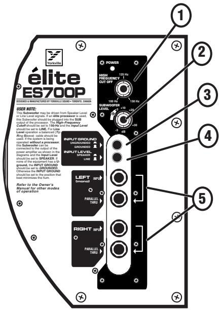
1. Hi Frequency Cutoff Control
This control varies the frequency at which the ES700P rolls off the high frequencies. This provides part of a crossover function. This crossover function also combines with the natural low frequency roll off inherent of the full range cabinet (when the ES700P is not used with an élite processor). This control should be set to the closest possible frequency to 20 Hz below the crossover point that the full range speakers processor uses as it's crossover point.
text_image
elite ES700P DISCIRED & MANUFACTURING BY TWALANCE SCORE • TRENDS CHAIN USER NOTE: This speaker may be driven from Speaker Level in Line Level signals. If an elite processor is used, this Subwoofer should be engaged into the RUB output of the processor. The High-Frequency Cable should be set to 180Hz on the Input Level should be set to LINE. For Line Level operation a broadcast (F2) Ring Shield: currents should be used in the output of the power amplifier as shown in the diagrams and the Input Level should be set to SPEAKER. If none of the equipment has a 5A ground, this INPUT GROUND should be set to GROUNDED. Otherwise the INPUT GROUND should be set to the position that set interfaces the fault. Forward for the Owner's Manual for other modes of operation. POWER HIGH FREQUENCY CUT OFF 173 Hz 100 Hz SURFACE RED LEVEL -3 dB +3 dB -3 dB INPUT GROUND UNGROUNDED GROUNDING This Subwoofer can be connected to the output of the power amplifier as shown in the diagrams and the Input Level should be set to SPEAKER. If none of the equipment has a 5A ground, this INPUT GROUND should be set to GROUNDED. Otherwise the INPUT GROUND should be set to the position that set interfaces the fault. LEFT General PARALLEL Taxes RIGHT General PARALLEL Taxesspl when set for speaker level input. With a typical full range companion speaker this will give flat response. In either line or speaker operation it will usually be desirable to set the control at +3 to +6 to give some bass boost at low power levels. At levels approaching full power the built-in limiter will automatically reduce the gain to prevent over powering the subwoofer. Operation with settings significantly above +12 may clip the circuitry in the subwoofer reducing the dynamics of the music. Setting
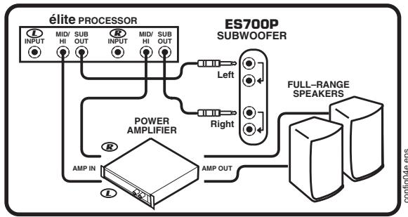
If an élite processor is used, set the high frequency cutoff to maximum (160 Hz)
the subwoofer gain above +12 is only appropriate at low operating level.
2. Subwoofer Level Control
The subwoofer level control adjusts the amount of bass added to the sound system by the ES700P. This adjusts for the relative sensitivity of the companion full range speakers and the desired system frequency response. This control should be set by listening while operating at a medium level and then not changed. It is not possible to set this control properly at high levels since the limiter is determining the output level. Setting the level too high will over load the circuitry causing a loss of bass dynamics. The level control should not be set above the 9 o'clock position except when operating at low levels. For most applications the control should be set between 0dB and +20dB.
A setting of 0dB on the SUBWOOFER LEVEL control is the correct starting point when setting up a sound system. From there the sound can be adjusted for best sound. The 0 dB mark refers to the setting that will give full power when the line input is used and the input signal is at a level of +4 dBV. This also is the setting to give a sensitivity of 2.83 Vrms (1 watt 8-Ohms) for 100 dB
3. Input Ground Switch
The ES700P expects the source feeding it to be grounded. A system comprised entirely of ungrounded equipment may cause the ES700P to hum or buzz. If you have a buzz or hum problem, try setting the switch to the "GROUNDED" position. The switch should otherwise be left in the "UNGROUNDED" position. Do not use the grounded position with an amplifier operating in bridged mode or when the sleeve of the input signal is live.
4. Input Level Switch
A switch is provided to switch input levels between speaker level and line level. The switch should be set to speaker level when the ES700P is fed from the output of an amplifier or powered mixer. The line level position is for when the ES700P is fed a signal from a processor, electronic crossover or the output of an unpowered mixer. When using the line level mode the use of balanced (Tip, Ring, Sleeve) cables will reduce the sensitivity to hum and buzz.
AT HIGH POWER LEVELS WHEN THE LIMITER IS OPERATING INCREASING THE SUBWOOFER LEVEL CONTROL WILL NOT INCREASE THE OUTPUT. DO NOT INCREASE SETTING WHILE OPERATING AT HIGH LEVELS.
5. Stereo Input & Parallel Thru Jacks
For normal operation, connect the ES700P just like an ordinary speaker, along with the Full-Range speakers and set the Input Level switch to SPEAKER. If the audio source does not have a ground pin on the AC cord, the Input Ground switch must be set to GROUND (GND). The ES700P may be plugged in before or after the Full-Range speakers. Use the Left and Right Inputs when using a single ES700P in a stereo system. Use either the Left or the Right inputs when using separate ES700P's for each side (or when used in a Mono system). The ES700P does not alter the signal to the Full-Range speakers, and will not draw any power from the host amplifier driving them. Please note that an external crossover is not necessary.
As well as accommodating the full range speakers, the PARALLEL THRU jacks allow many ES700Ps to be connected in a string (or otherwise in parallel). There is no practical limit to the number of ES700Ps that may be connected together.
6. Protection
The ES700P has circuitry to prevent clipping, over current and over excursion. The circuitry does not alter the frequency response as the level changes. At high levels the limiter will limit the gain of the ES700P and hence if the user attempts to set the subwoofer level control at high levels the resulting setting will be incorrect. The level control should be set while operating at low levels (under 10 watts). If the level control is set to high due to setting it at high operating levels the input circuit will clip and the dynamics of the bass will be lost. This can happen without audible distortion since the filters will filter out the distortion.
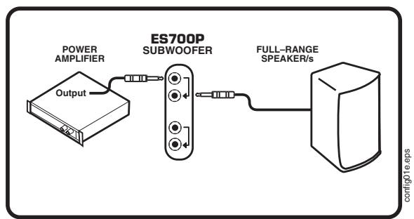
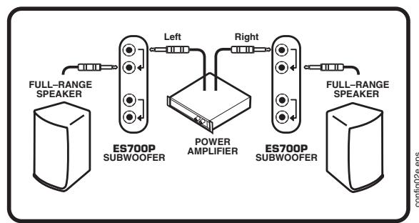
ES700P Configuration Examples
flowchart
graph LR
    A["Power Amplifier"] --> B["ES700P SUBWOOFER"]
    B --> C["FULL-RANGE SPEAKER/s"]
    D["Output"] --> B
ONE SUBWOOFER, WITH MONO SYSTEM
flowchart
graph LR
    A["FULL-RANGE SPEAKER"] --> B["ES700P SUBWOOFER"]
    B --> C["POWER AMPLIFIER"]
    C --> D["ES700P SUBWOOFER"]
    D --> E["FULL-RANGE SPEAKER"]
    B --> F["Left"]
    D --> G["Right"]
TWO SUBWOOFERS PER SYSTEM
flowchart
graph LR
    A["POWER AMPLIFIER"] -->|Left| B["ES700P SUBWOOFER"]
    A -->|Right| B
    B -->|Left| C["FULL-RANGE SPEAKERS"]
    B -->|Right| C
    C --> D["Server"]
ONE SUBWOOFER, WITH STEREO SYSTEM
flowchart
graph TD
    A["ES700P SUBWOOFER"] -->|Left| B["FULL-RANGE SPEAKERS"]
    A -->|Right| C["POWER AMPLIFIER"]
    C -->|AMP IN| D["Power Amplifier"]
    C -->|AMP OUT| E["Full Range Speaker"]
    A --> F["Elite PROCESSOR"]
    F --> G["INPUT MID/ SUB OUT MID/ SUB OUT"]
    F --> H["HI"]
    F --> I["OUT"]
    style A fill:#f9f,stroke:#333
    style B fill:#ccf,stroke:#333
    style C fill:#cfc,stroke:#333
    style D fill:#fcc,stroke:#333
    style E fill:#cff,stroke:#333
    style F fill:#ffc,stroke:#333
    style G fill:#cfc,stroke:#333
    style H fill:#cfc,stroke:#333
    style I fill:#cfc,stroke:#333
ONE SUBWOOFER USING ÉLITE PROCESSOR

élite
ES700P
Specifications
Power Requirements
120V: 117V-120V AC 60 Hz 2.5A
230V: 230VAC 50 Hz 1.3A
Power Amplifier Power (internal): 700 Watts
Frequency response: 45 Hz to 125 Hz
Input Impedance: 80 kOhms
Speaker components: 2 x 10 inches
Input Connections
Tip: Positive (+ve)
Ring(Shaft): Negative (-ve)
Grounding
The sleeves of the input are not grounded except when the input ground switch is set to GND. Grounding is done through a 100-Ohm protection device in order to prevent damage due to miswiring.
Limiting
Clipping, excursion and average voice coil current, thermal
Maximum SPL
131 dB (60 Hz to 110 Hz)
Weight
93 lb. (42 kg)
Dimensions
(WxDxH): 24" x 24.5" x 17.5" 61 cm x 62.1 cm x 44.5 cm
Note: The ES700P built-in stand mounting adapter can be used with Yorkville SW-Teletube accessory to support our E160 cabinets. The support tube can be adjusted up to it's full 5-foot 4-inch extension safely as long as the ES700P is not inclined more than 10^ (10-degrees).
WARNING: Larger or heavier cabinets should not be used!
text_image
ESTOP SUBWOOFERS ONE SUBWOOFER PER SYSTEM ON POWER T.51A GDC T.5A 200V SAT-800 CAUTION REPLACE WITH SAME TYPE FOSE AND RATING ATTENTION: UTILISIN UN PULSE OF RECHANGE DE MEMI TYPE ET CALIBUS CAUTION AVS FOR SUBWOOFERS PER SYSTEM TWO SUBWOOFERS PER SYSTEM élite ES700P DESIGNED & MANUFACTURED BY FORVELLE SOUND • TORONTO, CANADA USER NOTE: This Subwoofer may be driven from Speaker Level of Line Level signals. If an elite processor is used, this Subwoofer should be plugged into the SUB output of the processor. This High-Frequency Cutoff should be set to 156 Hz and the Input Level should be set to LINE. For Line Level operation a balanced (Top) Ring Boxwell cable should be used. If the system is being operated without a processor. the Subwoofer can be connected to the output of the power amplifier as shown in the diagrams and the Input Level should be set to SPEAKER. If none of the equipment has a U- ground, the INPUT GROUND should be set to GROUNDED. Otherwise the INPUT GROUND should be set to the position that best minimizes the hum. Refer to the Owner's Manual for other modes of operation POWER HIGH FREQUENCY 125 Hz 100 Hz SUBWOOFER LEVEL +10 dB +30 dB INPUT GROUND GROUNDED GROUNDED INPUT LEVEL SPEAKER LINE LEFT DRUGED PARALLEL THRU RIGHT PARALLEL THRUIntroduction
text_image
élite ES700P DESIGNED & MANUFACTUR BY TORMILLA LEONE - TORRES, CHAWA USER NOTE: This Subcarrier may be driven from Speaker Level of Line Level signals. If a elite processor is used, this Subcarrier should be set up the BLB output of the processor. The High-Frequency Cable should be set to LINE. For Line Level operator a balanced (Fb Ring Slower) cable should be used if the system is being opened without a processor the Subcarrier can set the the power amplifier as shown in the diagrams and the brand level should be set to SPEAKER. If none of the equipment has a 1st grounded, the INPUT GROUND should be set to GROUNDED. Otherwise the INPUT GROUND should be set to the position that best minimizes the hum. Refer to the Owner's Manual for either mode of operation POWER HIGH FERREQUENCY OUT OFF SUPERVISOR LEVEL -100 Hz +100 Hz -200 Hz -300 Hz INPUT GROUND UNGROUNDED GROUNDRED INPUT LEVEL SPREADS LINE LEFT GRASSSED PARALLEL THOSE RIGHT INFRY PARALLEL THOSETwo & Ten Year Warranty
Unlimited Warranty
Yorkville's two and ten-year unlimited warranty on this product is transferable and does not require registration with Yorkville Sound or your dealer. If this product should fail for any reason within two years of the original purchase date (ten years for the wooden enclosure), simply return it to your Yorkville dealer with original proof of purchase and it will be repaired free of charge. This includes all Yorkville products, except for the YSM Series studio monitors, Coliseum Mini Series and TX Series Loudspeakers.
Freight charges, consequential damages, weather damage, damage as a result of improper installation, damages due to exposure to extreme humidity, accident or natural disaster are excluded under the terms of this warranty. Warranty does not cover consumables such as vacuum tubes or par bulbs. See your Yorkville dealer for more details. Warranty valid only in Canada and the United States.
Garantie Illimitée
Voice: (716) 297-2920
Fax: (716) 297-3689

text_image
Yorkvillewww.yorkville.com
Yorkville Sound
550 Granite Court
Pickering, Ontario
L1W-3Y8 CANADA
Yorkville Sound Inc.
4625 Witmer Industrial Estate
Niagara Falls, New York
14305 USA

natural_image
World map illustration with horizontal black lines, no text or labels presentWEB: www.yorkville.com
Niagara Falls, New York
14305 USA
Voice: (716) 297-2920
Fax: (716) 297-3689