
POWERMAX 1622 - Generator YORKVILLE - Free user manual and instructions
Find the device manual for free POWERMAX 1622 YORKVILLE in PDF.


| Product Type | Powered Mixing Console (amplified mixer) |
| Brand | YORKVILLE |
| Model | POWERMAX 1622 |
| Main Output Power | 800 W RMS at 4 Ω, 450 W RMS at 8 Ω |
| Monitor Output Power | 275 W RMS at 4 Ω, 140 W RMS at 8 Ω |
| Number of Input Channels | 16 channels (6 mono with overload protection + 4 stereo) |
| Main Equalizer | 9-band stereo (63 Hz – 16 kHz, +/- 12 dB) |
| Monitor Equalizer | 2 x 9-band mono (63 Hz – 16 kHz, +/- 12 dB) |
| Channel Equalizer | 3-band (mono channels): Low, Mid with sweep (100 Hz – 8 kHz), High |
| Digital Effects Processor | Built-in, 255 presets in stereo or 2 x 16 in mono mode |
| Phantom Power | 48 V on channels 1 to 12 |
| Protection | Overload limiters, thermal protection, short-circuit protection |
| Input Connectors | Balanced XLR, balanced 1/4" TRS, unbalanced RCA |
| Output Connectors | Speakon and 1/4" for speakers, balanced line outputs |
| Headphone Output | 1/4" with adjustable volume |
| Power Supply | 120 VAC, 60 Hz (standard model); 230 VAC, 50 Hz (export) |
| Power Consumption | Less than 1440 W |
| Weight | 30.8 kg |
| Ventilation | Two variable speed DC fans |
| Warranty | 2 years (electronics) / 10 years (cabinet) |
Frequently Asked Questions - POWERMAX 1622 YORKVILLE
User questions about POWERMAX 1622 YORKVILLE
0 question about this device. Answer the ones you know or ask your own.
Ask a new question about this device
Download the instructions for your Generator in PDF format for free! Find your manual POWERMAX 1622 - YORKVILLE and take your electronic device back in hand. On this page are published all the documents necessary for the use of your device. POWERMAX 1622 by YORKVILLE.
USER MANUAL POWERMAX 1622 YORKVILLE
2150 WATT STEREOMIXING CONSOLE

MODEL TYPE:YS1011
OWNER'S MANUAL
This lightning flash with arrowhead symbol, within an equilateral triangle, is intended to alert the user to the presence of uninsulated "dangerous voltage" within the product's enclosure
that may be of sufficient magnitude to constitute a risk of electric shock to persons.
The exclamation point within an equilateral triangle is intended to alert the user to the presence of important operating and maintenance (servicing) instructions in the ccompanying the appliance.
Instructions pertaining to a risk of fire, electric shock, or injury to a person
CAUTION: TO REDUCE THE RISK OF ELECTRIC SHOCK,DO NOT REMOVE COVER (OR BACK).
NO USER SERVICEABLE PARTS INSIDE.
REFER SERVICING TO QUALIFIED SERVICE PERSONNEL.
Read Instructions: The Owner's Manual should be read and understood before operation of your unit. Please, save these instructions for future reference and heed all warnings.
Clean only with dry cloth.
Packaging: Keep the box and packaging materials, in case the unit needs to be returned for service.
Warning: To reduce the risk or fire or electric shock, do not expose this apparatus to rain or moisture. Do not use this apparatus near water!
Warning: When using electric products, basic precautions should always be followed, including the following:
Power Sources
Your unit should be connected to a power source only of the voltage specified in the owners manual or as marked on the unit. This unit has a polarized plug. Do not use with an extension cord or receptacle unless the plug can be fully inserted. Precautions should be taken so that the grounding scheme on the unit is not defeated.
Hazards
Do not place this product on an unstable cart, stand, tripod, bracket or table. The product may fall, causing serious personal injury and serious damage to the product. Use only with cart, stand, tripod, bracket, or table recommended by the manufacturer or sold with the product. Follow the manufacturer's instructions when installing the product and use mounting accessories recommended by the manufacturer.
The apparatus should not be exposed to dripping or splashing water; no objects filled with liquids should be placed on the apparatus.
Terminals marked with the "lightning bolt" are hazardous live; the external wiring connected to these terminals require installation by an instructed person or the use of ready made leads or cords.
Ensure that proper ventilation is provided around the appliance. Do not install near any heat sources such as radiators, heat registers, stoves, or other apparatus (including amplifiers) that produce heat.
No naked flame sources, such as lighted candles, should be placed on the apparatus.
Power Cord
Do not defeat the safety purpose of the polarized or grounding-type plug. A polarized plug has two blades with one wider than the other. A grounding type plug has two blades and a third grounding prong. The wide blade or the third prong are provided for your safety. If the provided plug does not fit into your outlet, consult an electrician for replacement of the obsolete outlet. The AC supply cord should be routed so that it is unlikely that it will be damaged. If the AC supply cord is damaged DO NOT OPERATE THE UNIT.
Unplug this apparatus during lightning storms or when unused for long periods of time.
Service
The unit should be serviced only by qualified service personnel.
SUIVEZ TOUTES LES INSTRUCTIONS
Welcome to POWERMAX, possibly the most advanced, most powerful, mixer / amplifier in the world. Comprehensive mixing facilities are combined with a choice of...
- 255 onboard digital effects presets (or dual digital effects systems with 16 presets each)
- A speaker processor
- Four built-in power amplifiers with over 2,150 Watts in total
- Three graphic EQ's, channel EQ with sweepable mids
- Channel input overload protection
- Solo and mute functions and much more...
This manual will outline all the various functions and how they interact. Realizing that some POWERMAX users may be unfamiliar with certain features, we include user tips and additional information, which appears separately in the applicable sections.
For general information about mixing and other facets of sound-reinforcement check out our P.A. User Guide available on the net... (http://www.yorkville.com).
Input Channel Features
Input Overload Protection
Mono input channels 1 to 6 in the POWERMAX-16 (1 to 12 in the POWERMAX-22) feature CHANNEL OVERLOAD PROTECTION - a sonically transparent limiting function suitable for sources such as bass guitar or bass amp, bass drum, mics, pop-prone vocal mics, feedback-prone mics (e.g. for flattop guitar, and other troublesome sources).
Each channel features a PROTECT LED to indicate when the overload protection is working. A single DEFEAT button switches this feature on all groups of six channels simultaneously.
INSERT Jacks
The remaining mono channels feature INSERTJacks. These are 1/4-inch Tip-Ring-Sleeve (TRS) connec
tors, which combine, send and return functions for patching outboard signal processing directly into a channel. A suitable patch cable for this function (e.g. the Yorkville model PC-6iSPH) would consist of a single TRS (stereo) 1/4-inch plug and two lengths of shielded cable with a common ground branching to two regular (mono) 1/4-inch plugs. The TRS wiring is Tip = send, Ring = return and Sleeve = ground. Since the PC-6iSPH comes with the leads marked Tip and Ring, you would connect the Tip plug to the input of the signal processor (EQ, compressor, echo, etc.) and connect the Ring plug to the processor's output. The TRS (stereo) plug would go into the INSERT jack. The send function is post-GAIN and post-HPF (high-pass-filt

Alternatively, the INSERT jack may be employed to send a channel to a powered monitor (some people want to hear only themselves). Simply use an unbalanced shielded patch cable – in this one case, a balanced cable will not work. Be sure to insert the plug only to the first "click" when using the INSERT as a channel send, otherwise the signal will be interrupted and the channel will not work. If this happens, you have inserted the plug too far. Simply pull the plug out gently to the first stop.

MIC Inputs
The POWERMAX active input circuitry will accept microphones with impedances ranging from 50 ohms to 10,000* ohms. All low impedance mics will be compatible. Phantom power, covered under PHANTOM POWER Switch and LED, later on in the manual, is available on all MIC inputs when activated. Although this feature is for condenser microphones, dynamic mics may be connected while it is activated with no ill effects.
- Although it would be customary to plug high impedance mics into the BAL LINE jacks, most of them will also work in the MIC inputs, provided the mic's built-in XLR connections are pin 1 and pin 2. Simply use low impedance XLR to XLR mic cables.
PHANTOM POWER Switch and LED
48 Volt PHANTOM POWER is available on channels 1 through 12 on the POWERMAX-16 (1 through 18 on the POWERMAX-22). The PHANTOM power ON/OFF button is located on the front of the mixer, beside the HEADPHONE jack and the PHANTOM POWER LED is in the upper right area of the control panel.
Phantom power is available for condenser microphones. It may be applied to channels with regular dynamic mics connected with no problems. When connecting mics it is safest to turn off phantom power to avoid loud pops.

BAL LINE Inputs
Mono line-level sources, e.g. amplifier line outputs and high-impedance mics, can be connected to the mono or stereo channels via these jacks (use the L/MONO jacks on the stereo channels). Stereo tape decks and CD-players may be connected to the BAL LINE inputs on the stereo channels. RCA connectors are also provided to simplify this operation. It is possible to connect stereo sources to the mono channels, however you will need to plug the L&R signals into separate channels to avoid the risk of intermodulation distortion (i.e. do not "Y" them into one BAL LINE jack).
- The balanced connector references are: Tip (or XLR pin 2) = hot, in phase; Ring (or XLR pin 3) = hot, reverse phase; Sleeve (or XLR pin 1) = ground
You may connect an unbalanced source to any of the BAL LINE inputs with a regular unbalanced shielded patch cable. A slight modification to a balanced patch cable will help achieve noise cancellation when connecting POWERMAX to an unbalanced unit.
Simply undo one end of a balanced patch cord and de-solder the wire from the ring tab, then resolder the wire to the shield tab making sure that it does not touch anything else. Now re-assemble the plug and mark it with some tape for future reference. This will be the end that you plug into the unbalanced unit (this will also work with an RCA connector).
The L & R BAL LINE inputs on the STEREO channels are wired together internally so that a single (mono) signal connected to the L / MONO input will also be patched over to the R input (as long as nothing is plugged into the R jack). This simplifies connecting a mono source should the need arise (perhaps all the mono channels are taken).
In addition to being able to connect either a stereo or mono source to these jacks, you may alternately connect two different mono sources to them and use the BALANCE control to regulate their relative volumes. For example, a guitar amp line-output and a keyboard amp line-output could be connected and mixed this way. However, now you must also convert the POWERMAX to mono operation, otherwise one instrument will only come out the left speakers and the other only through the right speakers. Mono conversion is accomplished simply by plugging a "Y" patch cable from the L / MONO (left main) LINE LEVEL OUTPUT to the AMP A & B AMPLIFIER INPUTS. Now both main power amps will be receiving identical signals. See under PAN Control for another user tip regarding mono operation.
CD/TAPE Inputs (Stereo Channels Only)
These RCA connectors are included for convenience since many CD-players and tape decks have RCA outputs. Because it is primarily a live audio mixer, POWERMAX does not have an RIAA phono input circuit.
As a rule you would connect a tape deck or CD-player to either the CD / TAPE inputs or the 1/4" BAL LINE inputs, but not both. However, connecting sources to both sets – say, a tape deck to the CD/ TAPE inputs and a CD-player to the BAL LINE inputs on the same channel – will work. Naturally there will not be any separate level control for one or the other so the source with the strongest output signal or highest output impedance will be louder. If you are not running both sources at once, this won't be a problem. In any case there will be no loading distortion or other ill effects.
HPF Button
Situated at the top of the mono channel strips, this button switches a High-Pass Filter in and out representing a bass rolloff of 18dB per octave below 80Hz . The stereo channels do not have this feature, as they would usually be carrying recorded material.
The HPF (High-Pass Filter) is useful for controlling unwanted low-frequency spillover pickup by mics located too close to the bass drum, bass amp or the keyboard amp. It is also effective in regulating acoustic guitar pickups that are too boomy sounding (the lowest note on a concert-tuned guitar is 81.2Hz, so you aren't losing anything by rolling off the input response below 80Hz). Additionally, the HPF works to reduce pops and thumps from vocal mics. In fact, Any mic or pickup which reflects a source that does not go below 80Hz should have the HPF activated. This includes most wind instruments, most male voices, nearly all female voices and all drum mics except for kickbass. Why roll off the bass on these channels? ...because you will obtain added clarity and improve the system's gain before feedback.
GAIN Control
POWERMAX features active input circuitry with exceptionally high headroom. The GAIN control regulates the channel gain level to match it with the input signal strength. There are two gradation circles, the outer one (minus 20dB to plus 56dB) for the MIC input, the inner one (minus 36dB to plus 40dB) for the BAL LINE input. Since this control has a range of 70dB, it presents the user with considerable variability given the slightest amount of movement. You may need to become familiar with this aspect of the mixer.
A quick way to ensure that the GAIN is adjusted correctly is to turn it up during a sound check until the CLIP LED begins to flash (keep the channel fader at a safe, low setting during this process), then turn the GAIN down slightly. POWERMAX's CLIP LED drive circuits are preset to fire at -6dB below the onset of actual clipping so you need not worry about seeing some activity on the lights. You will find that this or any system performs more cleanly and quietly with the GAIN controls all set properly. Also, you may use PFL (Pre-Fade Listen) and the VU meter to set 0dB.
Channel EQ
The mono channels feature 3-band EQ +/-15dB. Mids are swept from 80Hz to 8kHz with 2.5kHz highlighted in the graphics as (our) standard mid frequency. The HIGH EQ is shelving at 12kHz and LOW EQ shelves at 80Hz. The stereo channel EQ is 4-band +/-15dB with fixed mids at 250Hz and 2.5kHz. +/-15dB and LOW EQ are the same as the mono channels.
Setting the channel EQ, like setting the GAIN levels, is best done during a sound check. In this case however, the less you vary things above or below "0," the better. +/-15dB represents considerable level change. If for example, you need to turn down the HIGH EQ on a channel, perhaps due to a persistent feedback problem with that mic, you may need to counter-adjust the level fader. In any case, big boosts are probably best avoided.
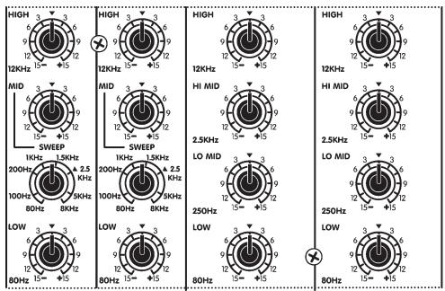
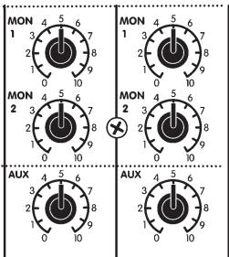
One cure for a bad feedback problem is to insert (see INSERT Jack) a graphic or parametric EQ into the problem channel and adjust it to attenuate only the feedback frequency. That way, fewer innocent frequencies will be affected. However, the channel EQ's MID SWEEP control can often be used quite effectively to perform a similar function. Simply set the MID at about -6dB then rotate the SWEEP control until the feedback stops. Now turn the MID up slightly to normalize the frequency response as much as possible without feedback.
MON1 & MON2 Sends
These are pre-fade, post-EQ sends. Internal routing is...
- to the MON masters and SOLO buttons
- to the MON1 and 2 EQs
- to the MON1 and 2 LINE LEVEL OUTPUTS
- through the cutoff switches in the AMP C and D AMPLIFIER INPUTS
- to the built-in, 275-Watt amplifiers C&D and finally
- to the MON1 and 2 POWER AMPLIFIER OUTPUTS.
Dual monitor systems permit setting up two zones of coverage. Certain channels may be isolated through one system or at least mixed extra loudly through it. For example the vocalists might want to hear themselves predominantly through their monitors. The other system might carry a more generalized mix for the rest of the band's monitors. Remember that the channel MON1&2 send controls are affected by the channel EQ, but NOT the fader. When feedback sets in, it's often the monitors, not the mains, although it comes through both systems so it's hard to tell. When it happens, turn down the suspect channel's MON sends. You'll probably kill the feedback and that channel's level through the main PA can remain unchanged. Now you can adjust the MON1 or MON2 EQ then turn that channel's MON send back up (carefully, you may still have some EQ-ing to do).
AUX Send
The channel AUX send is post-EQ & post-fader. Internal routing is
- to the AUX SEND master and CLIP LED, and
- to the AUX SEND jack.
Since the AUX sends are post-fader, any changes to the channel fader levels will result in changes to the AUX send levels. Therefore the AUX sends are useful for adding external effects (there are also stereo AUX RETURNS,) and for mono recording purposes such as speeches, a demo record rhythm track, etc. which do not require effects or graphic-EQ (this is a pre-effects, pre-EQ dry signal).
EFX1 & 2 Sends
Like the AUX send, these are post-fader and post-EQ. The EFX1 send is internally routed...
- to the EFX1 SEND master fader,
- to the internal digital effects system and EFX MODE switch,
- to the EFX1 RETURN masters.
The EFX2 send is routed
- to the EFX2 SEND master fader, and (simultaneously)
- to the EFX2 SEND jack and the EFX MODE button below the effects select dials.
POWERMAX effects can operate either as two discreet mono effects systems with sixteen presets each, or as a single stereo system with a total of 255 presets. In MONO mode you can, for example, have reverb on the EFX1 system and a special effect on EFX2. These would be mixed together on the main and monitor signals by the EFX RETURN to L&R and MON1 & 2 masters.

To get started, figure out which channels you want effects on (e.g. vocals, lead guitar, horns and keyboards - probably not on drums and bass). During a sound check, turn up the EFX1 send controls on those channels about halfway at first and push up the channel level faders also about halfway. Next, go to the lower right area of the control panel and set the EFX MODE switch to STEREO - the STEREO LED will illuminate (we are starting out with stereo effects, you can experiment with the dual MONO effects later). Now dial in the desired effect using the EFX SELECT and MODIFY controls - the menu of presets for STEREO operation appears below the dials. Next, turn up the EFX1 L&R (main system) RETURN LEVELS master about halfway. Now push up the L&R main master faders to a moderate listening level, as well as the EFX1 send master. Finally, re-adjust the channel EFX1 send levels to add or subtract the effects intensity in the main mix. Alternatively, you may preview the effects through headphones using the SOLO buttons covered later on. To preview the effects on the monitor mixes, plug in headphones (jack located at very front of mixer, right side below the arm rest) depress the MON1 and/or MON2 SOLO buttons, set the SOLO MODE to PFL and turn up the HEADPHONE master.
- The channel EFX1 send controls are exclusively for the internal effects system.
The channel EFX2 send controls allow you to add external or internal effects. With no external effects units connected between the EFX2 SEND jack and L/R RETURN jacks, and with the master EFX MODE button set for MONO (choice of 16 presets), the internal EFX2 system will be available to the mains and monitors. Simply set the EFX2/MODIFY dial for the desired effect according to the menu appearing above that dial, then adjust the EFX2 SEND and RETURN masters to blend in the effect with the straight signals. Use headphones and the MON1 and/or MON2 SOLO buttons to listen to the effects mix in the monitor system. The MONitor SOLO works the same with the AFL (After-Fader-Listen) and the PFL (Pre-Fader-Listen).
With the EFX MODE button set for STEREO, the channel EFX2 send controls will appear not to function, however they still do. EFX2 send signal is available at the EFX2 SEND jack and is regulated by the EFX2 SEND master fader. You may now connect external effects between the SEND and RETURN jacks, or you may alternately use the SEND jack to supply mono recording or broadcast signals not requiring effects (like the AUX signal, EFX2 is dry and post-channel fader).
When employing an external effects unit, connect the EFX SEND jack to the input of the unit and the EFX RETURN jacks to its outputs. If it is not a stereo effect, connect its output to the L / MONO EFX2 RETURN jack only. The effect unit's output may be previewed through headphones with the EFX2 SOLO button depressed and the SOLO MODE button in PFL position. AFL gives you EFX2 to MAIN RETURN level
PAN Control (Mono Channels)
This regulates the post-fader channel signal routing to the L&R main faders. Signal levels are compensated at the L&R rotation extremes so that panning during a performance will result in minimal SPL losses in the center-field audience areas.
In a stereo setup, the PAN controls would normally be set at or near center so audience members on both sides can hear everything properly. However if stereo is not an essential part of your PA sound, you might opt to convert POWERMAX to mono operation. To accomplish this, simply patch the L / MONO (left main/mono) LINE LEVEL OUTPUT into both the AMP A and AMP B AMPLIFIER INPUTS with a standard "Y" cable. Now, both main power amps are receiving a mono mix. This will enable you to use the PAN controls to set up two submaster groups – for example you could pan all the drum channels left and all the rest right. Now the L&R master faders become group masters. These master faders are placed close together, so it is easy to move them both at once when making main system level changes.
BALance Control (Stereo Channels)
This regulates both the channel output routing to the L&R main faders and the comparative levels of the stereo signals within the channel. If you have patched for mono operation (see PAN control above) it is possible to connect two different mono line-level sources to a stereo channel and use the BAL control to regulate their relative volumes. For more on this, see under BAL LINE INPUTS.
CLIP/MUTE Light
The CLIP LED is triggered at -6dB below the channel's actual clipping level. When the MUTE button is depressed, the CLIP light will come on at half-brightness and will still flicker to indicate clipping. With the CLIP light threshold set below actual clipping level, it is possible to allow a certain amount of light activity without worrying about distortion. As a result, you may use the CLIP light to help you adjust the GAIN control. See under GAIN Control for more about this.
MUTE Button
MUTE shuts off the channel and all sends except PFL. MUTE is a timesaving feature that enables you to put channels, which you have adjusted during the sound check on hold until they are needed. It is important to do this since every open mic connected to a mixer reduces the system's gain before feedback by several decibels.
Solo Active LED
This LED flashes with channel activity and stays on to indicate SOLO activation. It will still pulse slightly with channel activity in SOLO mode.
Just a reminder to take channels off SOLO when you are through listening to them through the headphones and/or checking their audio level on the VU-METER.
SOLO Button
SOLO is pre-MUTE or post-fader and introduces no attenuation. Routing is,
- to the AFL/PFL SOLO MODE selector
- to the VU-METER plus the HEADPHONE level and amplifier.
The SOLO function permits you to isolate a channel or master bus through the headphones and on the VU-METER. Because it is pre-MUTE in the PFL mode, you can still SOLO a channel on MUTE - a convenience for cueing tapes and CDs on the stereo channels or listening in on the mono channels for problems such as feedback or distorted mic sound. Also with the SOLO MODE master button set for PFL, you can solo each channel during the sound check and adjust the channel GAIN so that the VU-METER averages around 0dB.
The CLIP LED is another device to help you set the GAIN control. The above method is more precise, but the CLIP lights can all be viewed with a quick look, hence they are better for making GAIN adjustments later on. Look under GAIN control for more on this.
SOLOing the effects buses lets you hear only effects through headphones with no dry signal mixed in. This aids in selecting and adjusting the effects. Then, to preview the final main PA mix with dry & effects signals, switch off all the SOLOs. Only the main stereo mix will now be on the headphones.
During a sound check, use the SOLO button/s to help you set GAIN level/s, one channel at a time as follows:
- Depress the SOLO button on a channel you wish to adjust, making sure that all other channel and master SOLOs are off.
- Set the SOLO MODE button so that the PFL light flashes.
- Turn up the channel's GAIN control until the VU-METER peaks at "0".
- Adjust the level fader and EQ as desired.
- Re-adjust the GAIN if needed for 0dB readings on the VU-METER
LEVEL Fader
All level fader gradations have 0dB reference. This relates to 0dB on VU-METER when one channel is in operation on PFL SOLO with continuous signal at the input and the channel GAIN is adjusted for that reading. Switch to AFL with the channel and main faders at 0dB and the VU level reading should remain approximately 0dB with one channel in operation (reduce main levels as you add channels to the mix to maintain 0dB readings in the AFL mode).
Level fader taper is expanded in the upper mid-slide area for precise adjustments and condensed at the extremes for fast off or max. Signal routing goes simultaneously to the EFX1, the EFX2 and AUX sends and PAN control.

Master Section
RECORD Outputs
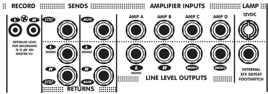
These unbalanced RCA outputs are pre-EQ(), pre-SPEAKER PROCESSOR and post-faders (L&R), as well as post-effects.
The RECORD output signal consists of the L&R level (including effects) from the L&R masters. The signal is pre-graphic-EQ and speaker processor. This way, you can EQ the speaker system without those EQ adjustments being present on the RECORD output signals. As the panel artwork indicates, optimum level for recording is 0dB (average) on the VU-METERS. For more information on setting gain levels for 0dB, see under SOLO Button.
EFX2 & AUX SEND Jacks
These carry the dry, mono output of the EFX2 and AUX summing stages and are regulated by their SEND masters (and are TRS balanced).
As a rule, you would connect either or both of these outputs to the inputs of effects processors. Alternately, either may be used as an audio output, perhaps to another PA system, recording (mono) or broadcast mixer. Just remember that the channel EFX2 and AUX send controls are post-fader, in other words their send signal levels are affected by the channel faders.
The EFX2 and AUX SEND jack signals are dry; i.e. they are not affected by the L/R graphic-EQ and have no internal effects. They are balanced connectors, but will work with either balanced or unbalanced cables. However, for optimum quiet performance, use balanced patch cords whenever possible
MON1, MON2, EFX1, EFX2 & AUX SEND Masters, SOLOs and CLIP LEDs
Each master regulates the output levels of its gain stage. Each stage also has a CLIP LED and, with the exception of the EFX1 & 2 and AUX buses, a SOLO button and LED. Output signals are available at the applicable SEND jacks except for EFX1, which is internally routed to the input of built-in effects processor.
Adjust these sends for maximum level at the input of the connected (or internal) units without clipping. If clipping is indicated on a SEND LED, reduce that master's level. The same action should be taken if clipping is indicated on the input of anything connected to the SEND jacks or on the EFX1 RETURN LEVELS channel.
The SOLO functions permit you to listen (to each MASTER send) through headphones. The LED indicates that the signal is being summed into the solo (AFL & PFL busses). Remember to turn SOLOs off when you are through listening to them.
EFX2 & AUX RETURN Jacks
These are the inputs to the EFX2 and AUX RETURN master sections. The L / MONO RETURN jacks are patched internally to the R RETURN jacks which are switching jacks that interrupt the patch when a jack is inserted. Both returns are TRS balanced.
The output/s of mono or stereo effects units would be connected here. If an effects unit is mono, plug its output into the L/MONO jack. If it is stereo, use both jacks. Signals coming into the EFX2 and/or AUX RETURN jacks are routed to the EFX2 and AUX RETURN masters so that their mix levels to both MON1 and MON2 channels and the L/R main PA channel can be regulated precisely.
These jacks may alternately be used to connect another audio source, e.g. a CD-player, tape deck, instrument amp line out, keyboard or another mixer. The EFX2 and AUX RETURN masters would regulate their mix levels to the main and monitor systems. The EFX2 and AUX RETURN jacks are balanced, but will work with either balanced or unbalanced cables. However, for optimum, quiet performance, use balanced patch cords whenever possible.
RETURN Levels Masters, SOLOs & CLIP LEDs
EFX1 is the internal effects processor bus. The EFX1 RETURN masters are between its output and the internal inputs to the MON1, MON2 and L/R (main) buses. The EFX2 and AUX RETURN masters are between their respective RETURN jacks and the internal inputs to the MON1, MON2 and L/R (main) buses. SOLOs can be PFL or AFL as per the SOLO MODE button setting. In mono effects mode EFX2 gets signal from internal-EFX2.
These MASTERS permit mixing internal and/or external effects or other input signals to the MON1 and MON2 monitor channels and the L/R main channel. The SOLO buttons let you preview through headphones whatever signals are coming into each RETURN LEVELS channel before turning up these masters (SOLO MODE button set for PFL) or after they are turned up (SOLO MODE at AFL). The SOLO LED stays on to indicate that SOLO is active. Remember to depress the button again when you are finished soloing.
AUX CLIP & EFX2 CLIP/ DEFEAT indicate excessive signal levels coming in via the AUX RETURN. This can mean that the EFX2 SEND fader or the AUX MASTER SEND levels are set too high causing the effects units to put out too much signal. Turn them down. Trying to reduce clipping at this stage by turning down the RETURN LEVELS masters will not work.
Clipping is more likely to happen when a high-output audio source, possibly another mixer or an instrument amp's line output, has been connected to one or both of the RETURN jacks. In this case lower that mixer's (or whatever's) master level or other volume controls until the CLIP LED goes out. Again, do not try to remedy the problem by turning down the RETURN levels.

Master Sends Section
MON1 & MON2 SEND Masters, CLIP LEDs & SOLO Buttons
Each master, CLIP LED and SOLO is between the summed channel send signals and its designated EQ and SEND jack. The SOLOs and the CLIP LEDs are post-master. Once again, the main L/R bus is on SOLO when all the other solos are off.
The CLIP LEDs indicate near-overload conditions. Reduce the appropriate master MON SEND setting or the channel MON send settings to avoid distortion.
Because the monitor bus SOLO is post-master, you hear the final mix through headphones with the SOLO MODE in either AFL or PFL. Final monitor mix levels will therefore appear on the VU-METER in either AFL or PFL.
AUX SEND Master and CLIP LED
The AUX SEND master is an attenuator between the summed channel AUX sends and the AUX SEND jack. The CLIP LED is post-master.
If the AUX CLIP LED becomes active, reduce the AUX SEND master setting or the channel AUX send levels to reduce the risk of distortion. Otherwise, set the AUX master as required for the application - high enough to deliver ample signal strength but not too high for the connected unit's input headroom (check the unit's input clip indicator).
EFX1 and EFX2 SEND MASTERS and CLIP LEDs
These faders are between the channel EFX sends and either the internal effects processor (EFX1) or the EFX2 SEND jack (EFX2). The CLIP LEDs are post-fader.
See under Input Channel Features - EFX1 & 2 SENDS for tips about setting up effects.
EFX System Masters, EFX MODE Button & LEDs
The onboard effects processor has two operating MODEs: 1) MONO with the processor acting as two independant mono units, one for each EFX bus and each with its own 16-preset selector. 2) STEREO in which case the processing is in stereo and the two controls, EFFECT on the left and MODIFY on the right, provide a total of 255 presets.
You may run a full stereo main PA whether the EFX MODE button is set for STEREO or MONO. The only difference will be whether or not the effect itself is stereo. In MONO MODE, for example, you can add two effects - eg.reverb and echo or a special effect and reverb. In STEREO MODE, certain reverb effects are enhanced by stereo separation and you get a larger selection.
Two menus of presets appear on the control panel above and below the EFX masters. The split menu above the controls is for MONO operation, and the one below is for STEREO (EFX1 only). To preview effects in MONO MODE (EFX1 & EFX2), apply signal to one of the input channels, turn both EFX send controls up to 5 and push the channel fader up 1/2-way or better. Push up the EFX1 & 2 send faders 1/2-way and set the L&R to faders to 5. Use the EFX MODE button, select MONO or STEREO as per the LED then set the SOLO MODE for PFL. Now plug in headphones, turn up the
HEADPHONES level until you hear the effects. Finally, experiment with the EFX select masters, and after choosing the desired effect then turn up the EFX1&2 RETURNS.
Internal EFX Defeat Footswitch Jack
This regulates internal EFX, EFX1 and 2 in mono or EFX1 in stereo. Connect a standard footswitch here (e.g. our model IFS-1A) to switch the internal effects on and off.
L & R (Main) MASTER SEND Faders and CLIP LEDs
The left & right main summing bus receives signals directly from the channel faders, as well as the three L&R RETURN LEVELS controls. CLIP LEDs fire a few dB lower from actual clipping so some activity is allowable. Signal routing goes from the master faders (to STEREO EQ)... and to the SPEAKER PROCESSOR. Then, to both the L&R LINE LEVEL OUTPUTS and the normally closed switching lugs on the AMP A&B INPUT jacks – thereafter to amps A&B. (At the same time, the post-master signal goes directly to the RECORD outputs, bypassing the EQ, processor, etc.)
The CLIP LEDs are unlikely to fire as this stage of the mixer has a large amount of headroom. However, if one, or both LEDs become very active (small amounts of activity are OK), check the RETURN LEVELS CLIP LEDs and reduce the settings of any L&R RETURN master/s in channels showing clipping.
The L&R masters regulate the level of the main stereo mix available at the RECORD outputs (no main EQ), and the L&R LINE LEVEL OUTPUTS. They also regulate the amplifier A&B power output levels (unless another mixer has been patched into the AMP A&B INPUTS in which case its masters will determine power output).
Speaker Processor Curve and ENABLE Buttons
The POWERMAX features a choice of two low-frequency boost curves centred at 50Hz and 80Hz and selectable via the CURVE button. The 50Hz curve has a high Q factor for subwoofoers while the 80Hz curve is slightly broader and better suited for full range cabinets. An ENABLE, ON-OFF button is also provided.
It is advisable to use this feature judiciously. For example you would probably not want to boost the main L/R EQ's low frequencies while it is enabled. On the other hand, it can add valuable depth to the speaker system. Experiment with it during a sound check. In case of low-frequency feedback, simply put the ENABLE button to the OFF position.
L/R Main EQ
This is a stereo 9-band EQ on the output of the main bus. Range is +/-12dB with centers at one-octave intervals from 63Hz to 16kHz.
The main EQ would most often be set during a sound check and used to carefully adjust main speaker response (no radical boosts). It is also useful for curbing feedback tendencies, but remember that monitors most often cause your feedback problems. Naturally, monitor feedback comes out the main PA too which, when you are out front at the mixer station, leads to the illusion that the main system needs EQing. See under MON1 and MON2 EQ's for more about this.
When setting the main EQ, do not automatically go to a smiling curve as with a home stereo - which will cost your system both headroom and gain before feedback. Initially, keep the EQ curve as close to flat (all sliders at center) as possible, then make necessary adjustments as required during the sound check to cut feedback frequencies.
MON1 & MON2 EQs
These are 9-band mono EQ's with + / - 12dB on the same centers as the L/R MAIN EQ. They are inserted between the monitor buses and the # 3 & 4 power amps, also the MON1 & 2 LINE LEVEL OUTPUTS.
These EQ's should be set flat (all sliders at center) then adjusted for minimal monitor feedback during a sound check. If feedback does set in during the job, you will be tempted to blame the mains because that's what you hear from the mixing station out front. Don't be misled. As a rule it's one or more of the monitors, but of course the noise comes out the mains too. Use your channel MUTE buttons to mute each channel briefly and see if the noise stops. You may also use the CLIP LEDs to hunt for feedback channels. If the channel GAINs are set high enough per instructions, feedback channels will have increased CLIP light


activity. If only one or two channels are causing feedback, the best solution is to adjust the channel EQ or, better still, connect monitor-feedback-prone mics to the channels with OVERLOAD PROTECTION. If, on the other hand, a larger percentage of the monitors are having feedback problems, use one or both of the MON EQs to cut monitor level at the feedback frequencies.
VU-Meter, SOLO MODE Button, AFL & PFL LEDs
The VU-METER reflects either the post-EQ, post-SPEAKER PROCESSOR main bus output levels, or the SOLO bus levels. Flashing of the yellow LEDs at +2 and +4 should coincide with flashing of the AMP A and/or AMP B AMPLIFIER FULL POWER LEDs. The red +7 and +10 LEDs indicate that the main mixing bus is overloaded.
The SOLO MODE button allows you to switch between AFL and PFL. AFL mode allows you to view post fader levels in the channels, effects to L&R in the EFX returns, and the MON1 / MON2 mix levels. PFL mode allows you to view pre-fader levels in the channels (even muted channels), effects input in the EFX returns, and the MON1 / MON2 mix.
- The AFL and PFL LEDs indicate which solo mode is currently in effect.
To view the main system levels, release all the SOLO buttons so that neither the PFL nor the AFL LED flashes. To check SOLO levels, press for PFL. Occasional peaks between +7 and +10 will not reflect actual clipping, however if such peaking becomes continuous, reduce either the channel fader levels if you are in AFL mode (or the input level of the SOLO source if you are in PFL). - Look for the illuminated SOLO LED and turn that master down.
HEADPHONES Level Control and Output Jack
The level control regulates the output of the headphone amplifier. The headphone output jack is located on the front of the mixer beside the PHANTOM POWER button. The headphone program originates from the main L/R bus unless a solo is active in which case it originates from the SOLO bus.
Amplifier AMP A, B, C & D Inputs
Each AMPLIFIER INPUT uses a switching jack that cuts off internal signals routed to the power amp when a jack is inserted.
The AMPLIFIER INPUT's have a few possible uses. For example, they enable you to access, and isolate the main power built-in amps so that they may be used in conjunction with an electronic crossover. (Used to bi-amp subwooers and full-range speakers.) In this case you would patch as follows... 1) POWERMAX L / MONO LINE LEVEL OUTPUT to the crossover's input (if it is a stereo crossover, pick one channel and use its input). 2) From the crossover's low -frequency, or

subwoofer output to the POWERMAX AMP A INPUT. 3) From the crossover's high frequency output to AMP B INPUT. 4) Now, connect the subwoofer to the AMP A SPEAKER output/s and the full-range cabinets to the AMP B SPEAKER output/s.
Two 8-Ohm full-range speakers, and two 8-Ohm subwoofer can be powered this way. Actually, if you have a 3-way crossover or processor and only need one monitor power amp, you can tri-amp by using AMP A for subs, AMP B for woofers and AMP D for horns and/or tweeters.
Alternatively, the AMPLIFIER INPUTS can be used to slave one or more of the power amps - perhaps if the mixer is connected to a rack of amps and now the built-in amps are free to be used for other things. In another case, you might be using the POWERMAX L&R LINE LEVEL OUTPUTS, also MON1 & 2, patched into four of another mixer's input channels. Now you may want to amplify the full mix coming out of that other board including whatever it's doing (possibly you're jamming with another group and you need extra channels). You would simply patch its main and monitor outputs into the appropriate AMPLIFIER INPUTS and now the two mixers are linked and the POWERMAX amps are ready to power up main and monitor speakers.
Amplifier Full Power LEDs
The AMPLIFIER FULL POWER LEDs are located in the upper right panel area just above the main EQ. They indicate that one or more power amp limiters (all non-defeatable) are working. The more FULL POWER LED activity, the more limiting. Limiting begins 10dB down from the onset of clipping and tends to be sonically transparent unless these LEDs are working constantly.
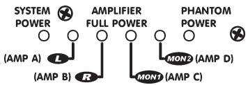
Given the amount of available power, it is unlikely that you will be pushing the system hard enough to run completely out of power amp headroom. If that does happen however, built-in limiting will ensure that no clipped signals endanger your speakers. If the AMPLIFIER FULL POWER LED is on continuously for any particular amp, reduce the master for that amp. Occasional flashing simply means that the limiter is reacting to peaks and requires no action on your part.
Speaker Connections
SpeakonTM and 1/4-inch speaker outputs are located on the back panel and are identified as LEFT (A), RIGHT (B), MON1 (C) and MON2 (D). All connectors, for a given amp, are wired in parallel. The minimum impedance of 4-ohms per amp is for full power. Loads below 4-ohms will be tolerated, but will cause reductions in output power.
You may connect one or two 8-ohm speakers or one 4-ohm speaker to each amplifier. It is possible to connect more than this, but output power will be reduced to levels which are safe for the output transistors.
LAMP Connector
Connects a 12VDC gooseneck lamp with a BNC connector (e.g. Yorkville model GNL600). - max current 500mA
System Power LED
Located to the left of the AMPLIFIER FULL POWER LEDs, this is the AC pilot light.
POWER Switch and Circuit Breaker
These are located on the back of the mixer by the SPEAKER connections. The breaker is rated 15 amps (8 amps for export models)
Basic Operating Instructions
Note A: For in-depth coverage of specific features, hookups, etc., look under the appropriate feature heading in the main body of the manual.
- Connect the power cord to a grounded AC outlet.
- Connect mics and line-level sources to the mono channels, tape decks or CD players to the Stereo channels. Do not connect a phono turntable without using a phono preamp.
- Set all channel levels and masters at "0" (for now).
Note B: The following should all be done during a sound check
- With signals coming into the channels and faders off, press SOLO and adjust the channel GAIN controls for 0dB on the VU-METER (PFL).
- Connect any external effects to the EFX2 SEND and RETURN jacks and/or the AUX SEND and RETURN jacks. Now set the desired SEND and RETURN masters at halfway.
- Set channel EQs, main and monitor graphic EQs flat (at center). If unsure of Mid-Sweep, sat at 2.5kHz
- Turn up the desired channels' EFX1 and/or EFX2 and/or AUX sends halfway.
- Connect main and monitor speakers to their designated outputs on the back panel (2 x 8-ohms or 1 x 4-ohms per amp).
- Gradually bring up the channel fader levels to achieve the desired channel mix though the main PA. Set the MASTERSfor overall level.
- Bring the main L&R faders up to the "0" reference setting and turn the MON1 and/or 2 MASTER SENS up to 5. Set the Channel/s to "0."
- Adjust channel EFX sends and masters as required for the desired effects mix through the main system.
- Per instructions from the stage, adjust the MON1 and/or MON2 channel sends and the MON1 and/or MON2 EFX1 or 2 RETURN LEVELS.
- Adjust the L&R, MON1 & 2 EQ's as needed. See under the feature headings for more details.

North American Models
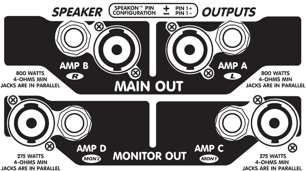
Export Models
SPECIFICATIONS
Frequency Response
T.H.D. (L&R Out with -10dB input)
Input Referred Noise (to Line Out)
Phantom Power
Max. Gain to Line Out (Mic input)
Digital Signal Processor Effects
Primary Graphic Equalizer
Secondary Graphic Equalizer
EQ (mono channels)
EQ (stereo channels)
Effects Sends / Monitor Sends
Channel Inserts
COP (Channel Overload Protection)
Balanced XLR Channel Inputs
Balanced 1/4-inch Channel Inputs
Unbalanced RCA Channel Inputs
Hum Cancelling Line Level Outputs
Hum Cancelling Line Level Inputs
Main Amp Outputs
Monitor Amp Outputs
(Tone and graphic EQ flat) +/- 2dB, 20Hz - 20KHz
0.03%
-119 dBv @ 150 ohms
48 volts
+72 dB (Mic Input) + 56 dB (Line Input)
Dual Mode, 16 bits, 255 sounds total
9-Band (stereo) 63Hz to 16kHz
2x9-Band (mono) 63Hz to 16kHz
LOW, MID-SWEEP, & HIGH
LOW, LOW MID, MID & HI
3 post-fade, 2 pre-fade
ch.7-12 (PM16), ch. 13-18 (PM22)
ch. 1-6 (PM16), ch. 1-12 (PM
ch. 1-12 (PM16), ch. 1-18 (PM22)
ch. 1-16 (PM16), ch. 1-22 (PM22)
ch. 13-16 (PM16), ch. 19-22 (PM22)
L&R, Mon1, Mon2 (all ¼-inch TRS) (EFX2) (AUX)
Amp A, B, C, & D (1/4-inch TRS)
Amp A and B: 2 x 1/4 -inch and Speakon™
Amp A and B: 1/4 -inch and Speakon™ (export)
Amp C and D: 2 × 1/4 -inch
Amp C and D: 1/4 -inch and Speakon™ (export)
AMPLIFIER SPECIFICATIONS
Power Output (0.1% THD 1kHz)
THD (Total Harmonic Distortion)
Hum and Noise
Input Sensitivity
Amplifier Gain
Input Impedance
Protection
Cooling
Transformer Type
MAIN
MON
MAIN 4-ohms
MON 4-ohms
800W 8
275W 8-ohms
1kHz<0.04%
20Hz - 20KHz <0.1%
1kHz<0.004%
20Hz - 20KHz < 0.04%
MAIN -106dB
1.4 VRMS for full output
MON 24dB
20KOhms Balanced 10Kohms Unbalanced
Thermal / Load / DC (2)
2 Variable speed DC fans
Toroidal
FEATURES
Master EQ / Monitor 1 EQ / Monitor 2 EQ
Headphone Monitor Features
Internal Effects Footswitch
Full-Power Indicator (amplifier)
12VDC Little-Lite™ Connector
VU-Meter
Solo Switches, Activity/Solo LEDs
Mute Switches, Clip/Mute LEDs
Hi-Pass Filter Switches
Yes/Yes/Yes
Level AFL/PFL Switch, 1 / 4 -inch TRS Output
Yes
Yes (total 4)
Yes (BNC)
2 x 12 LEDs Average / Floating peak
All Channels, Mon1, Mon2, and Effects Returns
All Channels
ch. 1-12 (PM16), ch. 1-18 (PM22)
POWER REQUIREMENTS
Mixer & Power Amplifier
Weight
< 1440 watts avg
PM16: 68 lb (30.8 Kg)
PM22:71 Ib (32.2 Kg)
Voltage AC
Shape
Test LOAD
120 VRMS, 60Hz. 230
Sinusoid
0.1% high power laboratory load,
temperature stable.
Specifications and power ratings are measured with an AC line controlled under load to within 1% on all parameters.
ADDENDUM EQ SWEEP Control
Although frequency sweep controls have graced the channel-EQs of recording mixers for many years, they are only found on the more upscale PA mixers. As a result many PA users, even veterans, are unfamiliar with their function. The SWEEP control determines what range of frequencies is affected by the MID cut/boost. It moves or sweeps the MID control's peak or notch in response all the way up to several thousand Hertz or down to below 100Hz. As a result it can have quite a noticeable effect on the sound especially since the MID cut or boost will be interacting with whatever cuts or boosts you may have set with the LOW or HIGH EQ controls.
For example, if you have set a LOW boost, a MID boost swept all the way down to the lowest frequency setting will alter the sound of lows AND increase their volume. Be careful this doesn't damage your woofers. And watch out for your tweeters/horns if you sweep the boost up to the higher settings while the HI EQ is boosted.
Considering that the SWEEP control can alter everything you are accustomed to an EQ doing, it would be worthwhile to spend some time becoming acquainted with how it works. As music plays through a channel on the mixer and speakers, adjust that channel's MID, first for a boost then for a cut and SWEEP them back and forth. (If there is no MID cut or boost setting, i.e. if it is set at the centre position, the SWEEP will have no effect at all). Now repeat the process with that channel's LOW and HIGH EQ controls at various settings (but with the volume at a safe level for the speakers).
Hint: The PowerMAX SWEEP has a "home base" setting marked with a triangle at the 2.5kHz mark. This approximately corresponds to the setting of the fixed mid controls on our other mixers. Set channels not requiring SWEEP equalization at 2.5kHz and the MID cuts or boosts will have more standard results.
Together, MID and SWEEP controls can be used to accomplish a variety of tasks from combatting feedback to improving the way things sound through the PA or on recording. Here are some of those tasks & settings:
Note: These are approximate settings only. Use them as a starting point and "tune around" them.
Killing feedback? Set MID at -6dB and slowly rotate SWEEP until the feedback stops. If needed cut the MID further.
Bonky sounding snare drum? -6dB @ 200Hz (roll off LOW EQ -6dB)
Boomy bass drum? -6dB @ 300Hz (LOW EQ @ +6dB & HIGH EQ @ +3dB)
Fwashy sounding cymbals? -9dB @ 300Hz (roll off LOW EQ -15dB)
Excessive hiss from guitar, bass or keyboard amp? +3dB @ 5kHz (HI EQ rolled off -9dB)
Fading vocal range (notes too low for singer)? +3dB @ 80Hz (LOW EQ rolled off -6dB)
Puffing on harmonica mic? -9dB @ 80Hz (LOW EQ rolled off -12dB)
Rack Toms? -3dB @400 Hz
Floor tom? -6dB @ 200Hz
Generally speaking, you will probably end up with the MID in cut mode for most problem solving uses of the SWEEP control. In any case you will learn to use this feature judiciously. The best PA EQ setting is the one with the least adjustment, but when you need to solve a problem it's good to know how to use the tools.
Introduction
North American Models
SPEAKER
4-OPMIS MIN JACKS ARE IN PARALLEL

MAIN OUT


AMP D
MON2
MONITOR OUT
AMP C
MON1
275 WATTS
4-OHMS MIN
JACKS ARE IN PARALLEL
Export Models
SPEAKER
Mode double, 16 bits, 255 effects total
MAIN -106dB MON -108dB
can. 1-412 (PM16), can. 1-18 (PM22)
PUISSANCE REQUIRE
Toms; - 3dB @ 400@@Hz
Floor tom; - 6dB @ 200Hz
1 0.5s Bright Small Room
2 0.5s Warm Small Room
3 0.5s Dark Small Room
4 0.8s Bright Small Room
5 0.8s Warm Small Room
6 1.0s Bright Small Room
7 1.0s Warm Small Room
8 1.2s Bright Medium Room
9 1.2s Warm Medium Room
10 1.5s Bright Medium Room
11 1.5s Warm Medium Room
12 1.5s Dark Medium Room
13 2.0s Bright Large Room
14 2.0s Warm Large Room
15 2.5s Bright Large Room
16 2.5s Warm Large Room
ROOMS & THICKENING DELAYS
HALLS & THICKENING DELAYS
1 1.5s Dark Medium Hall
2 1.5s Warm Medium Hall
3 1.5s Bright Medium Hall
4 2.0s Dark Medium Hall
5 2.0s Warm Medium Hall
6 2.0s Bright Medium Hall
7 2.5s Dark Medium Hall
8 2.5s Warm Medium Hall
9 2.5s Bright Medium Hall
10 3.5s Dark Medium Hall
11 3.5s Warm Medium Hall
12 3.5s Bright Medium Hall
13 5.0s Dark Large Hall
14 5.0s Warm Large Hall
15 8.0s Dark Huge Hall
16 8.0s Warm Huge Hall
J CHAMBERS/PLATES + THICKENING DELAYS
N LONG DELAYS 1.200 mper hour delay
0.8s Warm Chamber
0.8s Bright Chamber
1.2s Warm Chamber
1.2s Bright Chamber
1.5s Warm Chamber
1.5s Bright Chamber
2.5s Warm Chamber
2.5s Bright Chamber
3.5s Warm Chamber
3.5s Bright Chamber
0.3s Bright Plate
0.5s Bright Plate
0.8s Bright Plate
1.2s Bright Plate
1.5s Bright Plate
2.0s Bright Plate
1 200ms low regen delay
2 200ms medium regen delay
3 225ms low regen delay
4 225ms medium regen delay
5 250ms low regen delay
6 250ms medium regen delay
7 275ms low regen delay
8 275ms medium regen delay
9 300ms low regen delay
10 300ms medium regen delay
11 325ms low regen delay
12 325ms medium regen delay
13 350ms low regen delay
14 350ms medium regen delay
15 375ms low regen delay
16 375ms medium regen delay
1 200ms low regen delay
2 200ms medium regen delay
3 225ms low regen delay
4 225ms medium regen delay
5 250ms low regen delay
6 250ms medium regen delay
7 275ms low regen delay
8 275ms medium regen delay
9 300ms low regen delay
10 300ms medium regen delay
11 325ms low regen delay
12 325ms medium regen delay
13 350ms low regen delay
14 350ms medium regen delay
15 375ms low regen delay
16 375ms medium regen delay
1 0.5s Bright Small Room + 50ms doubling delay
2 0.5s Warm Small Room + 40ms doubling delay
3 0.5s Dark Small Room + 40ms doubling delay
4 0.8s Bright Small Room + 60ms doubling delay
5 0.8s Warm Small Room + 50ms doubling delay
6 1.0s Bright Small Room + 70ms slap delay
7 1.0s Warm Small Room + 50ms doubling delay
8 1.2s Bright Medium Room + 50ms doubling delay
9 1.2s Warm Medium Room + 50ms doubling delay
10 1.5s Bright Medium Room + 80ms slap delay
11 1.5s Warm Medium Room + 60ms doubling delay
12 1.5s Dark Medium Room + 70ms slap delay
13 2.0s Bright Large Room + 80ms slap delay
14 2.0s Warm Large Room + 60ms doubling delay
15 2.5s Bright Large Room + 100ms slap delay
16 2.5s Warm Large Room + 80ms slap delay
ROOMS & REGENERATION DELAYS
1 1.5s Dark Medium Hall + 50ms doubling delay
2 1.5s Warm Medium Hall + 70ms slap delay
3 1.5s Bright Medium Hall + 90ms slap delay
4 2.0s Dark Medium Hall + 90ms slap delay
5 2.0s Warm Medium Hall + 70ms slap delay
6 2.0s Bright Medium Hall + 50ms doubling delay
7 2.5s Dark Medium Hall + 70ms slap delay
8 2.5s Warm Medium Hall + 80ms slap delay
9 2.5s Bright Medium Hall + 100ms slap delay
10 3.5s Dark Medium Hall + 80ms slap delay
11 3.5s Warm Medium Hall + 90ms slap delay
12 3.5s Bright Medium Hall + 100ms slap delay
13 5.0s Dark Large Hall + 80ms slap delay
14 5.0s Bright Large Hall + 100ms slap delay
15 8.0s Dark Huge Hall + 100ms slap delay
16 8.0s Warm Huge Hall + 100ms slap delay
1 0.5s Bright Small Room + 200ms regen delay 2 0.5s Warm Small Room + 175ms regen delay
1 0.5s Bright Small Room +200ms regen delay
2 0.5s Warm Small Room +175ms regen delay
3 0.5s Dark Small Room +150ms regen delay
4 0.8s Bright Small Room +200ms regen delay
5 0.8s Warm Small Room +150ms regen delay
6 1.0s Bright Small Room +175ms regen delay
7 1.0s Warm Small Room +125ms regen delay
8 1.2s Bright Medium Room +150ms regen delay
9 1.2s Warm Medium Room +200ms regen delay
10 1.5s Bright Medium Room +200ms regen delay
11 1.5s Warm Medium Room +175ms regen delay
12 1.5s Dark Medium Room +150ms regen delay
13 2.0s Bright Large Room +200ms regen delay
14 2.0s Warm Large Room +125ms regen delay
15 2.5s Bright Large Room +150ms regen delay
16 2.5s Bright Large Room +200ms regen delay
D ROOMS/HALLS &CHORUS
H GATED/REVERSE REVERB
1 1.5s Dark Medium Hall + 150ms regen delay
2 1.5s Warm Medium Hall + 175ms regen delay
3 1.5s Bright Medium Hall + 200ms regen delay
4 2.0s Dark Medium Hall + 200ms regen delay
5 2.0s Warm Medium Hall + 150ms regen delay
6 2.0s Bright Medium Hall + 175ms regen delay
7 2.5s Dark Medium Hall + 200ms regen delay
8 2.5s Warm Medium Hall + 150ms regen delay
9 2.5s Bright Medium Hall + 175ms regen delay
10 3.5s Dark Medium Hall + 125ms regen delay
11 3.5s Dark Medium Hall + 150ms regen delay
12 3.5s Bright Medium Hall + 200ms regen delay
13 5.0s Dark Large Hall + 175ms regen delay
14 5.0s Bright Large Hall + 200ms regen delay
15 8.0s Dark Large Hall + 150ms regen delay
16 8.0s Bright Large Hall + 200ms regen delay
1 0.5s Bright Room + slow chorus 1 0.8s decay 100ms Gate 2 35ms slap delay 2 Pitch Shift octave up 2 Pitch Shift major 2nd up
SHORT DELAYS 1 30ms slap delay 2 35ms slap delay
1 0.8s Warm Chamber + 150ms regen delay
2 0.8s Bright Chamber + 125ms regen delay
3 1.2s Warm Chamber + 175ms regen delay
4 1.2s Bright Chamber + 200ms regen delay
5 1.5s Warm Chamber + 150ms regen delay
6 1.5s Bright Chamber + 200ms regen delay
7 2.5s Warm Chamber + 175ms regen delay
8 2.5s Bright Chamber + 125ms regen delay
9 3.5s Warm Chamber + 200ms regen delay
10 3.5s Bright Chamber + 150ms regen delay
11 0.3s Bright Plate + 125ms regen delay
12 0.5s Bright Plate + 150ms regen delay
13 0.8s Bright Plate + 200ms regen delay
14 1.2s Bright Plate + 175ms regen delay
15 1.5s Bright Plate + 150ms regen delay
16 2.0s Bright Plate + 200ms regen delay
SHORT DELAYS 1 30ms slap delay 2 35ms slap delay
K CHAMBERS/PLATES
0.8s Warm Chamber + 50ms doubling delay
0.8s Bright Chamber + 50ms doubling delay
1.2s Warm Chamber + 60ms doubling delay
1.2s Bright Chamber + 70ms slap delay
1.5s Warm Chamber + 70ms slap delay
1.5s Bright Chamber + 80ms slap delay
2.5s Warm Chamber + 80ms slap delay
2.5s Bright Chamber + 100ms slap delay
3.5s Warm Chamber + 90ms slap delay
3.5s Bright Chamber + 100ms slap delay
0.3s Bright Plate + 40ms doubling delay
0.5s Bright Plate + 50ms doubling delay
0.8s Bright Plate + 50ms doubling delay
1.2s Bright Plate + 80ms slap delay
1.5s Bright Plate + 80ms slap delay
2.0s Bright Plate + 100ms slap delay
1 0.8s Warm Chamber + 50ms doubling delay
2 0.8s Bright Chamber + 50ms doubling delay
3 1.2s Warm Chamber + 60ms doubling delay
4 1.2s Bright Chamber + 70ms slap delay
5 1.5s Warm Chamber + 70ms slap delay
6 1.5s Bright Chamber + 80ms slap delay
7 2.5s Warm Chamber + 80ms slap delay
8 2.5s Bright Chamber + 100ms slap delay
9 3.5s Warm Chamber + 90ms slap delay
10 3.5s Bright Chamber + 100ms slap delay
11 0.3s Bright Plate + 40ms doubling delay
12 0.5s Bright Plate + 50ms doubling delay
13 0.8s Bright Plate + 50ms doubling delay
14 1.2s Bright Plate + 80ms slap delay
15 1.5s Bright Plate + 80ms slap delay
16 2.0s Bright Plate + 100ms slap delay
P SPECIAL EFFECTS
1 50ms doubling delay + slow chorus
2 80ms slap delay + medium chorus
3 100ms slap delay + medium chorus
4 150ms regen delay + slow chorus
5 175ms regen delay + medium chorus
6 200ms regen delay + slow chorus
7 225ms regen delay + medium chorus
8 250ms regen delay + slow chorus
9 275ms regen delay + medium chorus
10 300ms regen delay + slow chorus
11 325ms regen delay + medium chorus
12 350ms regen delay + slow chorus
13 370ms regen delay + medium chorus
14 380ms regen delay + slow chorus
15 390ms regen delay + medium chorus
16 400ms regen delay + slow chorus
DO DELAYS & CHORUS
1 390ms low regen delay
2 390ms medium regen delay
3 400ms low regen delay
4 400ms medium regen delay
5 410ms low regen delay
6 410ms medium regen delay
7 420ms low regen delay
8 420ms medium regen delay
9 430ms low regen delay
10 430ms medium regen delay
11 450ms low regen delay
12 450ms medium regen delay
13 475ms low regen delay
14 475ms medium regen delay
15 500ms low regen delay
16 500ms medium regen delay
N LONG DELAYS
M MEDIUM DELAYS
EFX1 EFX2
ROOMREVERBS
A 0.8s Warm Small Room 1
B 1.2s Warm Room 2
C 1.5s Bright Medium Room 3
HALL REVERBS
D 2.0s Bright Medium Hall 4
E 3.0s Warm Hall 5
F 3.5s Bright Medium Hall 6
PLATE REVERBS
G 0.8s Bright Plate 7 H 2.5s Warm Chamber 8*
DELAYS
1 100ms slap delay 9
J 150ms medium regen delay 10
K 200ms regen delay 11
L 250ms low regen delay 12
M 300ms medium regen delay 13
N 350ms regen delay 14
SPECIAL EFFECTS
O Chorus 15
P Flanger 16

- a simultaneous setting of "H" on GFX1 and "8" on GFX2 results in the GFX2 preset to become "0.8s Bright Plate"
Unlimited Warranty
Yorkville's two and ten-year unlimited warranty on this product is transferable and does not require registration with Yorkville Sound or your dealer. If this product should fail for any reason within two years of the original purchase date (ten years for the wooden enclosure), simply return it to your Yorkville dealer with original proof of purchase and it will be repaired free of charge. This includes all Yorkville products, except for the YSM Series studio monitors, Coliseum Mini Series and TX Series Loudspeakers.
Freight charges, consequential damages, weather damage, damage as a result of improper installation, damages due to exposure to extreme humidity, accident or natural disaster are excluded under the terms of this warranty. Warranty does not cover consumables such as vacuum tubes or par bulbs. See your Yorkville dealer for more details. Warranty valid only in Canada and the United States.
Garantie Illimitée
Niagara Falls, New York
14305 USA
Voice: (716) 297-2920
Fax: (716) 297-3689



- OWNER'S MANUAL
- Power Sources
- Hazards
- Power Cord
- Service
- SUIVEZ TOUTES LES INSTRUCTIONS
- Input Channel Features
- Input Overload Protection
- INSERT Jacks
- MIC Inputs
- PHANTOM POWER Switch and LED
- BAL LINE Inputs
- CD/TAPE Inputs (Stereo Channels Only)
- HPF Button
- GAIN Control
- Channel EQ
- MON1 & MON2 Sends
- AUX Send
- EFX1 & 2 Sends
- PAN Control (Mono Channels)
- BALance Control (Stereo Channels)
- CLIP/MUTE Light
- MUTE Button
- Solo Active LED
- SOLO Button
- LEVEL Fader
- Master Section
- RECORD Outputs
- EFX2 & AUX SEND Jacks
- MON1, MON2, EFX1, EFX2 & AUX SEND Masters, SOLOs and CLIP LEDs
- EFX2 & AUX RETURN Jacks
- RETURN Levels Masters, SOLOs & CLIP LEDs
- Master Sends Section
- MON1 & MON2 SEND Masters, CLIP LEDs & SOLO Buttons
- AUX SEND Master and CLIP LED
- EFX1 and EFX2 SEND MASTERS and CLIP LEDs
- EFX System Masters, EFX MODE Button & LEDs
- Internal EFX Defeat Footswitch Jack
- L & R (Main) MASTER SEND Faders and CLIP LEDs
- Speaker Processor Curve and ENABLE Buttons
- L/R Main EQ
- MON1 & MON2 EQs
- VU-Meter, SOLO MODE Button, AFL & PFL LEDs
- HEADPHONES Level Control and Output Jack
- Amplifier AMP A, B, C & D Inputs
- Amplifier Full Power LEDs
- Speaker Connections
- LAMP Connector
- System Power LED
- POWER Switch and Circuit Breaker
- Basic Operating Instructions
- Note B: The following should all be done during a sound check
- SPECIFICATIONS
- AMPLIFIER SPECIFICATIONS
- FEATURES
- POWER REQUIREMENTS
- ADDENDUM EQ SWEEP Control
- Introduction
- North American Models
- Export Models
- PUISSANCE REQUIRE
- ROOMS & THICKENING DELAYS
- HALLS & THICKENING DELAYS
- J CHAMBERS/PLATES + THICKENING DELAYS
- N LONG DELAYS 1.200 mper hour delay
- ROOMS & REGENERATION DELAYS
- 0.5s Bright Small Room + 200ms regen delay 2 0.5s Warm Small Room + 175ms regen delay
- D ROOMS/HALLS &CHORUS
- H GATED/REVERSE REVERB
- 0.5s Bright Room + slow chorus 1 0.8s decay 100ms Gate 2 35ms slap delay 2 Pitch Shift octave up 2 Pitch Shift major 2nd up
- SHORT DELAYS 1 30ms slap delay 2 35ms slap delay
- K CHAMBERS/PLATES
- P SPECIAL EFFECTS
- DO DELAYS & CHORUS
- N LONG DELAYS
- M MEDIUM DELAYS
- EFX1 EFX2
- ROOMREVERBS
- HALL REVERBS
- PLATE REVERBS
- DELAYS
- SPECIAL EFFECTS
- Unlimited Warranty
- Garantie Illimitée
Brand : YORKVILLE
Model : POWERMAX 1622
Category : Generator