
MC12D - Sound system YORKVILLE - Free user manual and instructions
Find the device manual for free MC12D YORKVILLE in PDF.
| Product type | 12-channel unpowered mixer |
| Brand | YORKVILLE |
| Model | MC12D |
| Number of channels | 12 (10 mic + 2 stereo) |
| Microphone inputs | 10 XLR inputs (with 48V phantom power) |
| Line inputs | 12 1/4" jack inputs (balanced/unbalanced) |
| RCA inputs | 2 stereo pairs (Media In and 2-TRK) |
| Main outputs | XLR and 1/4" jack (L/R) |
| Monitor outputs | 2 1/4" jack outputs (Mon 1 and Mon 2) |
| Mono output | 1 1/4" jack output with 120 Hz subwoofer filter |
| Headphone output | 1 stereo 1/4" jack |
| EQ | Channels 1-8: High, Mid sweep, Mid, Low; Channels 9-12: High, Mid, Low; 9-band graphic EQ (160 Hz - 6.3 kHz) |
| Internal effects | 24-bit processor, 16 presets with Modify control |
| Auxiliary sends | 2 monitor sends (pre-fader), 2 effects sends (post-fader), 1 Aux send (post-fader) |
| Effects returns | 2 stereo pairs on 1/4" jack |
| Phantom power | 48V switch on rear panel with LED |
| VU meter | 2 x 12 LEDs with Peak and Average function |
| Power consumption | 50 VA |
| Included accessories | Power cable, user manual |
| Warranty | 2-year unlimited (Canada and USA), 10 years on cabinet |
| Safety | Complies with Class I standards; do not expose to rain or moisture |
Frequently Asked Questions - MC12D YORKVILLE
User questions about MC12D YORKVILLE
0 question about this device. Answer the ones you know or ask your own.
Ask a new question about this device
Download the instructions for your Sound system in PDF format for free! Find your manual MC12D - YORKVILLE and take your electronic device back in hand. On this page are published all the documents necessary for the use of your device. MC12D by YORKVILLE.
USER MANUAL MC12D YORKVILLE
IMPORTANT SAFETY INSTRUCTIONS

This lightning flash with arrowhead symbol, within an equilateral triangle, is intended to alert the user to the presence of uninsulated "dangerous voltage" within the product enclosure that may be of sufficiency
magnitude to constitute a risk of electric shock to persons.
The exclamation point within an equilateral triangle is intended to alert the user to the presence of important operating and maintenance (servicing) instructions in the literature accompanying the appliance.
Instructions pertaining to a risk of fire, electric shock, or injury to a person
CAUTION: TO REDUCE THE RISK OF ELECTRIC SHOCK, DO NOT REMOVE COVER (OR BACK).
NO USER SERVICEABLE PARTS INSIDE.
REFER SERVICING TO QUALIFIED SERVICE PERSONNEL.
Read Instructions: The Owner's Manual should be read and understood before operation of your unit. Please, save these instructions for future reference and heed all warnings.
Clean only with dry cloth.
Packaging: Keep the box and packaging materials, in case the unit needs to be returned for service.
Warning: To reduce the risk or fire or electric shock, do not expose this apparatus to rain or moisture. Do not use this apparatus near water!
Warning: When using electric products, basic precautions should always be followed, including the following:
Power Sources
Your unit should be connected to a power source only of the voltage specified in the owners manual or as marked on the unit. This unit has a polarized plug. Do not use with an extension cord or receptacle unless the plug can be fully inserted. Precautions should be taken so that the grounding scheme on the unit is not defeated. An apparatus with CLASS I construction shall be connected to a Mains socket outlet with a protective earthing ground. Where the MAINS plug or an appliance coupler is used as the disconnect device, the disconnect device shall remain readily operable.
Hazards
Do not place this product on an unstable cart, stand, tripod, bracket or table. The product may fall, causing serious personal injury and serious damage to the product. Use only with cart, stand, tripod, bracket, or table recommended by the manufacturer or sold with the product. Follow the manufacturer's instructions when installing the product and use mounting accessories recommended by the manufacturer. Only use attachments/accessories specified by the manufacturer
Note: Prolonged use of headphones at a high volume may cause health damage on your ears.
The apparatus should not be exposed to dripping or splashing water; no objects filled with liquids should be placed on the apparatus.
Terminals marked with the "lightning bolt" are hazardous live; the external wiring connected to these terminals require installation by an instructed person or the use of ready made leads or cords.
Ensure that proper ventilation is provided around the appliance. Do not install near any heat sources such as radiators, heat registers, stoves, or other apparatus (including amplifiers) that produce heat.
No naked flame sources, such as lighted candles, should be placed on the apparatus.
Power Cord
Do not defeat the safety purpose of the polarized or grounding-type plug. A polarized plug has two blades with one wider than the other. A grounding type plug has two blades and a third grounding prong. The wide blade or the third prong are provided for your safety. If the provided plug does not fit into your outlet, consult an electrician for replacement of the obsolete outlet. The AC supply cord should be routed so that it is unlikely that it will be damaged. Protect the power cord from being walked on or pinched particularly at plugs. If the AC supply cord is damaged DO NOT OPERATE THE UNIT. To completely disconnect this apparatus from the AC Mains, disconnect the power supply cord plug from the AC receptacle. The mains plug of the power supply cord shall remain readily operable.
Unplug this apparatus during lightning storms or when unused for long periods of time.
Service
The unit should be serviced only by qualified service personnel. Servicing is required when the apparatus has been damaged in any way, such as power-supply cord or plug is damaged, liquid has been spilled or objects have fallen into the apparatus, the apparatus has been exposed to rain or moisture, does not operate normally, or has been dropped.
SUVEZ TOUTES LES INSTRUCTIONS
MC12D 12-Channel Mixer
Introduction
Thank you for using the Yorkville MC12D 12-channel unpowered mixer. The MC12D has been designed to be one of the most versatile, user-friendly and feature-equipped mixing consoles for live performances. Experience from many of our customers coupled with our own personal experience has led us to produce a mixer that not only has a comprehensive feature set, but is also extremely easy to use right out-of-the-box! This manual contains information to help you get the maximum performance from the MC12D, we hope you'll take the time to read it.
Features at a Glance
- 12 channel inputs, up to 10 microphones and 2 stereo sources
- 2 monitor (pre-fader) and 2 effects (post-pader) sends per channel
- Mute and Solo switches on all channels
100mm Faders - Built-in 24-bit digital effects unit with 16 presets and Modify control
- Built-in soft-knee compressor/limiter with status of gain reduction on all mono channels
- Stereo channels include an additional RCA inputs with Level controls
- 12-Segment LED VU-Meter with peak and average reading function
- Pre-fader and after-fader listen capability in Solo Mode
- Built-in 9-band 2/3 octave graphic EQ with additional Bass and TReble controls on Main Outputs
- Media In and Out with seperate controls (can be used as a record buss or additional feed for music during set breaks).
- Summed Mono output with built-in selectable 120Hz crossover for driving subwoofoers.
- 48 Volt Phantom Power supply on all mic channels
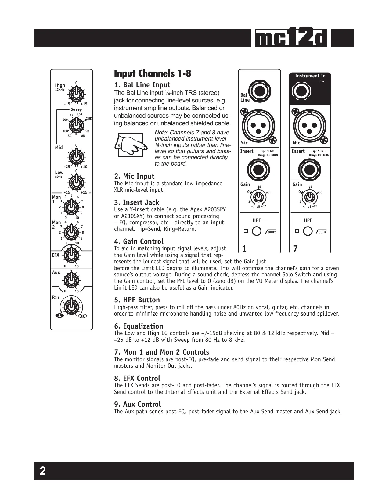
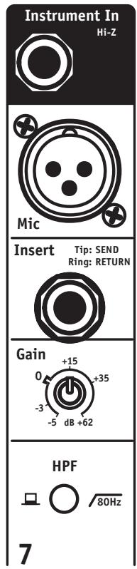
Input Channels 1-8
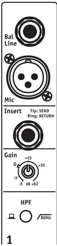
1. Bal Line Input
The Bal Line input 1/4 -inch TRS (stereo) jack for connecting line-level sources, e.g. instrument amp line outputs. Balanced or unbalanced sources may be connected using balanced or unbalanced shielded cable.

Note: Channels 7 and 8 have unbalanced instrument-level 1/4 -inch inputs rather than line-level so that guitars and basses can be connected directly to the board.
2. Mic Input
The Mic input is a standard low-impedance XLR mic-level input.
3. Insert Jack
Use a Y-insert cable (e.g. the Apex A203SPY or A210SXY) to connect sound processing - EQ, compressor, etc - directly to an input channel. Tip=Send, Ring=Return.
4. Gain Control
To aid in matching input signal levels, adjust the Gain level while using a signal that rep
resents the loudest signal that will be used; set the Gain just before the Limit LED begins to illuminate. This will optimize the channel's gain for a given source's output voltage. During a sound check, depress the channel Solo Switch and using the Gain control, set the PFL level to 0 (zero dB) on the VU Meter display. The channel's Limit LED can also be useful as a Gain indicator.
5. HPF Button
High-pass filter, press to roll off the bass under 80Hz on vocal, guitar, etc. channels in order to minimize microphone handling noise and unwanted low-frequency sound spillover.
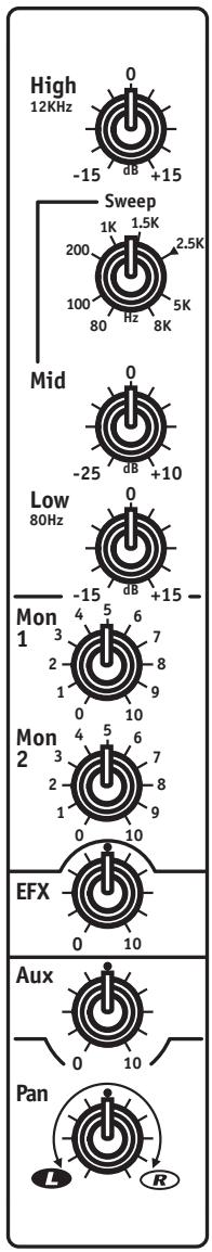
6. Equalization
The Low and High EQ controls are +/-15dB shelving at 80 & 12 kHz respectively. Mid = -25 dB to +12 dB with Sweep from 80 Hz to 8 kHz.
7. Mon 1 and Mon 2 Controls
The monitor signals are post-EQ, pre-fade and send signal to their respective Mon Send masters and Monitor Out jacks.
8. EFX Control
The EFX Sends are post-EQ and post-fader. The channel's signal is routed through the EFX Send control to the Internal Effects unit and the External Effects Send jack.
9. Aux Control
The Aux path sends post-EQ, post-fader signal to the Aux Send master and Aux Send jack.
10. Pan Control
The Pan control affects the main-mix signal (only) going to the L & R masters and the Media Out jacks.
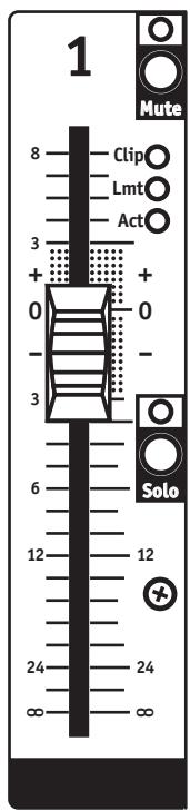
11. Mute Button
The Mute Switch disconnects the specified channel from all outputs. The channel can still be monitored through the Phones and on the VU-Meter when the Solo is activated in PFL mode.
12. Clip LED
The Clip LEDs Indicate the input Limiter's capacity has been exceeded, reduce the Gain setting when illuminated.
13. Limit LED
The Limit LEDs Indicate input Limiter activity. The brightness of the yellow Limit LED indicates the amount of gain reduction or compression.
14. Activity LED (Act)
The Act LED indicates channel signal activity (i.e. that signal is present in the channel).
15. Solo Button
When depressed, the Solo Switch isolates the selected channel through Phones and on the VU-Meter.
16. Channel Fader
The channel fader sends channel output to the L&R Masters and the Media outputs.
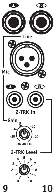
Input Channels 9/10 and 11/12
1. L&R Line Inputs
The L&R 1/4 -inch Line Inputs will accept balanced or unbalanced cables from keyboards, etc.
2. Mic Input
The Mic inputs accept standard low-impedance XLR mic-level input.
3. L&R RCA 2-Trk Input Jacks
The L&R RCA 2-Trk inputs can be used for audio signals from CD players, computers, iPods, etc.
4. Gain Control
The channel's Gain control regulates the L&R Line and Mic input signals.
5. 2-TRK Level Control
The 2-TRK Level Control regulates the 2-Trk (track) input signals only.
Note: Either the Line, or Mic input (not both), can be used along with the 2-Trk inputs simultaneously.
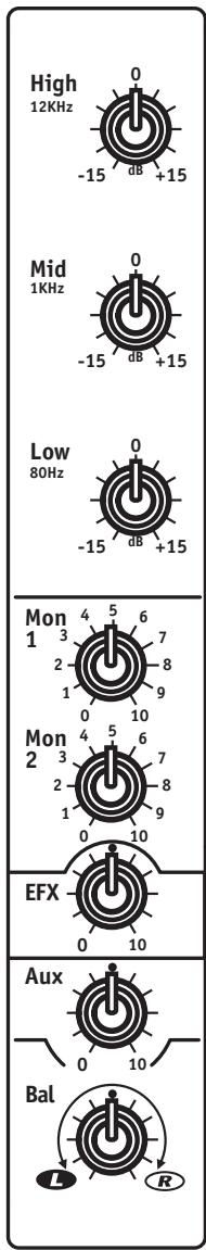
6. Equalization
The Low and High EQ controls are shelving at 80 Hz & 12 kHz respectively, Mid = bandpass at 1 kHz, all with +/-15 dB range.

1/4-inch Phone Plug

1/4-inch T.R.S. Phone Plug

XLR Plug
7. Mon 1 and Mon 2 Controls
The Mon 1 and Mon 2 controls are post-EQ and pre-fader; the audio signal is sent to the respective Mon Send masters and Monitor Out jacks.
8. EFX Control
The EFX control sends post-EQ, post-fader channel signal to the EFX Send Master and Internal Effects processor.
9. Aux Control
The Aux control sends post-EQ, post-fader signal to the Aux Send Master and Aux Send jack.
10. Bal Control
The Balance control affects the main-mix balance going to the L&R masters.
11. MUTE Switch
The Mute Switch disconnects the specified channel from all outputs. The channel can still be monitored through the Phones and on the VU-Meter when the Solo is activated in PFL mode.
12. CLIP LED
The Clip LED indicates the channel's signal capacity has been exceeded; reduce the Gain setting if continuously illuminated.
13. ACT LED
The Act (Activity) LED pulses with the input signal to indicate channel Activity
14. SOLO Switch
Use the Solo switch to isolate the channel through the headphone (Phones) amplifier and on the VU-Meter.
15. Channel Fader
The channel fader sends channel output to the L&R Masters and to the Media outputs.
Buss Inputs & Outputs
1. Sends
The 1/4 -inch EFX and Aux unbalanced mono outputs are controlled by their respective Send masters. Unbalanced cables can be used.
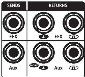
2. RETURNS
The 1/4 -inch L&R pairs of inputs (bal/unbal) are controlled by their respective EFX and Aux Rtn channels.
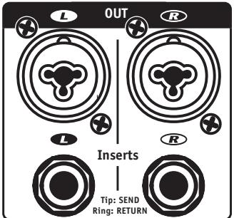
4. L&R Inserts
The L&R Insert 14 -inch TRS (stereo) jacks each acting as a send and a return (Tip=send, Ring=return) to permit patching EQ, compressor/limiter, etc. directly into the main mix outputs using 'Y' insert cables such as the Apex A210SPY or A210SXY.
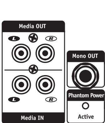
5. Media In
The Media In L&R RCA jacks go to the Media In master, which feeds the main buss (post Master) and can be used to connect the output of a second mixer or program source. Use balanced or unbalanced cables.
6. Media Out
The Media Out L&R RCA jacks are controlled by the Media Out master control. This is the main mix and can be connected to the input of another mixer or recording medium using balanced or unbalanced cables.
7. Mono Out
The Mono Out provides a main mix output regulated by the Mono Out Master control which is ideally suited for connecting a subwoofer amplifier. Use a balanced or unbalanced cable.
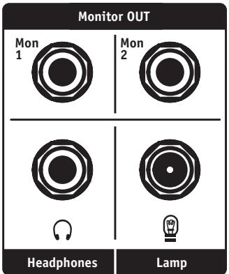
8. Monitor Out
The Mon 1 & Mon 2 14 -inch outputs are controlled by their respective Mon Send master controls. Use balanced or unbalanced cables.
9. Phantom Power Active LED
The Phantom Power Active LED indicates that phantom power is available on all Mic inputs. The Phantom Power Active switch is located on the same back panel as the AC switch and cable socket.
Note: phantom power will not interfere with the performance of most dynamic mics.
10. Headphone Output Jack
The Headphone Output jack enables the connection of standard stereo headphone which help to monitor all Input channels plus Main, Monitor, EFX and Aux busses. If no Solo switches are engaged, only the L&R Main mix will be present in the phones.
11. Lamp Connector
A standard BNC-mount gooseneck lamp such as our GNL-600, 12-Volt incandescent lamp or GNL-101 LED lamp can be used.
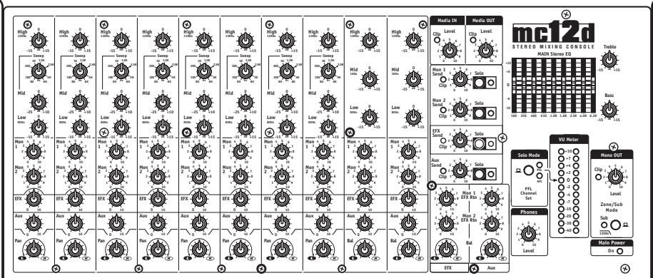
Master Controls
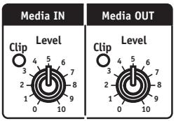
1. Media In and Out Master Controls and Clip LEDs
The Media In and Out Master controls regulate the input and output levels at their respective Media In and Media Out jacks. Reduce the level of the appropriate Media In master control when the Clip LED illuminates continually.
2. Mon 1 and Mon 2 Send Controls, Solo and Clip LEDs
The Mon 1 and Mon 2 Send controls regulate the level of their respective monitor busses going to the Mon 1 and 2 Out jacks. The Solo buttons isolate their respective moni
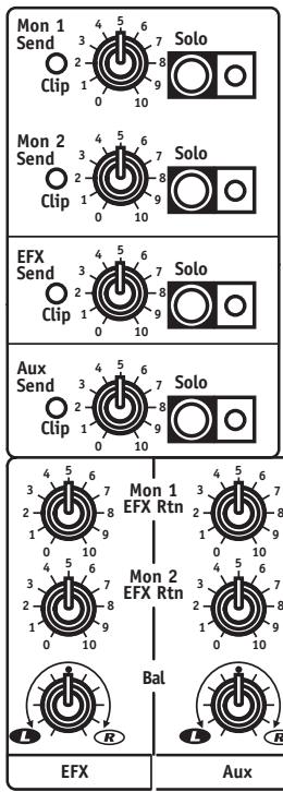
tor mixes through the headphones and the green LEDs indicate that the Solo feature is active. The red Clip LED indicates clipping in the buss; reduce the Send level or the channel Mon 1 or 2 levels to avoid distortion.
3. EFX Send, Solo Controls and Clip LEDs
The EFX Send, Solo controls regulate the level of the EFX mix going to the EFX Send jack and to the Internal Effects processor. The Solo Switch isolates the effects mix through the headphones and the green LED indicates that the Solo feature is active. The red Clip LED indicates clipping in the buss. Reduce the Send level or the channel EFX level control to avoid distortion.
4. Aux Send, Solo Controls and Clip LEDs
The Aux Send, Solo controls regulate the level of the Aux mix going to the Aux Send jack. The Solo Switch isolates the Aux mix through the headphones and the green LED indicates that the Solo feature is active. The red Clip LED indicates clipping in the buss. Reduce the Send level or the channel Aux level controls to avoid distortion.
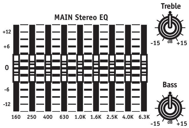
5. Main Stereo EQ, Bass and Treble Controls
The Main EQ sliders provide +/-12 dB of bandpass gain regulation at 9 frequencies from 160Hz to 6.3 kHz while Bass and Treble provide +/-15 dB of shelving throughout the overall low and high frequency ranges.
6. Solo Mode Switch and LEDs
By using the Solo Mode Switches, any channel in Solo mode is isolated on the VU-Meter for referencing their audio levels. By depressing the main Solo Mode switch, you choose PFL (pre-fade listen) to help setting the channel's Gain control for an average 0 dB reading. With the Switch down, you have after-fader listen mode to help you check the channel's overall signal level as regulated by its fader. With no channel or other Solo switches depressed, the meter reads the Main signal levels.
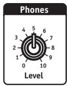
7. Phones Level
The Phones level control is used to adjust the volume of the signal sent to the Headphone jack.
8. Mono Out Section
The Mono Out section is used principally for remote control of subwoofer amplifiers, the L&R Main signal is mixed down to mono and available at the Mono Out jack. The Level control regulates output and the Sub Switch activates a 120Hz low-pass filter to facilitate no-crossover sub operation.
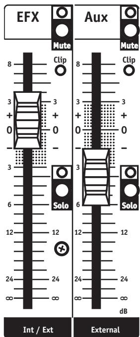
9. EFX and Aux Faders, Mute and Solo Switches and LEDs
The EFX and Aux faders control the amount of internal and external effects as well as auxiliary input signals being added to the Main mix. The Mute switches permit introducing effects and auxiliary inputs (e.g. from a second external effects chain) quickly and silently into the main mix and are associated with LEDs to indicate muting. The Solo switches let you listen to the effects alone through Phones and observe their signal levels on the VU-Meter. The Clip LEDs indicate whether or not the EFX and Aux Return levels need to be reduced.
10. Mon 1, Mon 2 EFX and Aux Return and Balance Controls
The Mon 1, Mon 2 EFX and Aux Return and Balance controls affect the internal effects, the external effects and Aux Return input signals which can be individually mixed to the monitors using these controls. The Bal control permits left and right EFX and Aux balancing.
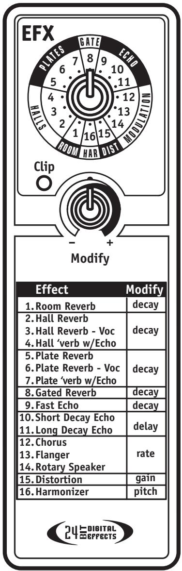
11. EFX Section
The onboard effects processor offers 16 delay/ reverb-oriented effects selectable by the rotary EFX selector and expanded by the Modify control. A Clip LED warns of excessive signal levels (turn down the master EFX send level).
Your new MC12D console comes with our unlimited 2-year warranty and is covered throughout Canada and the USA.
SPECIFICATIONS
Model: MC12D
Model ID: TYPE:YS1080
Number of Channels: 12
Channel Inserts: 1 to 8
Mono Channel EQ: (ch.1 to 8) High, Mid Sweep, Mid, Low
Stereo Channel EQ: (ch.9 to 12) High, Mid, Low
Channel Effects: All Channels
Monitors Effects: Yes
Balance Controls: 9 to 12
Pan Controls: 1 to 8
Channel Overload Protection: 1 to 8
Inputs - XLR (bal): 1 to 12
Inputs - 1/4-inch: 1 to 12
Inputs - RCA (unbal): 2 Stereo Sets and Rec In
Solo Switches: All Channels, Mon1, Mon2, EFX Sends and Returns
Mute Switches: All Channels
Hi Pass Switches: Channels 1 to 8
Activity / Solo LED: All Channels
Clip /Mute LED: All Channels
Phantom Power: 48V + LED indicator
VU Meter: 2 x 12 LEDs with Floating Peak
Headphone Monitor Features: Level, AFL/PFL Switch, 1/4 inch Stereo
Internal Effects: 16 Bit stereo, 16 Effects with Parameter Pot
Auxiliary Sends: 1 TRS
Effects Send: 1 Internal, 1 External
Effects Return: 2 stereo pairs on 1/4 inputs
Effects Return to Main: Yes
Effects Return to Monitor: Yes
Reverb / Effects Footswitch: Yes
Record Outputs: 1 Stereo RCA
Max Gain to Line Out-Mic Input (dB): 80
Max Gain to Line Out -Line Input (dB): 78
Master EQ -1 (type /Channels /Range - dB): Graphic / Stereo / 9 Band 160 Hz - 6300 Hz
Main Outputs ( Line Level): Main L/R (1/4 inch TRS, XLR)
Monitor Outputs (Line Level): Mon 1/2 (1/4 inch TRS)
Mixer - Signal to Noise Ratio (dB): Greater than 100
Mixer - Frequency Response (Tone and EQ Flat, +/-2dB):
Mixer - Input Referred Noise to line out, @ 150 Ohms (dBv): -123
Mixer THD (Main out w/ -10dB input): less than 0.03%
CMRR @ 60Hz (min/typ): 54 dB / 66 dB
Power Consumption (typ/max): 50 VA
Transformer Type: Toroidal
Finish: Scratch Resistant Vinyl-Coated Aluminum
Console Lamp Connector 12V DC (BNC): Yes
Dimensions (DWH, inches): 19.6x19.6x5.6
Dimensions (DWH, cm): 49.8x49.8x14.2
Weight (Ibs/kg): 19/8.6


1/4-inch T.R.S. Phone Plug

XLR Plug
Dimensions (PLH, pouces): 19.6x19.6x5.6
Dimensions (PLH, cm): 49.8x49.8x14.2
Poids (livres/kg): 19/8.6
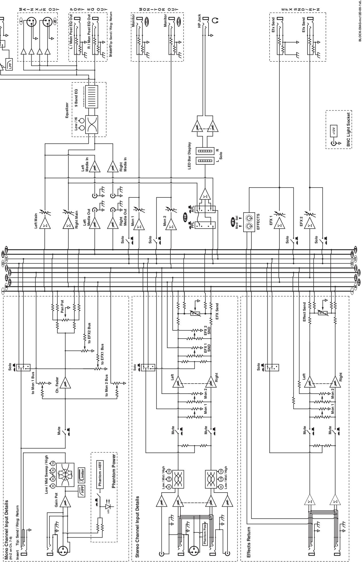
MODEL TYPE: YS1080 Block Diagram for MC12D DESIGNED & MANUFACTURED BY YORKVILLE SOUND
Unlimited Warranty
Yorkville's two and ten-year unlimited warranty on this product is transferable and does not require registration with Yorkville Sound or your dealer. If this product should fail for any reason within two years of the original purchase date (ten years for the wooden enclosure), simply return it to your Yorkville dealer with original proof of purchase and it will be repaired free of charge. This includes all Yorkville products, except for the YSM Series studio monitors, Coliseum Mini Series and TX Series Loudspeakers.
Freight charges, consequential damages, weather damage, damage as a result of improper installation, damages due to exposure to extreme humidity, accident or natural disaster are excluded under the terms of this warranty. Warranty does not cover consumables such as vacuum tubes or par bulbs. See your Yorkville dealer for more details. Warranty valid only in Canada and the United States.
Garantie Illimitée
Voice: (716) 297-2920
Fax: (716) 297-3689

Niagara Falls, New York
14305 USA

WEB: www.yorkville.com
Niagara Falls, New York
14305 USA
Voice: (716) 297-2920
Fax: (716) 297-3689

Quality and Innovation Since 1963
Printed in Canada
Manual-Owners-MC12D-00-1v0 · March 16, 2010
- IMPORTANT SAFETY INSTRUCTIONS
- CAUTION: TO REDUCE THE RISK OF ELECTRIC SHOCK, DO NOT REMOVE COVER (OR BACK).
- Power Sources
- Hazards
- Power Cord
- Service
- SUVEZ TOUTES LES INSTRUCTIONS
- MC12D 12-Channel Mixer
- Introduction
- Features at a Glance
- Input Channels 1-8
- Bal Line Input
- Mic Input
- Insert Jack
- Gain Control
- HPF Button
- Equalization
- Mon 1 and Mon 2 Controls
- EFX Control
- Aux Control
- Pan Control
- Mute Button
- Clip LED
- Limit LED
- Activity LED (Act)
- Solo Button
- Channel Fader
- Input Channels 9/10 and 11/12
- L&R Line Inputs
- L&R RCA 2-Trk Input Jacks
- 2-TRK Level Control
- Bal Control
- MUTE Switch
- ACT LED
- SOLO Switch
- Channel Fader
- Buss Inputs & Outputs
- Sends
- RETURNS
- L&R Inserts
- Media In
- Media Out
- Mono Out
- Monitor Out
- Phantom Power Active LED
- Headphone Output Jack
- Lamp Connector
- Master Controls
- Media In and Out Master Controls and Clip LEDs
- Mon 1 and Mon 2 Send Controls, Solo and Clip LEDs
- EFX Send, Solo Controls and Clip LEDs
- Aux Send, Solo Controls and Clip LEDs
- Main Stereo EQ, Bass and Treble Controls
- Solo Mode Switch and LEDs
- Phones Level
- Mono Out Section
- EFX and Aux Faders, Mute and Solo Switches and LEDs
- Mon 1, Mon 2 EFX and Aux Return and Balance Controls
- EFX Section
- SPECIFICATIONS
- Unlimited Warranty
- Garantie Illimitée
Brand : YORKVILLE
Model : MC12D
Category : Sound system