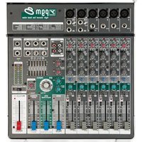
M8 - Audio Mixer YORKVILLE - Free user manual and instructions
Find the device manual for free M8 YORKVILLE in PDF.


User questions about M8 YORKVILLE
0 question about this device. Answer the ones you know or ask your own.
Ask a new question about this device
Download the instructions for your Audio Mixer in PDF format for free! Find your manual M8 - YORKVILLE and take your electronic device back in hand. On this page are published all the documents necessary for the use of your device. M8 by YORKVILLE.
USER MANUAL M8 YORKVILLE
2 x 85 Watt Powered Mixer
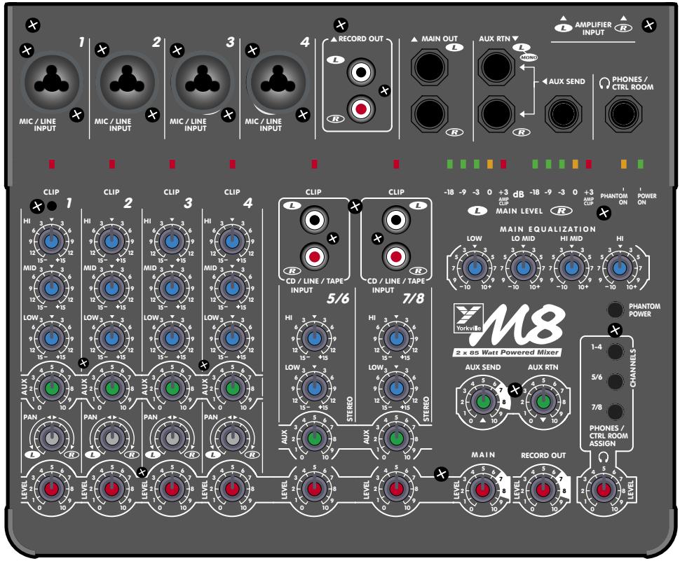
TYPE: YS1024
OWNER'S MANUAL
MANUEL DE L'UTILISATEUR
IMPORTANT SAFETY INSTRUCTIONS

INSTRUCTIONS PERTAINING TO A RISK OF FIRE, ELECTRIC SHOCK, OR INJURY TO PERSONS
CAUTION:
TO REDUCE THE RISK OF ELECTRIC SHOCK, DO NOT REMOVE COVER (OR BACK).
NO USER SERVICEABLE PARTS INSIDE.
REFER SERVICING TO QUALIFIED SERVICE PERSONNEL.
Read Instructions
The Owner's Manuals should be read and understood before operation of your unit. Please, save these instructions for future reference.
Packaging
Keep the box and packaging materials, in case the unit needs to be returned for service.
Warning
When using electric products, basic precautions should always be followed, including the following:
Power Sources
Your unit should be connected to a power source only of the voltage specified in the owners manual or as marked on the unit. This unit has a polarized plug. Do not use with an extension cord or receptacle unless the plug can be fully inserted. Precautions should be taken so that the grounding scheme on the unit is not defeated.
Hazards
Do not place this product on an unstable cart, stand, tripod, bracket or table. The product may fall, causing serious personal injury and serious damage to the product. Use only with cart, stand, tripod, bracket, or table recommended by the manufacturer or sold with the product. Follow the manufacturer's instructions when installing the product and use mounting accessories recommended by the manufacturer.
The apparatus should not be exposed to dripping or splashing water; no objects filled with liquids should be placed on the apparatus.
Terminals marked with the "lightning bolt" are hazardous live; the external wiring connected to these terminals require installation by an instructed person or the use of ready made leads or cords.
No naked flame sources, such as lighted candles, should be placed on the apparatus.
Power Cord
The AC supply cord should be routed so that it is unlikely that it will be damaged. If the AC supply cord is damaged DO NOT OPERATE THE UNIT.
Service
The unit should be serviced only by qualified service personnel.
INSTRUCTIONS RELATIVES AU RISQUE DE FEU, CHOC ÉLECTRIQUE, OU BLESSURES AUX PERSONNES
AVIS:
AFIN DE REDUIRE LES RISQUE DE CHOC ELECTRIQUE, N'ENLEVEZ PAS LE COUVERT (OU LE PANNEAU ARRIERE)
NE CONTIENT AUCUNE PIECE
REPARABLE PAR L'UTILISATEUR.
CONSULTEZ UN TECHNICIEN QUALIFIE
POUR L'ENTRETIENT
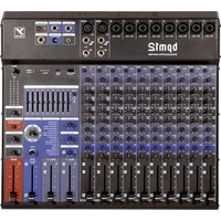
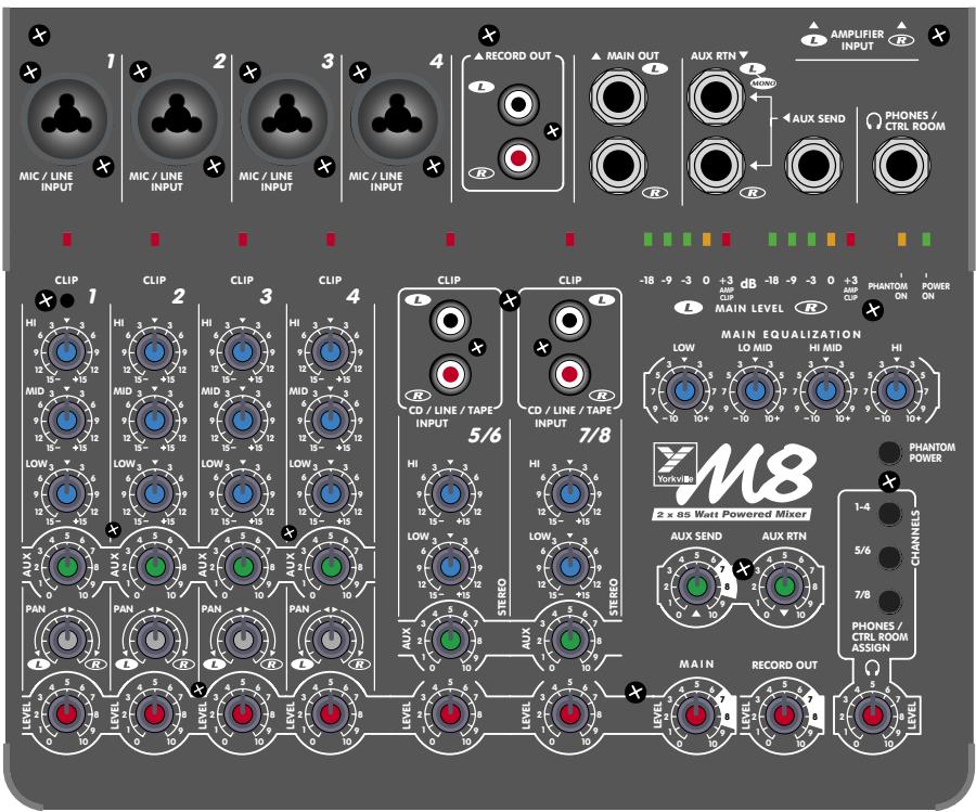
Your new M8 Mixer/Amplifier is designed and built to provide long-term trouble free performance. Drawing on over thirty years of experience in the design and manufacture of powered mixing consoles, Yorkville engineers were able to optimize the design of the M8 greatly. Including comprehensive features such as quiet internal fan cooling, four microphone input channels, two stereo input channels, headphone monitoring, phantom power, 4-band main EQ, dual level-meters, 170 watts of stereo power built-in, and powered by an advanced switching power supply that allows you to connect the power plug of your M8 into any wall socket around the world!
101 Uses for an M8
There may not be exactly 101 uses for an M8, but the M8 was designed to be an extremely versatile audio mixer for its size. With 8 inputs and 4 separately level-controlled outputs, the M8 is capable of handling almost any basic audio mixing need. Here are some application suggestions:
- Rehearsal room sound system (economical)
- Small performing acts (compact and economical)
- Auction public address system (compact and economical)
- Fashion shows (compact, economical, microphone for the host and stereo inputs for background music)
- Sub-mix mixer (not enough inputs to the snake on stage? Use an M8 to mix down 4 inputs into 1 and at the same time plug in some stage monitors!)
- Multi-media presentations in boardrooms, trade shows, and seminars (compact, economical, microphone for presenter, and stereo inputs for video presentations
- Church audio system (economical, and capable of sending the program audio to several rooms and audio services such as infra-red transmission)
- Back-up sound system (an economical, compact audio mixer and power amplifier that can be pulled out in dire times)
- Auditorium sound system (set the system up, lock it away and turn it on by a remote power switch)
- Amusement park sound system (send triggered audio sources to several destinations)
- Multi-zone paging audio system (economical and versatile)
- Live theatre (economical and versatile)
and many, many more...

1/4-inch Phone Plug

1/4-inch T.R.S. Phone Plug

XLR Plug
Terminology
- 3-pin microphone inputs are referred to as XLR connectors.
- 1/4-inch jack sockets are called phone connectors.
- Balanced 1/4-inch inputs or outputs are called TRS or Tip-Ring-Sleeve
- Master control and mixing channels are called busses.
- Overload indicators are called Clip LED's.
- Patch cables with dual conductors plus shielding and ring-tip-sleeve (stereo) 1/4-inch phone plugs are referred to as balanced patch cables.
Basic Features
Channels 1 - 4
- XLR Microphone and balanced TRS Line inputs with low-noise input circuit design.
- Balanced Line inputs accept either balanced or unbalanced lines.
- Phantom power (24 volts).
- Extremely wide input GAIN-adjustment.
- AUX send controls are post-EQ.
- Three-band EQ with +/-15 dB of range.
- Pan controls provide constant gain levels at all settings.
- Increased circuit headroom and gain for a more flexible mix.
- Clip LED's indicate even the briefest peaks, and fire at -3dB, well before the onset of actual clipping, at any active channel stage.
Stereo Channels 5/6 & 7/8
- Left and Right RCA inputs.
- Low and High frequency-shelving EQ (+/- 15dB).
- AUX send controls are post-EQ.
Master Features
- The Main Level control receives the audio signal from the Channel Level controls, adjusts the gain, and sends the signal to the Main EQ.
- The Record Level control receives the audio signal from the Channel Level controls, adjusts the gain, and sends the signal to the Record Out RCA jacks.
- The AUX Send control receives the audio signal from the Channel AUX controls, adjusts the gain, and sends the signal to the AUX Send output jack.
- The AUX Return control receives the audio signal from the AUX Return jacks, adjusts the gain, and sends the signal to the Main Level control.
- The Phones/Control Room level controls the headphone amplifier gain. The Phones/Control Room Assign switches allow the user to select channels 1-4, or stereo channel 5 / 6 , or stereo channel 7 / 8 or any combination or all three selections and send the audio signal to the Phones/Control Room level control.
Power Amplifier Features
- A total output of 170 watts with well-proven, reliable Audiopro technology.
- Industry leading specifications for distortion, damping, and efficiency.
- Comprehensive protection against low or even shorted loads, and overheating.
- Hi-Current 1/4-inch output connectors.
Power Supply
Your M8 contains a universal power factor corrected switch mode power supply. What is that and why should you care? Well let me tell you:
universal: means that you can power your M8 from any wall receptacle around the world from 90 to 275 VAC, 50 or 60Hz .
power factor corrected: means that the power supply makes the best use of every watt of power the M8 draws from the wall receptacle. Better than any conventional power amplifier.
switch mode power supply: is a power supply that delivers the same operating power supply voltages to the circuitry inside the M8, even if the hydro source voltage sags down to 90 VAC. So the 2 × 85 watt power amplifier will deliver 2 × 85 watts at a hydro voltage from 90 to 275 VAC. Only the latest hi-tech touring power amplifiers can claim to do the same. A conventional 100 watt amplifier without a switch mode power supply will deliver 100 watts to the loudspeaker at 120 VAC, but only deliver 56 watts with a hydro voltage of 90VAC. The M8 will deliver 2 × 85 watts at 90VAC!
Input Wiring tips:
- For all input conductivity use shielded wire only. Cables with a foil shield or a high-density braid are better.
- When changing input connections, turn down the level controls on the mixer to eliminate pops and thumps out of the loudspeakers as the cable contacts the mixer.
- Keep input connection cables as short as possible to minimize noise and hum pick-up.

Feature Details & User Tips
Channel Strips 1-4
Inputs
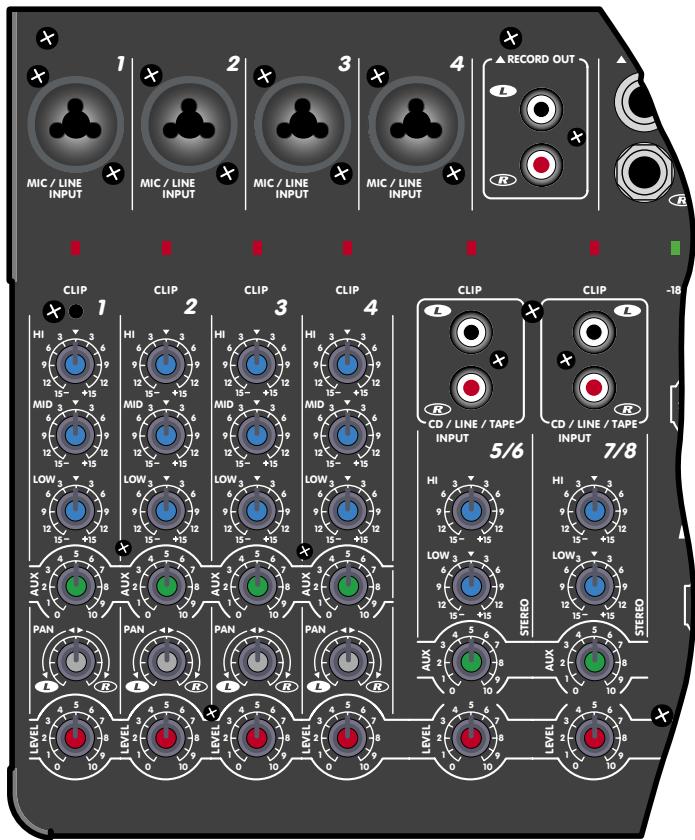
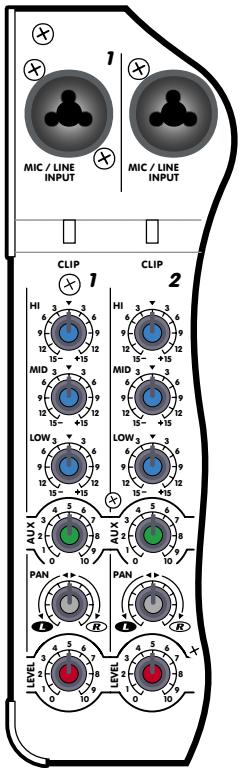
Each channel has both a combination Mic and Line input. The Line input will accept either balanced or unbalanced signals from all types of sources and the Mic input is optimized for low-impedance microphones. The Line input is Tip-Ring-Sleeve balanced, with the Tip in phase, the Ring reverse phase and the sleeve, Ground. The XLR is wired Pin 1= Ground, Pin 2 = in phase & Pin 3 = reverse phase. This configuration is the standard throughout the world.
Problem: Hum and Buzz. Unbalanced connections may be made to the Line input with an unbalanced shielded cable. However, magnetic field or leakage-induced ground currents between separate pieces of audio equipment can sometimes produce hum and buzz. Most electronic musical instruments, for example, still use unbalanced connections.
CAUTION: We urge you to
never remove the ground-pin on the AC cord or otherwise disable the earth safety Ground connection as doing so can expose you to a serious shock hazard. Additionally, your radio interference problems will increase and in some cases your hum problems will get even worse.
Solution: Hum and buzz can be safely reduced or eliminated with the M8's input balancing, even when the signal source is unbalanced, Simply use standard Tip-Ring-Sleeve balanced patch cables. However, in some worst-case instances it may be necessary to create a special patch cable. In this case, use a 1/4-inch TRS (stereo) cable.
Method: Attach a 1/4-inch TRS (stereo) plug to the end which will plug into the mixer's balanced-input as follows; 1) solder shield to Sleeve, 2) solder wire #1 to Tip, 3) solder wire #2 to Ring. Now attach the mono plug to the other end of the cable as follows: 4) solder the shield and wire #2 to the Sleeve, 5) solder wire #1 to the tip. Now connect this mono end to the output of the unbalanced piece of equipment and the stereo end to the M8's Line input. This technique will always reduce hum, and it can be used to connect any equipment having a Balanced INPUT to any other equipment having an Unbalanced OUTPUT.
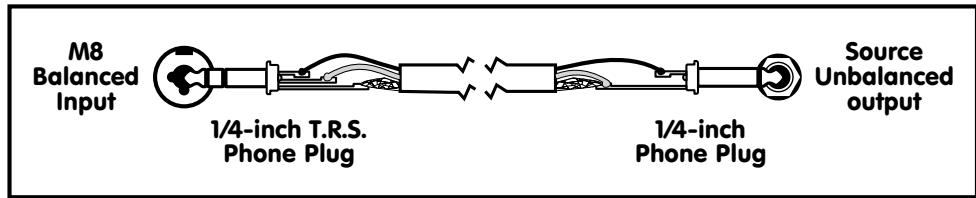
Hum Reducing Cable
Phantom Power Button & LED
Located on the front panel near the Phones/Control Room Assign switches, this push-button activates the 24 Volt Phantom Power feature built into the M8. When the Phantom Power is activated, the +24V LED on the front panel (beside the POWER ON LED) will illuminate. Now you may connect condenser microphones to channels 1 - 4 without the need for external power supplies. You may also connect dynamic microphones to these channels with the Phantom Power activated without any problems or loss of sound quality.
Channel Level Control
First adjust the Main Level control to the shaded area (7 to 8 on the level scale). With a signal applied to the input, adjust the Channel Level control until the appropriate audio level is heard out of the loudspeaker. If the Clip LED for the channel that you are adjusting is blinking then turn the Channel Level down until the Clip LED blinks occasionally. This will ensure that the signal level fits comfortably within the channel strip's headroom low enough to prevent distortion, and yet high enough to preserve the signal to noise ratio. This control covers a wide range, so it may seem rather sensitive until you're used to it.
3-Band EQ
Equalization is varied by three controls labeled High, Mid, and Low. Each control can either boost or cut the amplitude of its frequency band by 15dB. This is a considerable amount of gain change, roughly equivalent to a 150% variation in audible loudness. It is therefore wise to use boost settings of not more than +3dB to +6dB in order to avoid feedback and/or distortion.
On the other hand, -15dB of CUT-capability can come in handy for solving certain microphone or line problems. For example, substantial Low and High cuts can help get rid of feedback plus puffing and thumping noises from harmonica microphones. Flattop guitar microphones or transducers can often benefit from a slight Mid cut to fatten the sound, and direct or miked bass inputs usually benefit from a fairly substantial Low cut to avoid main system distortion.
Channel AUX Level Control
The Channel AUX Level control varies the amount of post-equalizer, channel signal sent to the master AUX bus. The output of the AUX bus goes first to the AUX Send Level Control, then to the AUX Send jack.
Pan (or balance) Control
This control directs the post-fader mono output of the channel to the Left and Right Main masters. In a stereo setup, the Pan should be set to the 12 o'clock position so that the aural image of the audio signal is in the center of the stereo listening field. The pan control can be turned clockwise or counterclockwise to move the image of the channel's audio signal to the right or the left channel.
Clip LED
The channel Clip LED watches all the active electronic stages in the channel circuit. Whenever any stage's signal peak approaches clipping to within 3dB, the Clip LED circuitry captures and displays this event. See under Channel Level control for more about this feature.
Channel Strips 5/6 & 7/8
Inputs
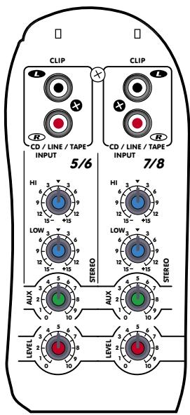
Each channel has a pair of RCA input jacks for the left and right input signals. Using jack adapters such as 1/4 -inch phone to RCA will allow any line level signal to enter these channels.
Input Wiring tips:
- For all input conductivity use shielded wire only. Cables with a foil shield or a high-density braid are better.
- When changing input connections, turn down the level controls on the mixer to eliminate pops and thumps out of the loudspeakers as the cable contacts the mixer.
- Keep input connection cables as short as possible to minimize noise and hum pick-up.
Channel Level Control
First adjust the Main Level control to the shaded area (7 to 8 on the level scale). With signal applied to the input, adjust the Channel Level control until the appropriate audio level is heard out of the loudspeaker. If the Clip LED for the channel that you are adjusting is blinking then turn the Channel Level down until the Clip LED blinks occasionally. This will ensure that the signal level fits comfortably within the channel strip's headroom low enough to prevent distortion, and yet high enough to preserve the signal to noise ratio.
2-Band EQ
Two controls labeled High, and Low vary equalization. Each control can either boost or cut the amplitude of its frequency band by 15dB.
User tip: Use the channel EQ controls to "shape" the desired sound for the audio coming into that channel. The source for channels 5/6 may be different than the source for channels 7/8. That's why there are separate tone controls for each chan-

nel. The Main Equalization controls are used to "shape" the over final mixed sound to suit the loudspeakers used and to compensate for the acoustics of the room.
Channel AUX Level Control
The Channel AUX Level control varies the amount of post-equalization, channel signal sent to the master AUX bus. The output of the AUX bus goes first to the AUX Send Level Control, then to the AUX Send jack.
Master Section
- The Main Level control receives the audio signal from the Channel Level controls, adjusts the gain, and sends the signal to the Main Equalizer. The shaded area on numbers 7 & 8 of
the numbered scale surrounding the control indicate the optimum setting region for this control. Operating the control in this region will provide the best in gain and low noise for typical operation. Not to say that the control must be operated in this hi-lighted region, it is only a suggestion for the best audio performance. This control is used to turn down the overall audio output to the Main Out and to th power amplifiers. Treat it like the volume control on a stereo, as it would adjust the audio signal to the desired listening level.
-
The Record Level control receives the audio signal from the Channel Level controls, adjusts the gain, and sends the signal to the Record Out RCA jacks. This control operates in the same way as the Main Level control. Your recording will have reduced noise if the Record Level is set within the shaded area and the input level control at your recorder is adjusted for a 0Vu level.
-
The AUX Send control receives the audio signal from the Channel AUX controls, adjusts the gain, and sends the signal to the AUX Send output jack. The shaded area on numbers 7 & 8 of the numbered scale surrounding the control indicate the optimum setting region for this control. The AUX Send signal can be used as a Monitor Send (the audio
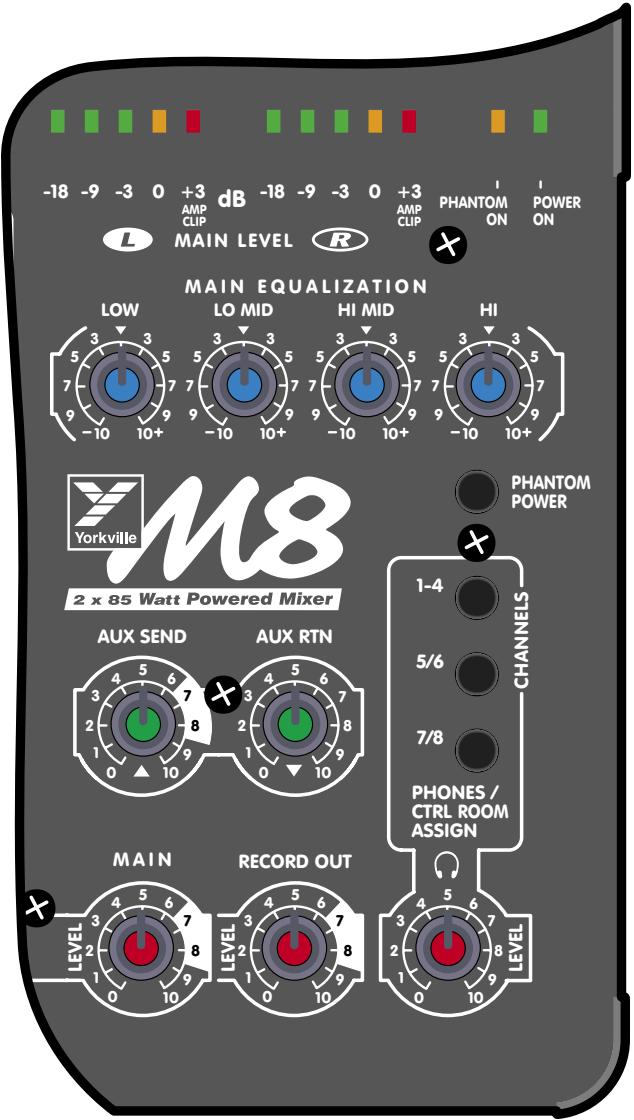
signal would pass through a separate power amplifier and power stage monitors), an Effects Send (the dry audio signal that would enter an effects processor), or through an amplifier to loudspeakers located in another room (another audio zone).
- The AUX Return control receives the audio signal from the AUX Return jacks adjusts the gain, and sends the signal to the Main Level control. The shaded area on numbers 7 & 8 of the numbered scale surrounding the control indicate the optimum setting region for this control, but depending on how large the signal is coming from other audio equipment, this control will probably be set from 3 to 8. The AUX Return signal may come from the output of an effects processor, or a stereo signal from a CD or cassette player. If the source equipment is mono insert the signal into the L Mono AUX RTN jack and the audio signal will appear on the left and right channels of the AUX RTN Level control. If the source equipment is stereo, insert the signal into the L and R jacks and a stereo signal will appear at the AUX RTN Level control.

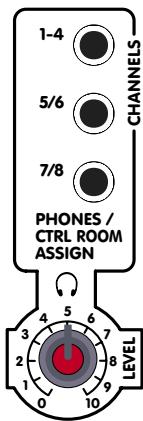

- The Phones/Control Room level controls the headphone amplifier gain. The Phones/Control Room Assign-switches allow the user to select channels 1 - 4, or stereo channel 5/6, or stereo channel 7/8, or any combination, or all three selections and send the audio signal to the Phones/Control Room level control. This feature allows the user to monitor the separate channel audio signals, and listen to the sound quality of individual musical instruments, or press all three Control Room Assign-switches down and use the Phones/Control Room output to feed a control room monitor, or an amplifier to loudspeakers located in another room (another audio zone). To "cue" an audio track before playing the music through the mixer, turn down the Channel Level to 0 and plug your headphones into the phone jack on your source audio equipment. When you have found the starting point of your music passage, pause the player, return the Channel Level to the original turned-up setting and press play on the source equipment at the appropriate time.
If you are sending the PHONES/CTRL ROOM signal to another piece of audio equipment, use a TRS cable (in this case to be used as a stereo cable), as the left and right channel signals are present in the PHONES/CTRL ROOM jack. If a mono cable is used, the left channel signal will get shorted to ground by the mono cable inside the jack. This could result in the headphone amplifier becoming hot and the right channel audio signal becoming distorted.
Level Meters
These meters indicate the Left and Right Main bus audio levels. If either or both of the +3dB amp clip lights at the top of the level meters are flashing too much of the time, lower the Main Level control to avoid possible distortion on peaks.
Amplifier Inputs L & R
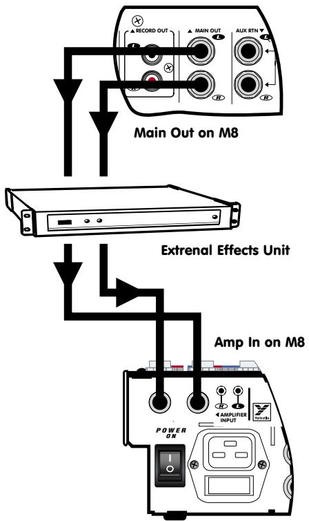
These are switching jacks that enable you to directly access either or both channels of the built-in power amplifier while disconnecting the normally connected source the Main EQUALIZER. This permits you to insert an external-EQ, a processor /crossover (e.g. elite) or a compressor/limiter between the mixer section's Main OUTPUTS and the AMP 1 & AMP 2 INPUTS thus providing the 100% signal processing.
Power Amplifier
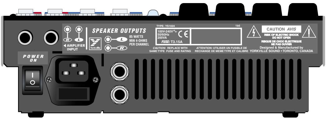
The M8 has a built-in 170-watt stereo power amplifier. Each channel has an input sensitivity of +4dBv (1.4 volts RMS) for full-power output and each can deliver over 85 watts into a 4-ohm speaker load. These amplifiers incorporate computer designed internal heatsinks and a variable-speed fan which automatically provides quiet operation consistent with cooling requirements. Cool air is drawn into the front of the mixer, and heated air is expelled out of the back. Even at maximum power, this arrangement results in quiet, dependable performance.
PLEASE NOTE: The air vents at the front and rear of the mixer are essential for proper operation. Blocking the free flow of air through the mixer will result in system shutdown due to overheating. Repeated overheating may eventually cause damage. Please keep the vents free of obstructions.
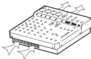
Speaker Connections
Two 1/4-inch jacks provide the loudspeaker connection to the power amplifier (one jack per channel). A minimum 4-ohm loudspeaker load may be connected to each jack. To connect two 8-ohm loudspeaker loads to one channel (the two 8-ohm loads in parallel equal a 4-ohm load), connect one loudspeaker cable from one loudspeaker to a speaker output jack. Connect the second loudspeaker on that channel to the second jack on the rear of the first loudspeaker. Repeat the procedure for the other speaker output channel.
Power Amplifier Protection
The M8's power amplifier is protected from damage due to open, shorted or excessively low speaker loads. It will continue to run into a low (less than 4-ohms) overall speaker impedance, or even into a total short-circuit for a brief time, however the amplifier's defense system will be activated. First, the amplifier will enter current limit. Then, if the condition worsens, a thermal protection circuit will shut the power amplifier down. When this happens, check your system for restricted air intake/exhaust at the M8. Also check for shorted loud-speaker cables or connectors and/or reduce the number of speakers being driven. In a few minutes when it has had a chance to cool down, the power amplifier will recover.
a. If the power amplifier shuts down as above, the mixer section will continue to function. This means that, if the M8's power amp fails to come back on (unlikely) and you have a spare power amplifier available, you can connect it to the M8 via the Main Output jacks
b. Because the amplifier is also protected against open-circuit conditions, you may use the M8 without any speakers connected, for example if you wanted to do some recording.
AC Power Fuse
Located on the back panel near the Speaker connectors, the fuse's main function is to shut the M8 down completely in case of an AC power overload. If the fuse blows replace with the same type fuse. If upon turning the unit on the second fuse blows, have your M8 serviced by a qualified Yorkville Service Centre.
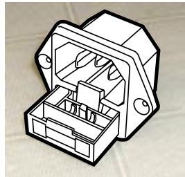
IEC Receptacle with Fuse Holder and Spare Fuse Compartment
General Operating Instructions
- Connect the AC power cord to a 120 to 240 Volt AC grounded power outlet.
- Turn the Main and Monitor Master controls to 0 (min) for now, then turn on the Power switch.
- Connect low-impedance microphones to the 3-pin XLR type Microphone inputs (ch. 1 to 4).
- Connect high-impedance microphones or mono line-level signal sources - i.e. the output of a mono-mixer, an electric instrument, etc. to the combination1/4-inch/XLR BAL Line IN jacks.
- Connect stereo sources - tape deck, CD-player, stereo keyboard, instrument, etc. to channels 5/6 and 7/8, via the RCA (phono) type inputs. Stereo sources may be connected to channels 1 through 4 if you use two of them, one panned left, the other right.
- Using speaker cables (see under Speaker CONNECTIONS) connect one or two 8-ohm or one 4-ohm speaker to the L SPEAKER OUTPUT on the back panel. Similarly, connect one or two 8-ohm or one 4-ohm speaker to the R SPEAKER OUTPUT.
- Position your main PA speakers at the front of the stage, pointing directly out at the audience. If you use a separate monitor amplifier, connect the AUX Send output to the amplifier input and after connecting the monitor loudspeakers to the amplifier's output, position your monitor speakers on the stage floor, in front of the microphone stands, pointing up at the backs of the microphones (remember to use cardioid or uni-directional microphones to reduce the threat of monitor feedback).
- During a sound check with the band playing or other sources feeding the mixer inputs, make the following control adjustments:
a) Set the channel Low, Mid & High EQ controls and PAN controls at center. Now set the Channel Level, and AUX Level controls to 0, and the Main EQ controls at the center position.
b) Set the Main Level control to 7.
c) Now bring up the channel level faders slowly until each channel can be heard at the desired volume level through the main PA speakers.
d) If the AUX Send is being used as a stage monitor output, turn up the channel AUX
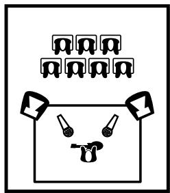
Keep the Main Speakers between mics and audience to minimize feedback
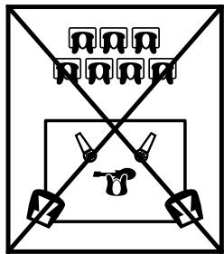
DO NOT place Main Speakers in back of the stage!!

Level controls until the performers can hear themselves on the stage at adequate volume levels without feedback.
- Feedback during a performance is usually caused by one of the stage monitors. The main PA is less likely to feed back because the microphones are so far away from the main PA speakers. Therefore, if one of the monitors and a microphone are feeding back, try the following procedures
a) Turn the AUX Send channel level controls to 0.
b) Turn each AUX Send channel level control up one at a time until you find which channel is causing the feedback at a low level.
c) Reposition the microphone for the channel causing the feedback further away from the stage monitor closest to the microphone.
d) Now turn the rest of the AUX Channel controls and the AUX Send master control back up. If the feedback recurs, repeat the procedure b) and c) until you have gained enough headroom below the feedback threshold.
e) In the rare case of main system feedback, follow the above type of procedure, but using the Main Level, and Channel Level controls.
Note: To increase your sound system's immunity towards feedback a graphic equalizer could be inserted between the Main Output jacks and the Amplifier Input jacks. Then the audio signal passing from the mixer to the amplifiers will flow through the off board equalizer. Then as the Main Level control is turned up to the point where feedback occurs, pull down each band control (which reduces the gain of the sound system at the frequency marked on that band of the equalizer) on the off board equalizer one at a time until the feedback disappears. It is best if the least amount of adjustment is made on the off board equalizer as too much gain reduction will greatly change the tonal quality of your music.
Tips on Getting a Good Mix
If you've never mixed at high power levels before, the following suggestions may help you to get a consistently good sound.
Feedback
When you have live microphones, don't run the volume level right up to the point of feedback! This is the most common mistake made by people mixing live events. We've all heard systems on the verge of feedback and they sounded terrible, even when no feedback was actually occurring! This happens because working at the feedback point warps the frequency response of the system.
To understand how volume level can affect frequency response, lets look at what happens as you increase it to the point of feedback. Notice that feedback wants to occur at a certain frequency? This is because the entire system - the room, the microphones, the speakers, the people, everything - is showing a tendency to Resonate at a particular frequency. You can see the effect of resonance when you talk into an empty tin can. You hear a hollow droning sound. The technical term for a system that shows a tendency to resonate is a High Q Filter. So by turning up to the feedback point, you are making the whole system behave like a high Q filter. This gives you the same sound as if you turned everything down a lot and then boosted, say, the 1KHz graphic equalizer to +12dB!
This is why cutting certain frequencies with the graphic equalizer can control stage feedback. However, using the graphic to control feedback means that, as the room changes, (more people come in, it gets hotter, the dance floor empties or fills up, etc.), the system's equalization will change as the rooms resonance changes. You'll be fighting the room all night.
Having things loud doesn't make up for the poor sound produced by spurious response peaks. Fortunately, the Q of a system decreases rapidly as gain drops. The professional way to avoid resonance effects is to keep about 3dB (30% lower) from the first sign of feedback. The system will still be very loud, but it will sound a whole lot better. Ideally, the graphic equalizer should be used to flatten the overall response, not to fix feedback.
Reverb
If you are using reverb, use short reverb sounds and modest amounts of reverb. Long reverberation effects cause the music to smear and can make things sound out of tune, especially as the music goes through harmonic changes. Shorter reverb decay will enhance the sound without spoiling definition. Don't forget that the room you are in may have lots of its own reverberation, and that you can't hear that in the headphones.
Tone Controls
Use tone controls sparingly. Most audio sounds great just as it was created. A little high-end boost can bring vocals to life. If you have a microphone on the bass drum, you can probably roll off most of the treble. (It's not useful to have microphones listening for sounds that aren't there). Experiment, but be conservative with tone controls.
Vocals
Keep the vocals up front. The instrument's sound is there to accompany the vocalist. Therefore the vocalist should be heard at a louder level than the instruments. But don't keep turning up the vocal microphone or you will experience feedback. Just turn the Channel Level controls for the instruments down a little and you will achieve the same result without the possibility of feedback.
Hearing
Speaking of ears, don't forget yours. You've probably walked into a show late in the evening and had your ears blistered by screaming horns. "What's wrong with whoever is doing the mix?" you might have said with fingers in your ears. What was wrong was a technician with a dose of hearing fatigue and his/her unfortunate reaction to it. After a relatively short exposure to high sound pressure levels, the human ear shuts down (somewhat), especially in the upper-midrange and high frequencies where it is most sensitive. This process reduces the immediate discomfort, but there is debate as to whether it protects the ear in the long term and much evidence that damage does occur. In any case, the technician notices that the horns sound muted and reacts by altering the equalizer. Apart from long-term physical danger, this sounds bad and turns off at least some of the audience - especially the new arrivals. The solution is to use earplugs or other hearing protection. Afterwards, some quiet time is in order to give damaged eardrum tissue a chance to heal. Provided severe or repeated damage hasn't created a buildup of scar tissue causing permanent hearing loss, you can return to hear your mix with fresh ears. The mix should sound invitingly loud, but not painful. In basic terms, if you find that you've turned up the high end since the night began and it still sounds the same to you as it did at the beginning, watch out. That's not "fatigued horns" or "changing room acoustics" rolling off the high end, it's your ears. Please do yourself and your audiences a favor - Use Earplugs! And if you can't bring yourself to do that, be considerate of your audiences and leave the high-end equalizer or crossover at normal settings.
Finally, remember why the sound system is there and what people did before sound reinforcement was created. They listened in close proximity to a group of performers. But times have changed and large groups gather to hear artists perform. The purpose of the sound system is to amplify the sound created by the performers so that the audience can COMFORTABLY hear the music with the same tonal quality as if they were standing at the front of the stage.
The M8 was designed for a quick easy set-up, remaining invisible and reliable during the performance, and light to carry at 3:00 in the morning.

Introduction
1/4-inch T.R.S. Phone Plug

XLR Plug
Terminologie
Number of Channels 8
Mono Channel EQ Low, Mid, High
Stereo Channel EQ Low, High
Inputs - XLR (balanced) 4
Inputs - 1/4-inch 4
Inputs - RCA (unbalanced) 2 Pairs
Clip /Mute LED All Channels
Phantom Power 24V + LED Indicator
Auxiliary Sends Yes
Record Outputs Stereo RCA Pair
Max Gain to Line Out -Mic Input (dB) +88db
Gain to Line Out-Line Input (dB) +73db
Master EQ -1 (type /Channels /Range - dB) Graphic / Stereo / 4 Band 100 Hz - 12,000 Hz
Main Outputs (Line Level) 2 × 1/4 inch (TRS)
Main Amp Inputs (Line Level) 2 × 1/4 inch (TRS)
Outputs - Amp A - 1/4-inch Jacks 1
Outputs - Amp B - 1/4-inch Jacks 1
Mixer - Signal to Noise Ratio (dB) 101 / 105
Mixer - Frequency Response (Tone and EQ Flat, +/-2dB) 20 Hz - 20,000 Hz
Mixer - Input Referred Noise to line out, @ 150 ohms (dBv) -123
Mixer THD (Main out w/ -10dB input) less than 0.01%
Amp A - Power Output @ 4 ohms 85W
Amp B - Power Output @ 4 ohms 85W
THD - 1kHz (dB) less than 0.01%
THD - 20Hz-20kHz (dB) less than 0.01%
Hum and Noise (un / A weight -dB) -99 / -105
Typical crosstalk -1 kHz (dB) better than -60db
CMRR @ 60Hz (min/typ) -37db / -60db
Max Votage Gain (dB) 22db
Power Consumption (typ/max) 250VA
Dimensions (DWH, inches) 8.25 x 10 x 3.75
Dimensions (DWH, cm) 21 × 25 × 10
Weight (lbs/kg) 5.45/2.5
Specifications
Nombre de Canal 8
Sorties - Amp A - 1/4-pouce Jacks 1
Sorties - Amp B - 1/4-pouce Jacks 1
Mixeur-Rapport Signal/Bruit (dB) 101/105
Two & Ten Year Warranty

Unlimited Warranty
Yorkville's two and ten-year unlimited warranty on this product is transferable and does not require registration with Yorkville Sound or your dealer. If this product should fail for any reason within two years of the original purchase date (ten years for the wooden enclosure), simply return it to your Yorkville dealer with original proof of purchase and it will be repaired free of charge. This includes all Yorkville products, except for the YSM Series studio monitors, Coliseum Mini Series and TX Series Loudspeakers.
Freight charges, consequential damages, weather damage, damage as a result of improper installation, damages due to exposure to extreme humidity, accident or natural disaster are excluded under the terms of this warranty. Warranty does not cover consumables such as vacuum tubes or par bulbs. See your Yorkville dealer for more details. Warranty valid only in Canada and the United States.
Garantie Illimitée
Voice: (716) 297-2920
Fax: (716) 297-3689

Niagara Falls, New York
14305 USA

WEB: www.yorkville.com
Niagara Falls, New York
14305 USA
Voice: (716) 297-2920
Fax: (716) 297-3689