DJM806 - Mixer YORKVILLE - Free user manual and instructions
Find the device manual for free DJM806 YORKVILLE in PDF.


User questions about DJM806 YORKVILLE
0 question about this device. Answer the ones you know or ask your own.
Ask a new question about this device
Download the instructions for your Mixer in PDF format for free! Find your manual DJM806 - YORKVILLE and take your electronic device back in hand. On this page are published all the documents necessary for the use of your device. DJM806 by YORKVILLE.
USER MANUAL DJM806 YORKVILLE
OWNER'S MANUAL MANUEL DE L'UTILISATEUR

DJM806
800WATT
STEREO MIXER
TYPE:YS1010
IMPORTANT SAFETY INSTRUCTIONS
INSTRUCTIONS PERTAINING TO A RISK OF FIRE, ELECTRIC SHOCK, OR INJURY TO PERSONS.
CAUTION:
TO REDUCE THE RISK OF ELECTRIC SHOCK, DO NOT REMOVE COVER (OR BACK). NO USER SERVICEABLE PARTS INSIDE.
REFER SERVICING TO QUALIFIED SERVICE PERSONNEL.
Read Instructions:
The Owner's Manual should be read and understood before operation of your unit. Please, save these instructions for future reference.
Packaging:
Keep the box and packaging materials, in case the unit needs to be returned for service.
Warning:
When using electric products, basic precautions should always be followed, including the following:
Power Sources:
Your unit should be connected to a power source only of the voltage specified in the owners manual or as marked on the unit. This unit has a polarized plug. Do not use with an extension cord or receptacle unless the plug can be fully inserted. Precautions should be taken so that the grounding scheme on the unit is not defeated.
Hazards:
Do not place this product on an unstable cart, stand, tripod, bracket or table. The product may fall, causing serious personal injury and serious damage to the product. Use only with cart, stand, tripod, bracket, or table recommended by the manufacturer or sold with the product. Follow the manufacturer's instructions when installing the product and use mounting accessories recommended by the manufacturer.
The apparatus should not be exposed to dripping or splashing water; no objects filled with liquids should be placed on the apparatus.
Terminals marked with the "lightning bolt" are hazardous live; the external wiring connected to these terminals require installation by an instructed person or the use of ready made leads or cords.
No naked flame sources, such as lighted candles, should be placed on the apparatus.
Power Cord:
The AC supply cord should be routed so that it is unlikely that it will be damaged. If the AC supply cord is damaged DO NOT OPERATE THE UNIT.
Service:
The unit should be serviced only by qualified service personnel.
INSTRUCTIONS RELATIVES AU RISQUE DE FEU, CHOC ÉLECTRIQUE, OU BLESSURES AUX PERSONNES.
AVIS:
AFIN DE REDUIRE LES RISQUE DE CHOC ELECTRIQUE, N'ENLEVEZ PAS LE COUVERT (OU LE PANNEAU ARRIERÉ). NE CONTIENT AUCUNE PIECE REPARABLE PAR L'UTILISATEUR.
CONSULTEZ UN TECHNICIEN QUALIFIE POUR L'ENTRETIENT.
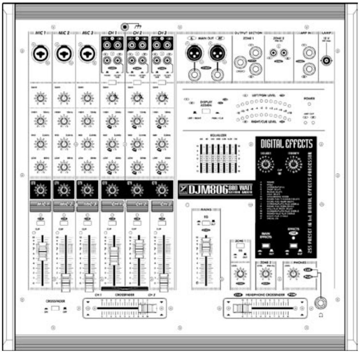
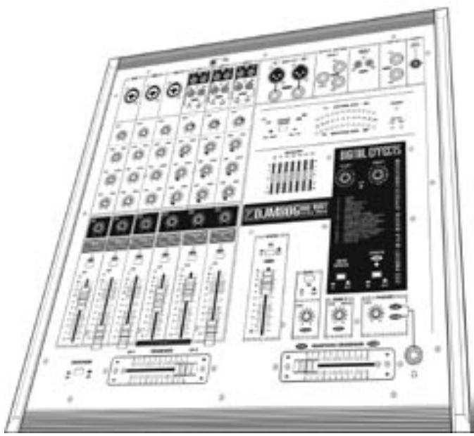
Your new DJM806 Mixer/Amplifier is designed and built to provide long-term trouble free performance. Drawing on thirty-five years of experience in the design and manufacturing of powered mixing consoles, Yorkville engineers were able to optimize the design of the first high-powered DJ mixer. Features include rack mountability, quiet internal fan cooling, three microphone input-channels, three stereo input channels with dual, switch-selectable pairs of inputs, removable interchangeable main crossfader and headphone crossfader, two zones out, stereo balanced line outputs, headphone monitoring of both the cue and program buses, switchable stereo 7-band EQ, level display assignable to Left/Right stereo operation or cue/program operation, 255-preset digital signal processing, 800 watts of stereo power built-in, a selection of 1/4-inch and Speakon™ output connectors.
Terminology
- 3-pin microphone inputs are referred to as XLR connectors.
- 1/4 -inch jack sockets are called phone connectors.
- Balanced 1/4 -inch inputs or outputs are called TRS or Tip-Ring-Sleeve
- Master control and mixing channels are called buses.
- Overload indicators are called CLIP LED's.
- Patch cables with dual conductors plus shielding and Tip-Ring-Sleeve (stereo) 1/4 -inch phone plugs are referred to as balanced patch cables.
Basic Features
- Channels 1-3 Balanced XLR & 1/4 -inch Combination Jack
- Balanced Mic inputs with low-noise input circuit design.
- Stereo Channels have Switchable Phono/Line stereo inputs
- Three-band EQ with +15dB/-15dB of range for Mic Channels.
- Three-band EQ with +15dB/-20dB of range for Stereo Channels.
Post-EQ, post-fader, EFX (effects) send controls. - Increased circuit headroom and gain for a more flexible mix.
- Gold internal bus-interconnects for long life and maximum signal integrity.
- Cue buttons and LEDs on all channels
- Pulse-stretching Clip LED's indicate even the briefest peaks and fire at -3dB, well before the onset of actual clipping, at all active channel stages.

Feature Details
Mic Channels (MIC 1, MIC 2, MIC 3)
Inputs
Each mic channel is mono and has a combination XLR/1/4-inch TRS (balanced) microphone connector. The XLR segment is optimized for low-impedance microphones and is wired Pin 1 = Ground, Pin 2 = in phase and Pin 3 = reverse phase. It will accept line-level signals, however the GAIN control will need to be turned to a lower setting to prevent clipping. The 1/4-inch Tip-Ring-Sleeve wiring is; Tip=in phase, Ring=reverse phase and Sleeve=Ground.
Gain Control
With signal applied to the input, adjust this control so that occasional flashes of the Clip LED are observed — alternately, you can Cue the channel and adjust for "0" on the Level Meter. This will ensure that the signal level fits comfortably within the channel strip's headroom ~ low enough to prevent distortion, and yet high enough to preserve the signal-to-noise ratio.
High, Mid, Low Channel EQ
The High, Mid, and Low equalization is variable by +/-15dB. This is a considerable amount of gain change, roughly equivalent to a 150% variation in audible loudness.
EFX Send Control
The EFX send control varies the amount of post-EQ, post-fader channel signal sent to the master EFX bus. The output of the EFX bus then goes to the internal 16-bit processor. The output of the effects processor then goes to the Main master section to be mixed with the signals going there direct from the input channels.
Cue Button
The Cue feature enables you to preview channel signals via headphones before they go to the main system. The Cue signal is post-EQ so that the channel equalization will be in effect through the headphones, it is pre-fader so that you may use the Right/Cue Level meter to help set the channel Gain for an average "0" reading. Use the Phones Level to adjust cueing volume. Cue LED's remain on while the cue buttons are depressed.
To test the Cue feature, simply follow these steps:
a) Connect a low, or high, impedance mic to Mic 1, 2, or 3 and set the channel fader to zero.
b) With the Headphones Crossfader set to Cue, phones plugged in, the Phone Level turned up and the Display Assign button down in Pgm/Cue position, you are ready to preview the mic.
c) Depress the channel Cue button. Now that channel will have prominence through your headphones.
d) Talk through the mic at performance volume. Listen through the phones while adjusting the channel Gain for maximum signal level before Clip activity on the channel or for roughly a “0” average reading on the meters.
e) When you are ready to insert the program, simply take it off hold and bring up the channel level fader. If it is on Channel 1 or Channel 2, you will also need to Crossfade to it.
Channel Fader
This adjusts the level of the post-EQ channel signal headed directly for the Left and Right Main masters. It also regulates the EFX send signal level.
Clip LED
The channel Clip LED watches all the active electronic stages in the channel circuit. Whenever any stage's signal peak approaches clipping to within 3dB, the Clip LED circuitry captures and displays this event. See under Gain control for more about this feature.
Stereo Channel Inputs (CH1, CH2, CH3)
Inputs & Selector Buttons
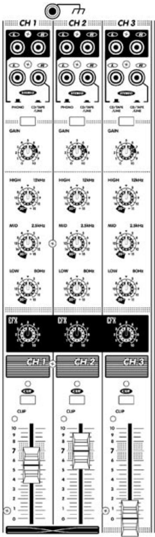
The DJM806 features internal RIAA phono equalizers on Channels 1 and 2. Those channels will directly accept the output from turntables with the channel input selector up in the Phono position. There are also CD/TAPE/LINE inputs on all three-program channels, which may be activated with the input selectors. This way, you can connect up to six different sources via these three channels and punch them in as desired.
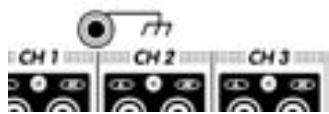
Ground Terminal
Connect turntable ground wire here to minimize hum and noise.
Gain Control
With signal applied to the input, adjust the GAIN so that occasional flashes of the CLIP LED are observed — alternately, you can CUE the channel and adjust for "0" on the Level Meter. This will ensure that the signal level fits comfortably within the channel strip's headroom ~ low enough to prevent distortion, and yet high enough to preserve the signal to noise ratio.
High, Mid, Low Channel EQ
Equalization is varied by three controls labeled High, Mid and Low. Each control can either boost the amplitude of its frequency band by +15dB or cut by -20dB . The -20dB cut capability is especially helpful when you are cueing and crossfading cuts of dissimilar tempo and don't want the bass beats to conflict. You turn the channel's LO EQ to -20dB before crossfading to it, and then simply turn it back up while completing the crossfade.
Effects Send Control
The EFX send control varies the amount of post-EQ, post-fader channel signal sent internally to the master DIGITAL EFFECTS system's 16-bit processor. The output of the effects processor then goes to the MAINS master section to be mixed with the dry signals going there direct from the input channels. Remember, because this send is post-fader, the channel fader must be pushed up for EFX signal to get to the effects processor.
Cue Button & LED
The CUE feature enables you to preview channel signals via headphones before they go to the main system. The CUE signal is post-EQ so that the channel equalization will be in effect through the headphones, and it is pre-fader so that you may use the Right/Cue Level meter to help set the channel Gain for an average “0” reading. Use the Phones Level to adjust cueing volume. Cue LED’s remain on while the cue buttons are depressed.
To test the Cue feature, simply follow these steps:
a) Connect a signal source (tape deck, CD player or turntable) to CH1, 2 or 3 and set the channel fader to zero. With the Headphones Crossfader set to Cue, phones plugged in, the Phones Level turned up and the Display Assign button down in Pgm/Cue position, you are ready to preview the program.
b) Depress the channel Cue button. Now that channel will have prominence through your headphones.
c) Listen through the phones while adjusting the channel Gain for
maximum signal level before Clip activity on the channel, or for roughly a "0" average reading on the meter. Also adjust the channel EQ as desired, then put the program on hold awaiting insertion and take the channel off Cue.
d) When you are ready to insert the program, simply bring up the channel level.
e) When you are ready to insert the recorded material, simply punch the Cue button into the up position, then take the recorded material off play hold/pause and bring up the channel fader to the desired mix levels.
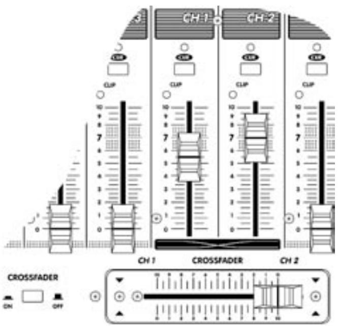
Channel Fader
This adjusts the levels of both the post-channel-EQ signal headed directly for the Mains master and the EFX send signal headed for the effects processor. The shaded area of the fader indications around "7" are roughly in the slide range where movements produce the smallest, most precise amounts of level change. Above and below that area, changes occur more quickly to provide fast "max" or "off" settings.
Channel Clip LED
The channel Clip LED watches all the active electronic stages in the channel circuit. Whenever any stage's signal peak approaches clipping to within 3dB, the Clip LED circuitry captures and displays this event. See under Gain control for more about this feature.
Channel Crossfader
The Crossfader selects between Channels 1 and 2 sending them to the MAIN master. This much-used fader is removable for service and is interchangeable with the Headphone Crossfader in an emergency.
Channel Crossfader On/Off Button
This pushbutton allows you to turn the Crossfader off while replacing the Crossfader, or you may prefer to disable the Crossfader and use the channel faders for mixing.
Master Features
IMPORTANT!
The mixer section of the DJM806 will remain operational if the built-in power amp ever shuts down. The Main outputs would be used to connect another power amp in this instance.
Master Fader
The Master Fader determines the Main system's level along with the channel faders. Leave at a low setting when playing quietly to reduce bus noise, and for mixing convenience.
Main Out Connectors
These balanced XLR and 14 -inch TRS (Tip-Ring-Sleeve) line-level outputs reflect the post-EQ, post-effects final mix signal as regulated by the Mains master fader. Connect external amplifiers here for main system reinforcement. Alternately you may use these connectors to patch a stereo crossover/processor (e.g. elite) or a compressor/limiter between the DJM806's mixer section and built-in power amp. See under Amp In Jacks for patching instructions You may use balanced or unbalanced patch cables, however for quietest operation we recommend balanced cables.
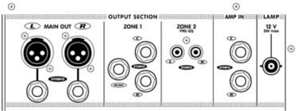
Zone Output Section
Located in the upper right area, beside the Mains Output jacks, are the Zone 1 and Zone 2 line-level Outputs. These are Tip-Ring-Sleeve (balanced) 14 -inch connectors, which will accept unbalanced patch cords (but we recommend you use balanced cables for quietest performance). They are included for supplying signal to external power amplifiers or powered speakers, another mixer, triggered lights, etc. Each Zone has its own master Level control.
Zone 1 has Left and Right outputs for driving a stereo amp/speaker setup, as well as a Mono output for driving a powered subwoofer or triggered lighting. The Zone 1 signals go through the 7-band graphic equalizer via the Zone 1 EQ In/Out pushbutton. With the In/Out feature, Zone 1 can bypass the onboard EQ if you are using it to run a separate amp/speaker system with different sound characteristics than the main speakers, perhaps near-field powered monitors.
Zone 2 is pre-EQ - i.e. it does not go through the graphic. It may be used for connection to a tape deck, a second mixer or another amp/speaker system.
7-Band Graphic Equalizer & In/Out Button
The stereo, graphic equalizer can be switched In or Out of the Main signal with the bypass button located just above the Mains fader. Since there is up to +/-12dB of cut/boost, you can use the EQ for controlling feedback quite effectively.
Digital Effects Processor - General
The internal Digital Effects Processor is a full 16-bit, 20kHz bandwidth DSP-based effects subsystem developed by Applied Research & Technology in Rochester, New York. It has been custom programmed with 255 effects ranging from reverb to echo and special effects. The selection of effects was determined in collaboration with a panel of sound engineers experienced in live performance mixing. As a result you should find the internal effects system to be more than adequate for most applications.
Main Effects In/Out Button
The In/Out button allows you to switch the preset effects on or off. You might, for example, choose to have a particular special effect on your voice at certain times. The In/Out button would let you punch it in and out as required.
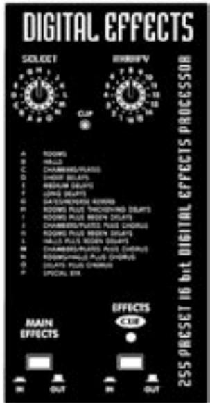
Digital Effects Clip LED
The Clip LED helps you to set up channel EFX send levels for optimum signal strength to drive the effects processor. With signals going into the channels requiring effects,
and with their level faders pushed up half-way or farther (remember, the EFX sends are post-fader), simply increase the EFX send control levels on those channels until some Digital Effects Clip LED activity is observed. Then turn EFX send levels down slightly until the flashing stops.
Effects Cue Button & LED
This feature allows you to preview effects via headphones. First, depress the Cue button - the LED will illuminate to indicate CUE "on". Now, with the desired channel's EFX send controls turned up roughly half-way, the Headphone Crossfader set to Cue and the Phones level control turned up, Select and Modify the desired effect. To add that effect to your main program mix, press the Cue button again (Cue LED goes off) and slide the Headphone Crossfader from Cue to Pgm.
Phones Jack, Level Control & Sources
The Phones jack accepts standard stereo headphones. The Phones level control and Phones jack are located in the lower right area of the control panel. The sources for all headache signals are the Mains (or Pgm) and Cue buses.
Level Displays & Display Assign Button
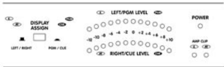
These displays follow either the Left and Right stereo main mix activities or Cue (anything on Cue) and Pgm (a mono mix of the main program), as selected by the Display Assign button. If either or both of the red Clip lights at the right end of the level display is flashing too much of the time in L/R mode, lower the Mains master level to avoid possible distortion on peaks.
L & R Amp In Jacks
These are switching jacks, which enable you to directly access either or both channels of the built-in power amplifier while disconnecting them from their normal internal functions. This permits you to insert an external EQ, a processor /crossover (e.g. élite) or a compressor/limiter between the mixer section's Main Outputs and the Amp In jacks. This in-series patch provides the 100% signal processing essential for these functions to work properly.
Power Amplifier
Power Amplifier Features
- A total output of 800 watts with well-proven, reliable Audiopro technology.
- Industry leading specifications for distortion, damping, and efficiency.
- Comprehensive protection against low or even shorted loads, overheating and DC damage to speakers.
- A combination of standard 1/4 -inch and high-current Speakon™ output connectors.
Power Amplifier - General
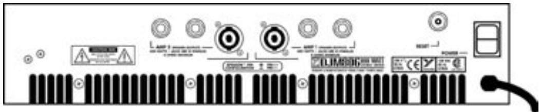
The DJM806 has an 800 watt stereo power amplifier. Each channel has an input sensitivity of +4dBv (1.4 volts RMS) for full power output and can deliver over 400 watts into a 4-ohm speaker load. The amplifier incorporates computer designed internal heatsinks and a variable-speed fan which automatically provides quiet operation consistent with cooling requirements. Cool air is drawn into the front of the mixer, and heated air is expelled along the bottom of the back. Even at maximum power, this arrangement results in quiet, dependable performance.
NOTE: Maintain clear air vents at the front and bottom rear of the mixer. They are essential for proper operation. Blocking the free flow of air through the mixer will result in system shutdown due to overheating. After the DJM806 cools down, operation will be restored. This should never happen if adequate ventilation is provided. Please keep the vents free pf obstructions.
Amp Clip LED's
Located on the right side of the control panel below the Power LED, the Amp Clip indicators flash when one or both channels of the built-in power amp are running out of headroom. Reduce the Mains fader level if Amp Clip activity becomes constant. Clipping distortion can damage speakers.
Speaker Connections
Two 14 -inch jacks and one Speakon™ connector are in parallel with each amp-channel output stage. This allows the use of speaker cables equipped with either type of connector. For full-power applications we recommend 14-gauge cables equipped with the Speakon™ connectors. This will reduce risk of resistance buildup. The Speakon™ system, developed in recent years by Neutrik in Switzerland, features block-style contacts capable of handling large amounts of power and the connectors lock down to prevent accidental kick-outs.
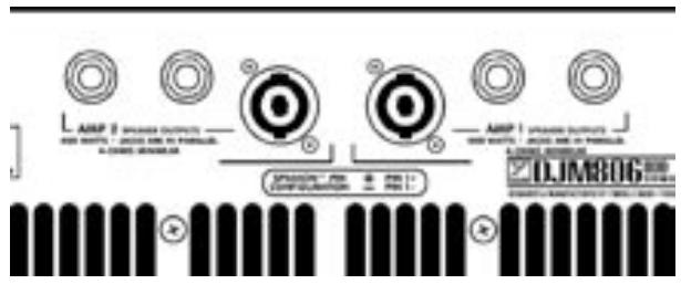
Connect one or two 8-ohm speakers or one (only) 4-ohm speaker to each channel. When connecting the Speakon's™, push them in firmly. Push the tab and pull to disconnect.
User tip: To connect two (8-ohm) speakers to one or both of the DJM806's powered output channels via the Speakon™ connectors, run a single Speakon™ -equipped cable, e.g. Yorkville model SP2-25SS or SP2-50SS with Speakons™ at both ends (most higher-powered speaker enclosures now feature Speakons™ as well) from the DJM806 to one of the enclosures. Now run a second cable from one cabinet to the next via their dual, parallel inputs.
Power Amplifier Protection
The DJM806's power amplifier is protected from damage due to open, shorted or excessively low speaker loads. It will continue to run into a low, less than 4-ohms, overall speaker impedance or even a total short-circuit for a brief time, however the amplifier's defense system will be activated. First, the built-in limiter will reduce output power levels and the fan speed may increase. Then, if the condition worsens, a thermal protection circuit will shut the power amplifier down. When this happens, check your system for restricted air intake/exhaust at the DJM806. Also check for shorted cables or connectors and/or reduce the number of speakers being driven. In a few minutes when it has had a chance to cool down, power amp function will resume.
User tip:
a) If the power amplifier shuts down as above, the mixer section will continue to function. This means that, if the DJM806's power amp fails to come back on (unlikely) and you have a spare power amplifier available, you can connect it to the DJM806 via the Main Out connectors.
b) Because the amplifier is also protected against open-circuit conditions, you may use the DJM806 without any speakers connected, for example if you wanted to do some recording.
The DJM806 power amplifier also features speaker protection in case of DC-offset. This is a very unlikely occurrence given the amp's inherently stable design, but should it happen, the output power is instantly shorted to ground and the speakers will be protected. The AC mains breaker on the back panel will blow in response to this condition (among others). If your breaker open more than once in a short space of time and the problem does not appear to be AC overload (see below), switch the power off and take your DJM806 to a Yorkville dealer for service.
AC Power Circuit-Breaker
Located on the back panel near the Speaker connectors, this circuit-breaker's (reset) main function is to shut the DJM806 down completely in case of an AC power overload. If, for example, the unit were accidentally connected to a high-voltage power outlet, this breaker would open as soon as the DJM806 Power switch was flipped on. If this breaker opens immediately, try plugging the DJM806 into another power outlet. Also, see above regarding DC-offset speaker protection.
Rack Mounting
To rack-mount the DJM806 you will need to purchase the accessory RK812 rack ears. Then, simply remove the three screws holding each of the DJM806's two end moldings in place and use the screws to mount the rack ears to the sides of the mixer.
General Operating Instructions
- Connect the AC power cord to a 120Volt AC grounded power outlet (220 to 240 Volts in export units).
- Switch on the Power and turn the Main and Monitor Master controls to Off for now.
- Connect low, or high impedance microphones to either the 3-pin XLR or 1/4 -inch segments of the Mic1, 2, and/or 3 inputs.
- Connect stereo sources to Channels 1, 2, and 3 with RCA-ended patch cords. Now set the input selector buttons for the inputs you are using.
- Using heavy-gauge speaker cables (see under Speaker Connections) connect one 4-ohm, or two 8-ohm speakers to each channel on the back panel.
- During a sound check, set the Mains master at "7" (a good getting-started setting) then adjust the channel Gain and EQ controls, also the level faders as required for the right basic mix and sound level. See under Gain Control and Cue Button for tips on setting the Gain.
- Still during the sound check, connect your headphones to the Phones jack and turn up the Phones level. Now you are ready to listen to the main mix or check out Cue'd channels or effects (see under the Channel Cue and Effects Cue sections).
- Turn up the EFX send controls on those channels you wish to have effects (see under Effects Clip LED for more on this). Now you can kill the effects sound through the main speakers by punching the Main Effects button into the "up" position, then listen to the effects through the headphones by sliding the Headphone Crossfader to Cue and depressing the Effects Cue button (the LED will come on). Now Select and Modify the effects via those controls then punch in the Main Effects button when you wish to insert effects into the main program.
- Adjust the graphic EQ as required. Always use an EQ sparingly. Remember, exaggerated EQ settings cost you power headroom and clarity when the volume gets pumped.
Specifications
Number of Channels 6
Mono Channel EQ
Stereo Channel EQ
Channel Effects Yes
Monitors Effects N/A
Crossfader (Function / Length) Channel Fader - 60mm,Cue Fader- 60mm
Inputs - 1/4" / XLR Combi 3, Mic 1/2/3
Inputs - RCA (unbal)
Mute Switches
Line / Phono Level Switches
Clip /Mute LED All Channels, Effects Section, Amp
VU Meter 12 LED with Floating Peak Switchable (Main/Cue)
Headphone Monitor Features Yes (Switchable)
Internal Effects Digital 16 Bit; 255 Effects
Effects Send 1 Internal
Effects Return to Main Yes
Effects Return to Monitor N/A
Record Outputs Zone
Max Gain to Line Out -Mic Input (dB)
Max Gain to Line Out -Line Input (dB)
Master EQ -1 (type /Channels /Range - dB)
Main Outputs (Line Level)
Main Amp Inputs (Line Level)
Outputs - Amp A - 1/4-inch Jack
Outputs - Amp A - Speakon 4-p
Outputs - Amp B - 1/4-inch Jack
Outputs - Amp B - Speakon 4-psi
Mixer - Signal to Noise Ratio (dB) 100
Iter - Frequency Response (Tone and EQ Flat, +/-2dB) 20 Hz - 20,000 Hz
- Input Referred Noise to line out, @ 150 ohms (dBv)
Mixer THD (Main out w/ -10dB input)
Amp A - Power Output @ 8 ohms (0%1"THD, 1kHz)
Amp A - Power Output @ 4 ohms 400
Amp B - Power Output @ 8 Ohms (0%1"THD, 1kHz)
Amp B - Power Output @ 4 ohms
THD-1kHz(dB) less
THD - 20Hz-20kHz (dB)
Hum and Noise (un / Aweight -dB)
Typical crosstalk -1 kHz (dB)
Input Impedance - Bal/Unbal (ohms)
Input Sensitivity (Vrms Sine)
CMRR @ 60Hz (min/typ)
Max Votage Gain (dB)
Power Consumption (typ/max)
Protection Thermal / Load / DC
Cooling Variable Speed DC Fan
Transformer Type Toroidal
Finish Scratch Resistant Vinyl-Coated Aluminum Top
Chassis Construction Heavy Gauge Metal
Rackmount Yes (RK812)
or 12V DC (BNC) Yes.
Other Features Zone 1 pre/post EQ. Zone 2 pre EQ.
s (DWH. inches) 18 × 19 × 5.5
Dimensions (DWH, cm) 45.7 × 48.3 × 14
Weight (Ibs/kg) 38/17.3
Introduction
2x XLR, 2x 1/4-pouce PBM
2x 1/4 pouces (PBM)
2
1
2
1
100
20 Hz - 20,000 Hz
-117
Moins que 0.05%
240
400
240
400
Moins que 0.03%
Yorkville's two and ten-year unlimited warranty on this product is transferable and does not require registration with Yorkville Sound or your dealer. If this product should fail for any reason within two years of the original purchase date (ten years for the wooden enclosure), simply return it to your Yorkville dealer with original proof of purchase and it will be repaired free of charge. This includes all Yorkville products, except for the YSM Series studio monitors, Coliseum Mini Series and TX Series Loudspeakers.
Freight charges, consequential damages, weather damage, damage as a result of improper installation, damages due to exposure to extreme humidity, accident or natural disaster are excluded under the terms of this warranty. Warranty does not cover consumables such as vacuum tubes or par bulbs. See your Yorkville dealer for more details. Warranty valid only in Canada and the United States.
Garantie Illimitée
Voice: (716) 297-2920
Fax: (716) 297-3689

Yorkville Sound 550 Granite Court Pickering, Ontario 1W-3Y8 CANADA
Yorkville Sound Inc.
4625 Witmer Industrial Estate
Niagara Falls, New York
14305 USA

WEB: www.yorkville.com
Voice: (716) 297-2920
Fax: (716) 297-3689