USER MANUAL MP8DX YORKVILLE
IMPORTANT SAFETY INSTRUCTIONS
CAUTION AVIS
RISK OF ELECTRIC SHOCK
DO NOT OPEN
RISQUE DE CHOC ELECTRIQUE
NE PAS OUVRIR

INSTRUCTIONS PERTAINING TO A RISK OF FIRE, ELECTRIC SHOCK, OR INJURY TO PERSONS.
CAUTION:
TO REDUCE THE RISK OF ELECTRIC SHOCK, DO
NOT REMOVE COVER (OR BACK).
NO USER SERVICEABLE PARTS INSIDE.
REFER SERVICING TO QUALIFIED
SERVICE PERSONNEL.
INSTRUCTIONS RELATIVES AU RISQUE DE FEU, CHOC ÉLECTRIQUE, OU BLESSURES AUX PERSONNES.
AVIS:
AFIN DE REDUIRE LES RISQUE DE CHOC ELECTRIQUE,
N'ENLEVEZ PAS LE COUVERT (OU LE PANNEAU
ARRIERE). NE CONTIENT AUCUNE PIECE REPARABLE
PAR L'UTILISATEUR.
CONSULTEZ UN TECHNICIEN QUALIFIE
POUR L'ENTRETIENT.
Read Instructions:
The Owner's Manual should be read and understood before operation of your unit. Please, save these instructions for future reference.
Packaging:
Keep the box and packaging materials, in case the unit needs to be returned for service.
Warning:
When using electric products, basic precautions should always be followed, including the following:
Power Sources:
Your unit should be connected to a power source only of the voltage specified in the owners manual or as marked on the unit.
This unit has a polarized plug. Do not use with an extension cord or receptacle unless the plug can be fully inserted. Precautions should be taken so that the grounding scheme on the unit is not defeated.
Hazards:
Do not place this product on an unstable cart, stand, tripod, bracket or table. The product may fall, causing serious personal injury and serious damage to the product. Use only with cart, stand, tripod, bracket, or table recommended by the manufacturer or sold with the product. Follow the manufacturer's instructions when installing the product and use mounting accessories recommended by the manufacturer.
The apparatus should not be exposed to dripping or splashing water; no objects filled with liquids should be placed on the apparatus.
Terminals marked with the "lightning bolt" are hazardous live; the external wiring connected to these terminals require installation by an instructed person or the use of ready made leads or cords.
No naked flame sources, such as lighted candles, should be placed on the apparatus.
Power Cord:
The AC supply cord should be routed so that it is unlikely that it will be damaged. If the AC supply cord is damaged DO NOT
OPERATE THE UNIT.
Service:
The unit should be serviced only by qualified service personnel.
We have coupled our extensive experience in the development and production of powered mixers, (with state of the art, computer assisted design technology) to create the smallest, lightest, and most powerful combination mixer/amplifiers available. We at Yorkville Sound are confident that you will find your new MP8dx to be an efficient and versatile solution to your mixer needs. This manual contains information to help you get the maximum performance from your MP8dx. We hope you'll take the time to read it.
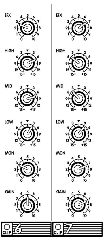
The MP8dx features standard XLR type Low-impedance MIC IN connectors on all channels. These microphone inputs are electronically balanced for maximum noise suppression and have characteristics matching all low impedance dynamic microphones. Condenser microphones may also be connected with 24 Volt DC phantom power activated via the back-panel PHANTOM push-button. (Note: condenser and dynamic mics may be used together with the PHANTOM power activated. It will not affect the performance of the dynamic mics). Additionally, there are high-impedance 1/4'' BAL LINE IN jacks on channels 1 through 6. These are electronically balanced line-level inputs, but will accept either balanced or unbalanced input cables from high impedance microphones, guitars, amplifier Line outputs, synthesizers, electric pianos, etc. (Note: when connecting a balanced signal, employ balanced patch cables with a ring/tip/sleeve (stereo) 1/4'' plug on the mixer end). Channels 7 and 8 have dual TAPE/CD/LINE IN RCA type inputs. Either the XLR or RCA type inputs (not both) may be used to connect a tape deck, CD player or an outboard mixer to these channels (using both RCA jacks is OK). A phono preamplifier must be connected to the MP8dx inputs for optimum turntable performance.
- Do not connect signals to both types of inputs on any one channel (e.g. the MIC and LINE IN's on channels 1 to 6 or the XLR and RCA type TAPE/CD/LINE IN's on channels 7 and 8). To do so will cause improper operation of the input circuit. (Note: you may connect a stereo source to channels 1 through 6 but you must use two channels, one for left and one for right).
2. CHANNEL GAIN CONTROLS & CLIP LEDs
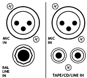
The GAIN control has a range of 40dB. This adjustment determines both the input sensitivity of the channel and the signal level sent to the MAIN mixing bus. (The MP80x channel circuitry does not require separate gain and level controls). The CLIP LED is set to illuminate when the channel's overall signal level is 3dB below the onset of actual clipping distortion. As a result, small amounts of LED activity are acceptable, however frequent or continuous activity indicates the need to turn down the GAIN control.
3. CHANNEL LOW, MID, & HIGH EQUALIZATION
The MP8dx's LOW, MID & HIGH EQ controls independently adjust the bass, middle and treble frequencies for each channel. Center frequencies have been carefully selected for optimum sonic adjustments and the gain range for each control is plus or minus (+/-) 15dB to provide versatile equalization consistent with the clean
simplicity of the MP8DX' 's design. As with all equalizers, boosts at one or more frequencies increase the channel's signal level. If the channel is already at a fairly high operating level, this may cause clipping, in which case the CLIP LED will light. Reduce the GAIN setting and/or the EQ boosts if CLIP activity is excessive. (Note: center position reflects a neutral or flat EQ control setting, however lower EQ control settings may be effectively employed to reduce feedback and/or distortion).
4. CHANNEL MON CONTROL
Each channel has a MON (monitor send) control which varies the amount of channel signal being tapped off and sent to the monitor bus in the MP8dx. The MON signal is pre-fader and pre-channel EQ, in other words it is taken before the GAIN and EQ controls so that the monitor mix can be independent of the main mix. As a result, channel EQ settings do not affect the sound of the monitor signals, nor do the channel GAIN controls regulate their volume.
5. CHANNEL EFX CONTROL
Each channel has an EFX (effects send) control which adjusts the level of the channel signal being tapped off and sent to the MP8DX's effects bus. This signal is post-fader and post-EQ, in other words it is affected by both the channel EQ controls and the channel GAIN control. Normally, the output signal from the effects bus is internally routed to the DIGITAL EFFECTS PROCESSOR. In this situation, the EFX control would regulate the intensity of the built-in effects on that channel's sound through the main PA system and the RECORD OUT jacks. In standard operating mode with the built-in effects working, you can connect a regular on/off footswitch (e.g.
Yorkville model IFS-1A) to the EFX FOOTSWITCH/SEND jack to turn the internal effects on and off. See the section EFX FOOTSWITCH/SEND later in this manual for more information. Alternatively, this signal can be connected to the input of an external effects unit and returned via a channel. However, if you do not require any effects at all, the effects bus output signal can be connected to the input of an additional monitor system or other amp/speaker system via the EFX
FOOTSWITCH/SEND jack using a standard shielded patch cord. In this case, the EFX controls would act as send controls to achieve a semi-separate mix. (Remember that the channel GAIN controls will also affect this signal).
MASTER SECTION
1. MAIN MASTER CONTROL & CLIP LED
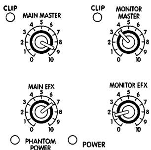
The MAIN MASTER control adjusts the overall level of the main mix and the PA volume. Beside this control is a CLIP LED, which indicates high signal levels within the main mixing bus. Reduce the MAIN MASTER, or the channel GAIN controls, if the MAIN CLIP LED is more than slightly active. (Note: to ensure maximum signal headroom and clarity, operate the mixer with the MAIN MASTER set at 7 or so. This way, you will be running the channel GAIN controls at lower settings, which helps to ensure that the channels do not clip).
2. MONITOR MASTER CONTROL
The overall level of the monitor mix is adjusted with the MONITOR MASTER control. Beside it is a CLIP LED, which indicates high signal levels within this bus. Reduce the MONITOR MASTER or the channel MON levels if the MONITOR CLIP LED is more than slightly active. (Note: as with the MAIN MASTER, keep the MASTER at a relatively high setting to ensure maximum clarity).
3. MAIN EFFECTS MASTER CONTROL
The MAIN EFX master control regulates the amount of signal going from the output of the internal DIGITAL EFFECTS PROCESSOR to the MAIN mixing bus where it is mixed with the dry signals direct from the channels. It controls overall effects intensity on the MAIN output signal and RECORD OUT signal as well as through the main PA speakers.



4. MONITOR EFFECTS MASTER CONTROL

The MONITOR EFX master control regulates the amount of signal going from the output of the internal DIGITAL EFFECTS PROCESSOR to the MONITOR mixing bus where it is mixed with the dry signals direct from the channel MON send controls. It controls overall effects intensity of the MONITOR LINE OUT signal.
5. MAIN LINE OUT & AMP A IN JACKS
These jacks can serve a variety of patching and routing purposes. The MAIN LINE OUT is positioned in the signal path after the MP8DX's main graphic equalizer and is therefore regulated by it (i.e. it is post-EQ).
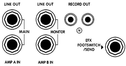
The main bus signals are available at line level (not speaker level, use the SPEAKER outputs on the back panel to drive speakers) from the MAIN LINE OUT jack. Taking a signal from this jack has no effect on the operation of the MP8dx's built-in power amplifier. It is therefore possible to feed an external power amplifier or even several,
interconnected power amps, with the MAIN output signal while the internal power amplifier is also functioning (although it is not necessary to have speakers connected - e.g. if you want to use the unit strictly as a mixer).
The AMP A IN jack is a direct input to the MAIN 400 Watt power amplifier, it is referred to as AMP A. An alternative use for the AMP A IN jack is as a patching input. Because this is a switching jack, when you plug into it, you interrupt the internal flow of the signal going from the output of the Main mixing bus to the input of the built-in 400 Watt power amp. This allows you to insert signal control devices such as an elite processor, an additional equalizer, or a compressor/limiter into the Main signal path. It is even possible to connect another mixer to the MP8px's power amplifiers via the AMP A IN jack. This slaves the amplifier to that mixer's signals (i.e. it no longer receives the built-in mixer's signals), which means that you could use the built-in mixer to do another, totally separate mixing job. For example, you could patch the MP8px's MAIN output to an input on another mixer connected to amps driving a PA speaker system while using the MP8px's internal A amp to power control room speakers.
6. MONITOR LINE OUT & AMP B IN JACKS
These jacks can serve a variety of patching and routing purposes. They are positioned in the signal path after the MP8 DX s monitor graphic equalizer.
The monitor mix signal is available at line level from the MONITOR LINE OUT jack at all times. Taking a signal from this jack has no effect upon the configuration of the MP8dx, so it is possible to feed an external power amplifier with the monitor mix signal while the internal power amplifier also amplifies the monitor mix signal. However, plugging into the MONITOR AMP B IN jack will break the internal monitor mix signal path. This allows you to insert a signal processing device (such as an elite processor or digital delay unit), into the monitor signal path of the MP8dx. To achieve this connect a cable from the MONITOR LINE OUT jack to the processor's input jack, and a cable from the processor's output jack to the MP8dx's MONITOR AMP B IN jack.
You can deliver an external signal to the monitor power amplifier of the MP8DX from any line level source via the AMP B IN jack. In this case you would route the MP8DX' s monitor mix from the MONITOR LINE OUT jack to another mixer, or to an external power amplifier.
To summarize, the MONITOR LINE OUT and MONITOR AMP B IN jacks may be used as a post-mix effects loop or a signal processing patch, the MONITOR LINE OUT jack can serve as a monitor mix output, and the MONITOR AMP B IN jack can be used as an auxiliary input to the internal 200 Watt power amplifier.
7. RECORD OUT JACKS
These phono connectors carry the pre-EQ (not affected by the MAIN EQ) main mix signals. RECORD OUT signal levels are regulated by the MAIN master. Using phonoto-phonopatch cords, connect the RECORD OUT jacks to the Aux. (line-level) inputs on the tape deck. Actual recording levels would now be adjusted using the tape deck's record level control/s.
Best results for recording will be achieved with the MAIN master and channel levels set fairly high. If you need to record while the MP8DX is operating in a PA situation and set at lower levels, perhaps in a church, you can have a technician make up two short **padded patch cables as specified below. These would be connected between the MAIN LINE OUT jack and the AMP A & jack. They will reduce the amount of signal going to the power amplifier inputs so that the MAIN master and channel levels can be set high enough to provide adequate RECORD OUT signal levels without the PA system being too loud.
** To fashion the -20dB padded patch cables, start with two short, shielded patch cords. On each cord, solder a 10k Ohm resistor in series with the tip of the plug to be inserted in a LINE OUT jack, then solder a 2.2k Ohm resistor across the plug to be inserted in an AMP IN jack. It would then be advisable to identify either the LINE OUT or AMP IN plugs on both cords perhaps with tape or a dab of paint on the plug jacket.
This jack may be used to connect a standard on/off footswitch for the internal DIGITAL EFFECTS PROCESSOR or alternately as an effects send jack to another effects processor. In this latter function, both the internal effects and the other devices would be sent signal. In that instance, you could connect the external unit's output to a LINE input on any channel. Here you would need to keep the GAIN level of that channel fairly low and make sure that its EFX control is turned off. As another alternative, the EFX FOOTSWITCH/SEND jack may be used to deliver line-level signal to the input of an auxiliary amp/speaker system or a tape deck.
9. POWER LED & THE SWITCH
The POWER LED lets you know that the MP8dx is plugged in and turned on. The AC power on/off switch is on the rear panel of the unit.
10. PHANTOM POWER
The PHANTOM power LED indicates that 24 volts of DC phantom power is present on all the XLR microphone inputs to power condenser microphones. Regular dynamic mics may be connected while the PHANTOM POWER is activated without encountering problems. The PHANTOM POWER push-button is located on the rear panel.
DIGITAL EFFECTS PROCESSOR
1. DIGITAL EFFECTS PROCESSOR SELECT & MODIFY CONTROLS
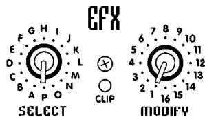
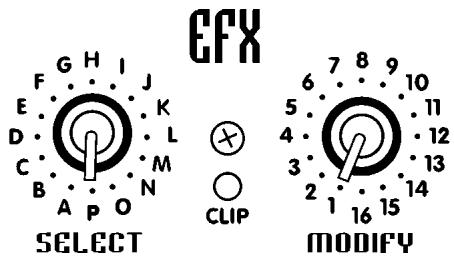
The SELECT control selects from 16 banks of reverb sounds, delays and other effects. Settings A through G represent single reverbs or echo delays. Settings H through P are combined or combo effects where two or more effects are blended together. Simply rotate the SELECT control to the basic type of effect you prefer. This is a continuous type of control so you may simply rotate it in either direction to reach the desired setting. Lists of effects banks appear in this manual and on the front panel of the MP8DX.
Each bank of effects contains 16 individual effect variations. The MODIFY control selects each one of these variations. For example, if bank E (Medium Delays), has been selected, position 1 will give you 200 milliseconds of delay, and positions 2 through 16 will give you progressively longer delays up to 375 milliseconds. Bank P is the exception to this rule. It consists of sixteen different special effects, such as pitch shift up, or down, detune flanger, etc.
2. EFFECTS CLIP LED
Situated between the SELECT and MODIFY controls, the CLIP LED indicates that the digital processor is receiving an input signal which is too strong, possibly resulting in distortion. For maximum dynamic range, the CLIP LED should flash briefly, but only on high-energy transients such as loud snare drum hits. If there is too much CLIP activity, turn down the channel EFX controls.
3. EFFECTS TABLES
- See the last page of this manual for the effect table.
SINGLE EFFECTS
A ROOMS
B HALLS
C CHAMBERS/PLATES
D SHORT DELAYS
E MEDIUM DELAYS
F LONG DELAYS
G GATES/REVERSE REVERB
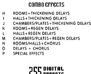
COMBO EFFECTS
H ROOMS+THICKENING DELAYS
HALLS+THICKENING DELAYS
J CHAMBERS/PLATES+THICKENING DELAYS
K ROOMS+REGEN DELAYS
L HALLS+REGEN DELAYS
M CHAMBERS/PLATES+REGEN DELAYS
N ROOMS/HALLS+CHORUS
O DELAYS + CHORUS
P SPECIAL EFFECTS
255 DIGITAL EFFECTS
BUILT IN GRAPHIC EQUALIZERS
General
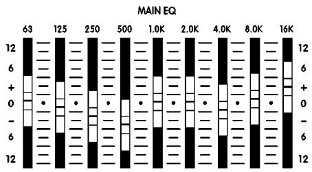
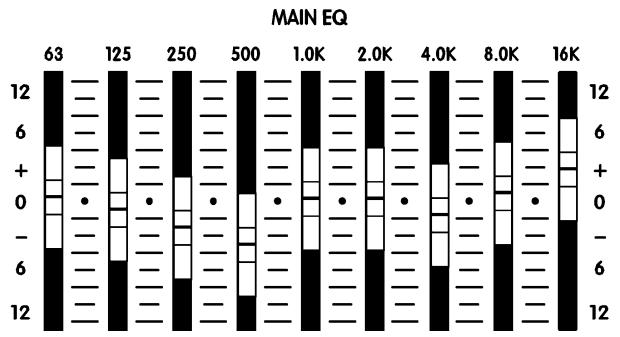
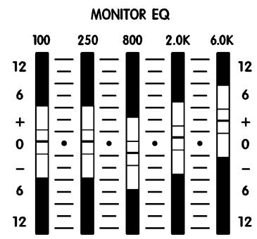
A graphic equalizer, represents a set of limited-range (+/-12dB) gain controls. In this case there are 9 sliders for the MAIN and 5 sliders for the MONITOR The MAIN EQ operates over a one-octave portion of the overall band of sound frequencies. Please note that equalizers can have an effect on the gain of the main and monitor system as well as its frequency response. Once adjusted, you may need to turn down the MAIN and/or MONITOR MASTER level/s if the CLIP LED/s beside them become very active.
There Are 3 Main Functions for the Graphic EQ
-
To adjust the system for feedback reduction, the normal technique is to turn the main or monitor system up to the point of feedback and move the EQ sliders, one at a time, to determine which frequency band is causing the feedback. (Remember to push them back up to center position if they don't stop the feedback). When isolated, the offending band is then pushed down about 3 to 6 dB. Usually only 2 or 3 bands can be reduced before the feedback elimination process begins to affect the sound quality.
-
To adjust for deficiencies in the main speaker system's bass response, the most common adjustment is to boost the 63Hz about 6 dB and the 125Hz about 3 dB. However, use of the graphic EQ to extend the deep bass frequency response of a speaker cabinet does use up a lot of the available system power, so this technique should be used with caution to avoid distortion and possible speaker damage. On the other hand, in applications where it is appropriate to sacrifice deep bass for higher overall sound output, the 63Hz slider should be taken down 6 dB below center. You may now increase the MAIN level for added volume.
-
Boosting low frequencies for the MONITOR mix is not recommended because it may interfere with the sound of the MAIN speakers.
-
The third use of the graphic equalizer is to adjust the sound character for artistic reasons. Each frequency is adjusted until the sound is what the musicians feel sounds best. The best sound system operators, however, usually strive to use a minimum of equalization for this purpose, or for boosting the bass. Instead, they use very minimal sound-shaping adjustments to ensure that the threat of feedback and distortion will also be minimal.
MP8x REAR PANEL
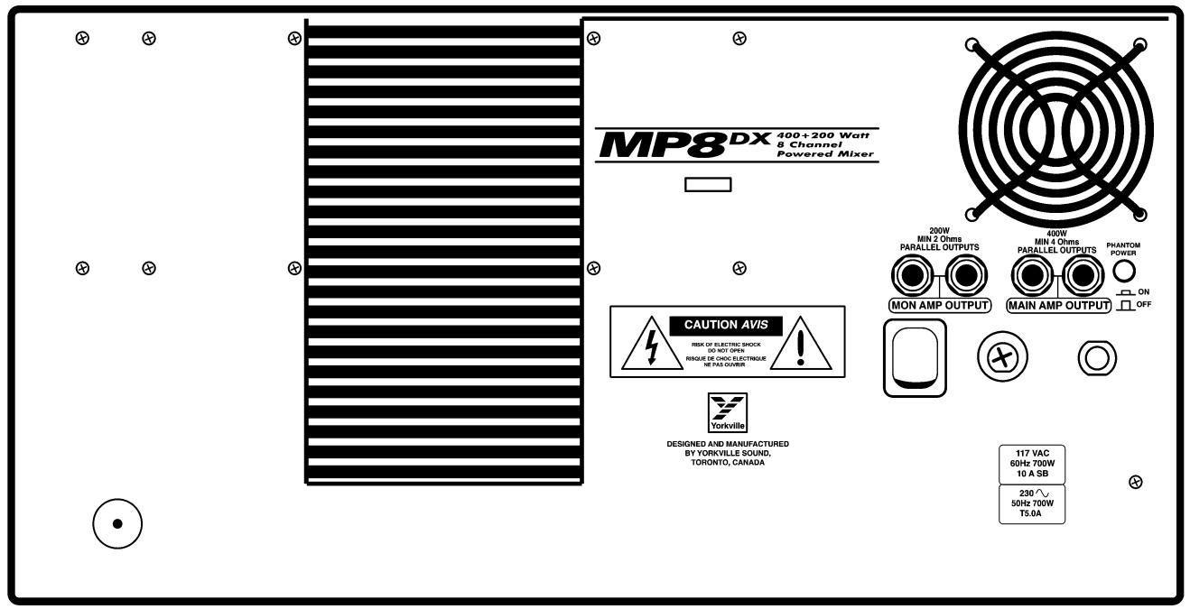
1. A & B SPEAKER OUTPUTS & HEATSINKS
Each of the MP8dx's power amplifiers have two 1/4" jacks for speaker connections. You may connect one 8-Ohm speaker cabinet to each jack (two speaker cabinets) or a single 4-Ohm speaker to AMP A. AMP B has a 2-Ohm minimum load rating and can therefore drive up to four 8-Ohm stage monitors, or two 4-Ohm stage monitors. Connecting two 8-Ohm speakers (i.e.a 4-Ohm load) to either AMP A or AMP B will not harm the MP8dx. If the amp overheats, the built-in thermal protection will cycle the amplifier on and off until it cools down, usually in a few minutes.
- Do not obstruct the flow of air around the heatsink fins on the rear of the MP8DX as this may cause the power amplifier to overheat and shut off. After the MP8DX cools down, operation will be restored automatically. This should never happen if adequate ventilation is provided at the back of the unit.
2. AC POWER SWITCH & FUSE
The power switch and fuse are located on the back panel. If you must replace the fuse, always replace it with the same type - a 12A slo-blo (T6A slo-blo in 220-240V export models). Do Not replace the fuse with the wrong type or wrap foil around the old one, as this may cause serious damage. If replaced fuses keep blowing, take the unit to your Yorkville dealer for service.
General Operating Instructions
- Connect the AC power cord to a 120 Volt AC grounded power outlet (220 to 240 Volts in export units).
- Turn the MAIN and MONITOR MASTER controls to 0 for now, then switch on the POWER.
- You can connect low-impedance microphones to the 3-pin XLR type MIC inputs.
- Connect high-impedance mics or mono line-level signal sources (i.e. amplifier line outputs, the output of a mono mixer, an electric instrument, etc.), to the 1/4n BAL LINE IN jacks on channels 1 to 6. Do not connect more than one signal source to any of these channels, that includes stereo outputs (if you try to connect a stereo source to a mono channel using a Y adapter, you may get distortion).
- Connect stereo sources (tape deck, CD player, stereo keyboard instrument, etc.) to channels 7 and/or 8 via the RCA (phono) type inputs. These signals will be summed into mono. Once again, connect only one signal source per channel, and use shielded patch cords for all pre-amp connections.
- Using 18-gauge, or heavier, speaker cables (never use shielded patch cords to connect speakers, they cannot handle the high current and will waste power by heating up), connect one or two 8-Ohm main PA speakers to the AMP A SPEAKER outputs on the back panel. If you have 4-Ohm speakers, you may connect only one. Connect 1 to 4 8-Ohm monitors, or up to two 4-Ohm monitors to the AMP B SPEAKER outputs.
a. If you are employing a separate power amplifier for the monitor speakers, run a shielded patch cord from the MONITOR LINE OUT jack to the input of the monitor power amp. If you are employing a separate graphic equalizer for the monitors run a shielded patch cord from the MONITOR LINE OUT jack to the input of the EQ. Then, another one from the EQ's output to the input of the monitor power amp.
- Position your main PA speakers at the front of the stage, pointing directly out at the audience. Position your monitor speakers on the stage floor, in front of the mic stands, pointing up at the backs of the mics. (Remember to use cardioid or uni-directional mics to reduce the threat of monitor feedback).
- During a sound check, with the band playing, or other sources feeding the mixer inputs, make the following control adjustments:
i. Set the channel LOW, MID, and HIGH EQ controls at center. Now, set the channel GAIN, MON, and EFX controls at 0 and the GRAPHIC EQ sliders at center position.
ii. Turn up the MAIN and MONITOR MASTER controls to approximately 8, the MAIN EFX master to around 7 and MONITOR EFX master to 5.
iii. Turn up the channel MON controls until the performers can hear themselves at adequate volume levels without feedback.
iv. Turn up the channel GAIN controls slowly until each channel can be heard at the desired volume level through the main PA speakers.
v. Turn up the EFX controls on those channels requiring effects. Usually this would be the lead and harmony vocal channels. Reverb may be used on other channels or on recorded music, but at low levels.
- Feedback during a performance is usually caused by one of the monitors. The main PA is less likely to feed back because the mics are so far away from the main PA speakers. Therefore, if you are using monitors and feedback occurs, try the following procedures:
i. Turn the MONITOR master down until the feedback stops.
ii. If you have a graphic equalizer patched between the MONITOR output and your monitor power amp, pull down one or two (but not more) of the EQ sliders in the frequency range where the sound seems to be occurring.
iii. Now turn the MONITOR master back up. If the feedback recurs, push the EQ slider/s back up to center position and try pulling down one or two others.
iv. In the rare case of main system feedback, follow the above type of procedure, but using the MAIN master and the built in GRAPHIC EQ.
FEATURES
MIXER
Balanced XLR inputs 8
Balanced 14'' inputs 6
Unbalanced RCA inputs 2 pairs
Channel Equalization High, Mid, and Low
Channel Effects Send Control YES
Channel Effects Post Channel EQ
Monitor Sends Pre-Gain
Digital Internal Effects 255 Presets
Main Out/Amp In YES (Mono) / YES
Monitor Out/Amp In YES/YES
Main EQ
Monitor EQ 5 Band, graphic
Effects Send/Footswitch YES
Effects to Main YES
Effects to Monitor YES
Record Out YES
Phantom Power 24 VDC
Dimensions (D/W/H) 10 × 21 × 11.85
(D/W/H) 25cm × 55cm × 30cm
Weight 38 lb. (17.5 kg.)
AMPLIFIERS
Rated Load Power
MAIN 400 Watts into 4 Ohms
MONITOR 200 Watts into 2 Ohms
Total Harmonic Distortion
<0.01%
Signal to Noise Ratio
MAIN 101 db, MONITOR 105 db
POWER REQUIREMENTS
North American
117 VAC 700 W VA 60 Hz
European
230 VAC 700 W VA 50 Hz
SPECIFICATIONS
MIXER SECTION
Input referred noise -122 dB
Max balanced input gain +59 dB
Balanced input impedance 1200 Ohms
Max balanced input gain 1 / 4'' jacks +40 dB
Balanced input impedance at 1/4" jacks 10k Ohms
Unbalanced input impedance at RCA 5k Ohms
Balanced CMRR min. 35dB, typical -50dB
Frequency response at 36 dB gain +/-3 dB, 20 Hz to 20 KHz
Signal path distortion less than 0.1% 20Hz-20KHz
Channel Clip LED threshold 3 dB before clipping
Channel EQ adjustment range +/- 15 dB
Graphic EQ adjustment range +/- 12 dB
Phantom Voltage 24 V
AMPLIFIERS
Frequency response +/-3 dB, 20 Hz to 20 KHz
Gain (MAIN) 29 dB
Gain (MONITOR) 24 dB
Input sensitivity 1.4 VRMS
Total Harmonic Distortion 0.05% at 1KHz
Amp A Max power into 4 Ohms <1% THD 400 Watts
Amp B Max power into 2 Ohms <1% THD 200 Watts
INTRODUCTION
PRINCIPAL 400 Watts, 4 Ohms
Distortion Harmonique Total
MONITEUR 200 Watts, 2 Ohms
Bourdonnement
<0.01%
PRINCIPAL 101 db, MONITEUR 105 db
PUISSANCE REQUIRE
Amérique du Nord
120 VAC 700 W VA 60 Hz
Europe
230 VAC 700 W VA 50 Hz
SPECIFICATIONS
MIXEUR
1 0.5s Bright Small Room
2 0.5s Warm Small Room
3 0.5s Dark Small Room
4 0.8s Bright Small Room
5 0.8s Warm Small Room
6 1.0s Bright Small Room
7 1.0s Warm Small Room
8 1.2s Bright Medium Room
9 1.2s Warm Medium Room
10 1.5s Bright Medium Room
1.1.5s Warm Medium Room
2 1.5s Dark Medium Room
3 2.0s Bright Large Room
4 2.0s Warm Large Room
5 2.5s Bright Large Room
6 2.5s Warm Large Room
B HALLS
1 1.5s Dark Medium Hall
2 1.5s Warm Medium Hall
3 1.5s Bright Medium Hall
4 2.0s Dark Medium Hall
5 2.0s Warm Medium Hall
6 2.0s Bright Medium Hal
7 2.5s Dark Medium Hall
8 2.5s Warm Medium Hall
9 2.5s Bright Medium Hall
0 3.5s Dark Medium Hall
1 3.5s Warm Medium Hall
2 3.5s Bright Medium Hal
3 5.0s Dark Large Hall
4 5.0s Warm Large Hall
5 8.0s Dark Huge Hall
6 8.0s Warm Huge Hall
C CHAMBERS PLATES
1 0.8s Warm Chamber
2 0.8s Bright Chamber
3 1.2s Warm Chamber
4 1.2s Bright Chamber
5 1.5s Warm Chamber
6 1.5s Bright Chamber
7 2.5s Warm Chamber
8 2.5s Bright Chamber
9 3.5s Warm Chamber
0 3.5s Bright Chamber
1 0.3s Bright Plate
2 0.5s Bright Plate
3 0.8s Bright Plate
4 1.2s Bright Plate
5 1.5s Bright Plate
6 2.0s Bright Plate
D SHORT DELAYS
1 30ms slap delay
2 35ms slap delay
3 40ms slap delay
4 50ms slap delay
5 60ms slap delay
6 70ms slap delay
7 80ms slap delay
3 90ms slap delay
9 100ms slap delay
0 100ms regen delay
1 125ms low regen delay
2 125ms medium regen delay
3 150ms low regen delay
4 150ms medium regen delay
5 175ms low regen delay
6 175ms medium regen delay
E MEDIUM DELAYS
1 200ms low regen delay
2 200ms medium regen delay
3 225ms low regen delay
4 225ms medium regen delay
5 250ms low regen delay
6 250ms medium regen delay
7 275ms low regen delay
3 275ms medium regen delay
9 300ms low regen delay
0 300ms medium regen delay
1 325ms low regen delay
2 325ms medium regen delay
3 350ms low regen delay
4 350ms medium regen delay
6 375ms low regen delay
6 375ms medium regen delay
F LONG DELAYS
1 390ms low regen delay
2 390ms medium regen delay
3 400ms low regen delay
4 400ms medium regen delay
5 410ms low regen delay
6 410ms medium regen delay
7 420ms low regen delay
8 420ms medium regen delay
9 430ms low regen delay
0 430ms medium regen delay
1 450ms low regen delay
2 450ms medium regen delay
3 475ms low regen delay
4 475ms medium regen delay
6 500ms low regen delay. 3 500
500ms medium regen delay
G GATED/REVERSE REVERB
1 0.8s decay 100ms Gate
2 0.8s decay 200ms Gate
3 1.2s decay 100ms Gate
4 1.2s decay 200ms Gate
5 1.8s decay 150ms Gate
6 1.8s decay 200ms Gate
7 2.0s decay 300ms Gate
3 2.5s decay 150ms Gate
9 2.5s decay 250ms Gate
0 2.5s decay 400ms Gate
1 0.5s decay 100ms Reverse
2 0.5s decay 200ms Reverse
3 1.0s decay 100ms Reverse
4 1.0s decay 200ms Reverse
5 2.5s decay 250ms Reverse
6 4.0s decay 300ms Reverse
H ROOMS & THICKENING DELAYS
1 0.5s Bright Small Room
+ 50ms doubling delay
2 0.5s Warm Small Room
+40ms doubling delay
3 0.5s Dark Small Room
+40ms doubling delay
4 0.8s Bright Small Room
+ 60ms doubling delay
5 0.8s Warm Small Room
+ 50ms doubling delay
6 1.0s Bright Small Room
+70ms slap delay
7 1.0s Warm Small Room
+ 50ms doubling delay
8
1.2s Warm Medium Room
+50ms doubling delay
10 1.5s Bright Medium Room
+80ms slap delay
11 1.5s Warm Medium Room
+60ms doubling delay
12 1.5s Dark Medium Room
+70msslap delay
13 2.0s Bright Large Room
+80msslap delay
14 2.0s Warm Large Room
+60ms doubling delay
15 2.5s Bright Lrg Rm
+100msslap delay
16 2.5s Warm Large Room
+80msslap delay
I HALLS & THICKEN DELAYS
1 1.5s Dark Medium Hall
+50ms doubling delay
2 1.5s Warm Medium Hall
+70ms slap delay
3 1.5s Bright Medium Hall
+90ms slap delay
4 2.0s Dark Medium Hall
+90ms slap delay
5 2.0s Warm Medium Hall
+70ms slap delay
6 2.0s Bright Medium Hall
+ 50ms doubling delay
7 2.5s Dark Medium Hall
+70ms slap delay
8 2.5s Warm Medium Hall
+80msslap delay
9 2.5s Bright Medium Hall
+100ms slap dela
0 3.5s Dark Medium Hall
+80ms slap delay
1 3.5s Warm Medium Hall
+90ms slap delay
2 3.5s Bright Medium Hall
+100ms slap dela
3 5.0s Dark Large Hall
+ 80ms slap delay
J CHAMBERS/ PLATES & THICKENING DELAYS
1 0.8s Warm Chamber
+50ms doubling delay
2 0.8s Bright Chamber
+ 50ms doubling delay
3 1.2s Warm Chamber
+60ms doubling delay
4 1.2s Bright Chamber
+70ms slap delay
5.1.5sWarmChamber
+70ms slap delay
6.1.5s Bright Chamber
+80msslan delay
7 2.5s Warm Chamber
+80ms slap delay
8 2.5s Bright Chamber
+100ms slap delay
9 3.5s Warm Chamber
+90ms slap delay
0 3.5s Bright Chamber
+100ms slap delay
1 0.3s Bright Plate
+40ms doubling delay
2 0.5s Bright Plate
+50ms doubling delay
3 0.8s Bright Plate
+50ms doubling delay
4 1.2s Bright Plate
+80msslap delay
5 1.5s Bright Plate
+80ms slap delay
6 2.0s Bright Plate
+100msslap delay
K ROOMS & REGEN DELAYS
1 0.5s Bright Small Room
+200ms regen delay
2 0.5s Warm Small Room
+175ms regen delay
3 0.5s Dark Small Room
+150ms regen delay
4 0.8s Bright Small Room
+200ms regen delay
5 0.8s Warm Small Room
+150ms regen delay
6 1.0s Bright Small Room
+175ms regen delay
7 1.0s Warm Small Room
+125ms regen delay
8 1.2s Bright Medium Room
+150ms regen delay
9 1.2s Warm Medium Room
+200ms regen delay
10 1.5s Bright Medium Room
+200ms regen delay
1 1.5s Warm Medium Room
+175ms regendelay
2 1.5s Dark Medium Room
+ 150ms regen delay
3 2.0s Bright Large Room
+200ms regen delay
4 2.0s Warm Large Room
+125ms regen delay
5 2.5s Bright Large Room
+150ms regendelay
6 2.5s Bright Large Room
+200ms regen delay
4 1.2s Bright Chamber
+200ms regen delay
5 1.5s Warm Chamber
+150ms regen delay
6 1.5s Bright Chamber
+200ms regen delay
7 2.5s Warm Chamber
+175ms regen delay
8 2.5s Bright Chamber
+125ms regen delay
9 3.5s Warm Chamber
+200ms regen delay
10 3.5s Bright Chamber
+150msregendelay
11 0.3s Bright Plate
+125ms regen delay
12 0.5s Bright Plate+150ms regen delay
13 0.8s Bright Plate+200ms regen delay
14 1.2s Bright Plate+175ms regen delay
15 1.5s Bright Plate+150ms regen delay
16 2.0s Bright Plate+200ms regen delay
N ROOMS/HALLS &CHORUS
1 0.5s Bright Room + slow chorus
2 0.8s Warm Room + medium chorus
3 1.0s Bright Room + slow chorus
4 1.2s Warm Room + medium chorus
5 1.5s Bright Room + slow chorus
6 1.8s Warm Room + slow chorus
7 2.5s Bright Room + medium chorus
8 3.0s Warm Room + slow chorus
9 2.0s Bright Hall + slow chorus
0 2.5s Warm Hall + medium chorus
1 2.5s Bright Hall + slow chorus
2 3.0s Warm Hall + slow chorus
3 3.5s Warm Hall + slow chorus
4 3.5s Bright Hall + medium chorus
5 5.0s Warm Hall + slow chorus
6 8.0s Warm Hall + slow chorus
O DELAYS & CHORUS
1 50ms doubling delay + slow chorus
2 80ms slap delay + medium chorus
3 100ms slap delay + medium chorus
4 150ms regen delay + slow chorus
5 175ms regen delay + med chorus
6 200ms regen delay + slow chorus
7 225ms regen delay + med chorus
8 250ms regen delay + slow chorus
9 275ms regen delay + med chorus
0 300ms regen delay + slow chorus
1 325ms regen delay + med chorus
2 350ms regen delay + slow chorus
3 370ms regen delay + med chorus
4 80ms regen delay + slow chorus
5 390ms regen delay + med chorus
6 400ms regen delay + slow chorus
P SPECIAL EFX
1 Pitch Shift octave down
2 Pitch Shift octave up
3 Pitch Shift major 3rd up
4 Pitch Shift major 5th do
5 Dual Pitch Shift major 3rd & 5th up
6 Dual Pitch Shift oct up & oct down
7 Detune Flanger
8 Slow Flanger w/ medium
9 Slow Flanger w/ high regen
0 Medium Flanger w/ medium regen
1 Medium Flanger w/ high regen
2 250ms high regen delay
3 500ms medium regen dc
4 500ms high regen delay
5 Slow Flanger + Pitch Shift oct down
6 Slow Flanger+Pitch Shift octave up

Niagara Falls, New York
14305 USA
Voice: (716) 297-2920
Fax: (716) 297-3689

Quality and Innovation Since 1963
Printed in Canada