
PA500.4 - Audio Amplifier POLK AUDIO - Free user manual and instructions
Find the device manual for free PA500.4 POLK AUDIO in PDF.
| Product Type | 4-channel Class AB audio amplifier |
| RMS Power (4 Ohms) | 90 W x 4 (20 Hz - 20 kHz, ≤ 0.08% THD) |
| RMS Power (2 Ohms) | 125 W x 4 (≤ 0.15% THD) |
| Bridged Power (4 Ohms) | 250 W x 2 |
| Frequency Response | 20 Hz - 20 kHz |
| Signal-to-Noise Ratio | 98 dBA (ref. 1 W into 4 Ohms) |
| Channel Separation | 65 dB at 1 kHz |
| Damping Factor | >150 |
| Input Impedance | 20 kOhms |
| Input Sensitivity | 250 mV to 8 V |
| Crossover Filter | 2-way Butterworth 50-500 Hz, 12 dB/octave slope (HPF/LPF/Flat) |
| Subsonic Filter | Switchable 24 dB/octave (PA500.4 and PA1100.5 only) |
| Bass EQ | +8 dB switchable (centered at 40 Hz) |
| Remote Control | Subwoofer level (remote included) |
| Inputs/Outputs | Stereo RCA inputs (2 channels), RCA pass-through outputs, speaker terminals |
| Power Supply | 10-16 V DC, 2 x 40 A fuses |
| Min. Power Wire | Gauge #8 |
| Protection | Thermal, short circuit, DC offset, over/under voltage, reverse polarity |
| Dimensions (W x D x H) | Approx. 350 x 240 x 50 mm |
| Weight | Approx. 2.1 kg |
| Box Contents | Amplifier, wiring harness, remote control, telephone cable, spare fuse, screws/washers, manual |
| Warranty | 1 year (parts and labor), 2 years if installed by an authorized dealer |
Frequently Asked Questions - PA500.4 POLK AUDIO
User questions about PA500.4 POLK AUDIO
0 question about this device. Answer the ones you know or ask your own.
Ask a new question about this device
Download the instructions for your Audio Amplifier in PDF format for free! Find your manual PA500.4 - POLK AUDIO and take your electronic device back in hand. On this page are published all the documents necessary for the use of your device. PA500.4 by POLK AUDIO.
USER MANUAL PA500.4 POLK AUDIO
Polk Audio—A Passion for Sound
Please take a moment and read through this manual before you get started. Installing a car audio system is a serious project. If you have any doubts about your ability to execute any of the installation steps found in this manual, save yourself a lot of grief and contact your local authorized Polk Audio AutoSound dealer. He (or she) is a professional installer and ready to help you get the most for your autosound dollar.
More information—including audio how-to articles, FAQs, and online manuals—is available on our award-winning website www.polkaudio.com/car. And if you ever have a question or comment, please feel free to call us or email us. In North America and Canada, call Polk Audio Customer Service 800-377-7655 (M-F, 9-6 EST) or via email polkcs@polkaudio.com. Outside the US, call 410-358-3600. We love to hear from you!
Here at Polk Audio, building loudspeakers and audio equipment is more than just our business—it's our passion. We're happy to share it with you.
Sincerely,

Matthew S. Polk
Co-Founder
FRANÇAIS
High-powered car audio systems may produce sound pressure levels that exceed the threshold at which hearing loss may result.
They may also impair a driver's ability to hear traffic sounds or emergency vehicles. Use common sense and practice safe listening habits when listening to or adjusting your audio system.
FEATURES
Super-efficient Class D PWM design runs much cooler than conventional amps (PA1100.5 only).
- High-speed MOSFET switching power supply and complementary bi-polar outputs
- Stereo, mono, or simultaneous stereo/mono operation
Thermal, DC offset, reverse polarity, (short circuit and over/under voltage protection-PA500.4 and PA1100.5)
- Selectable 12dB/octave two-way crossover (PA200.4)
- Continuously variable 12dB/octave low-pass crossover (PA500.4 and PA1100.5)
- Switchable subsonic filter 24dB/octave (PA500.4 and PA1100.5)
- Switchable 8 dB bass EQ function.
- Switchable 180^ phase inversion (PA500.4 and PA1100.5)
Remote subwoofer level control function (PA500.4 and PA1100.5)
- Variable input sensitivity optimizes match with different signal sources.
- Chrome-plated wire terminals and RCA connectors ensure maximum signal transfer.
Rugged heatsink and cover.
- Unity gain pass-through RCA jacks.
GETTING STARTED
Take Inventory
Check to ensure you have everything in your Polk Audio amplifier carton to start enjoying your system. Inside, you should find:
- Polk Audio Amplifier (either PA200.4, PA500.4 or PA1100.5)
- Phillips Screws (4)
- Mounting Washers (4)
- Locking Washers (4)
-
Rubber Washers (4)
-
Fuse Replacements
- Wire Harness
- Owner's Manual
- Online Registration Card
- Remote Volume Module - (PA500.4/PA1100.5 only)
- Phone Line Cord - (PA500.4/PA1100.5 only)
Important Note: If anything is missing or damaged, or if your Polk Audio amplifier fails to operate, notify your dealer immediately. We recommend keeping your original carton and packing materials in case you need to ship the unit in the future.
In the event that your amplifier requires service or is ever stolen, you will need to have a record of the product's serial number. Please take the time to enter that number in the space provided below. The serial number can be found on the bottom panel of the amplifier and on the amplifier packaging.
Serial Number:
Polk Audio Customer Service 800-377-7655
(M-F, 9-6 EST, US & Canada only) or via email polkcs@polkaudio.com. Outside the US &
Canada, call 410-358-3600. To learn more about
Polk Audio 12V amplifiers go to www.polkaudio.com
Polk Audio, Inc. 5601 Metro Drive Baltimore, MD 21215
READ THIS FIRST
Installing a car audio system is a serious project. If you have any doubts about your ability to execute any of the installation steps found in this manual, save yourself a lot of grief and contact a professional installer. Your Polk Audio dealer is a good place to find one. If you intend to do the installation yourself we assume you possess some skill in the proper use of hand and power tools. No matter how much installation experience you have, we recommend that you...
- Read this manual thoroughly before you begin.
- Plan your installation carefully.
- Allow enough time to complete the installation without rushing.
Take steps to protect your car and upholstery from unwanted scratches and punctures. - Wear proper protective safety gear.
Tools You May Need
- Phillips head screwdriver
- Panel pry tool
Electric drill and 3 / 16'' and 1 / 8'' drill bits
Permanent ink marker or pencil - Solderless, crimp-on connectors and a crimping tool
- Safety glasses
- Wire strippers and cutters
- Electrical tape
Grommets for passing wires through metal car walls - Amplifier Power Wire Kit (available at your authorized Polk Audio Dealer)
Polk Audio specifies the recommended amplification range for each of its passive (non-amplified) loudspeakers. Typically that specification will be expressed as a range of power such as 20-200 Watts (per channel). It is important to understand what those numbers mean when choosing a receiver or amplifier for your Polk loudspeakers. The lower number indicates the lowest continuous rated power that will yield acceptable performance in a typical listening environment. The higher number indicates the highest per channel power that should be used with your Polk speakers. That number should not be confused with a "Power Handling" specification and it does not imply that the speaker will safely handle that full amount of power on a long-term basis. We specify a wide range of power ratings because not all electronics manufacturers use the same method for rating power. In fact, high quality lower-rated amplifiers sound better and play louder than low quality units with higher power rating.
Automobile horsepower is good analogy. Your car probably has far more horsepower than it needs for your daily commute and is likely capable of going well over 120 MPH (190KM/hr). Having that extra power is good for on-ramp acceleration and danger avoidance (like getting away from brain-eating zombies) but that doesn't mean that it is advisable to operate your car on North American highways at full power and maximum speed for an extended period of time. Just ask your local state trooper if you are in doubt. Similarly, we recommend using amplifiers and receivers with rated power above the Power Handling limits of our speakers because having extra power available for short terms peaks is conducive to better sound quality, maximum dynamic range and effortless high volume output. But we strongly urge you not to use the full power of your amp or receiver for daily listening.
Loudspeakers can be damaged when an amplifier, regardless of its wattage, is made to play at higher listening levels than its power can clearly produce. Operation at this level can result in very high levels of audible distortion originating in the amplifier, which can add a harsh, gritty sound to your listening material. If you hear distortion—turn the volume down or risk damaging your speakers. You can damage just about any speaker, regardless of power rating, if you drive an amplifier to or beyond the point of distortion.
INSTALLATION GUIDELINES
-
Please read this owner's manual carefully before installing this amplifier.
-
Disconnect the battery ground terminal prior to making any electrical connections.
-
Check for any hazards or obstructions such as gas tanks, fuel or brake lines, and wiring harnesses before mounting the amplifier.
-
Pick a mounting location that will provide adequate access and ventilation and protect the amplifier from heat, moisture, and dirt.
-
To securely mount your amplifier you must first remove the top cover assembly. Unscrew the four (4) top cover assembly retaining screws.
-
Avoid sharp metal areas when routing cables to the amplifier, and run RCA cables away from the power cables and other potentially noisy car harnesses.
-
The amplifier should be grounded with a short, heavy gauge wire connected directly to the car at a bare metal surface, preferably scraped body sheet metal. Do not use factory ground locations, seat bolts, or brackets that are spot welded.
-
Always fuse your power connection within 8 to 10 inches of the battery terminal. Use a fuse or circuit breaker rated slightly more than the on-board fuse(s) of the amplifier(s). The gauge of power wire used should take into account the total current draw of the system, and the length of wire used. IASCA and other auto sound competition organizations have charts available for this; you can also find a chart in the MECP study guide. Minimum wire gauge recommendations for the individual amplifiers are listed on the specification page. Always use the same gauge wire for the amplifier ground that you use for the power wire. Be sure to examine the battery ground cable of the vehicle, and if necessary, upgrade it by adding an additional ground wire that is the same gauge as the amplifier's power wire. Remember, the amplifier can only deliver its rated output when it is not current limited by the power and ground supply wires.
-
This amplifier is designed to drive a speaker load that measures from 2 to 8 Ohms (1 Ohm on the PA1100.5 Sub Output). Keep in mind that heat is the long-term enemy of automotive electronics and the lower your
speaker load, the more heat is generated. For lowimpedance speaker applications or restricted ventilation installations, an external cooling fan may be advisable.
-
Battery and ground connections to the vehicle should be made with crimped ring terminals of the appropriate size (surface area is what counts;) soldering the terminals after crimping is also recommended.
-
Due to the high-frequency MOSFET switching power supply, filtering the power cable is not generally required (remember that the amp can't deliver full output if the power supply is restricted). Proper grounding of the signal source is mandatory for the amplifier to reach its performance peak. If the RCA inputs are not grounded adequately via the signal source, electrical noise from the vehicle may be picked up in the system.
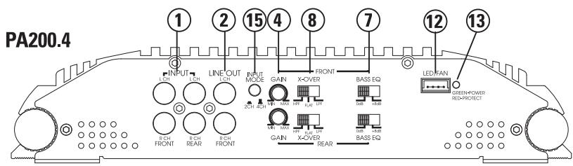
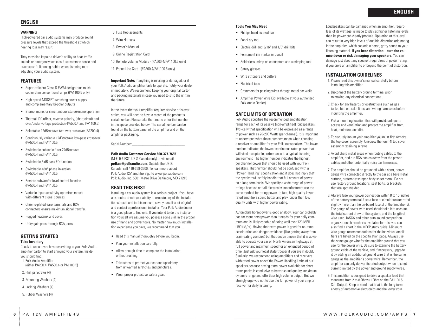
FIGURE 1—AMPLIFIER CONNECTIONS/CONTROLS—FRONT (PA200.4)
FRONT PANEL CONNECTIONS/CONTROLS
- RCA Input Jacks—Accepts line level outputs from head units or signal processors at voltages between 250mV and 7.5 volts. (The PA500.4 and PA1100.5 also have a Rear Input.)
- RCA Line Output Jacks—These pass-through RCA jacks can be used to send the input signal to a second amplifier.
- Line Out Switch (PA1100.5)—three positions: sum L/R—left front and rear and right front and rear channels are summed.
sub L+R—set the switch to this position when using an additional PA600.1 amplifier connected in Parallel mode.
sub 180—set the switch to this position when using an additional PA600.1 amplifier connected in External Bridge mode.
- Gain Control—Controls the amplifier's sensitivity and is used to match the input level of the amplifier to the output level of the signal source (front and rear on PA500.4 and PA1100.5).
- Subsonic Switch—The OFF position takes the filter out of the system, the IN position places the filter into the system (PA1100.5).
- Sub Gain—Subwoofer channel gain adjustment.
-
Bass EQ Switch—Adds 8db additional bass boost (PA200.4 and PA500.4). Allows 8db additional bass boost on the sub channel (PA1100.5).
-
X-Over Selection Switch (HPF, Flat, LPF) The HPF attenuates low frequencies and is used with mid-range speakers and tweeters. Flat does not attenuate any frequencies and is for full range speaker systems. LPF attenuates high frequencies and is used for subwoofer.
- X-Over Frequency—adjusts the crossover point (50-500Hz) for the on-board active crossover (PA500.4 and PA1100.5).
- Remote—Optional accessory which allows the level to be adjusted remotely (usually located for control by the vehicle's driver). (PA500.4 and PA1100.5)
- LPF Control(PA1100.5)—Sets high frequency limit of subwoofer channel.
- LED/FAN—Allows connection of an optional LED light bar or optional cooling fan for the amplifier.
- Status LED—Will illuminate GREEN to indicate the amplifier is on and operating normally, and will be illuminated RED if the amplifier shuts down due to short circuit, DC offset, or overheating detected by onboard protection circuitry.
- Sub Input/Line Out—selects RCA jacks (4) (Sub/ Line Out) as either Subwoofer Input or Line Output (PA1100.5).
- Input Mode Switch—Selects 2 or 4 channel operation (PA200.4 and PA500.4).

FIGURE 1a—AMPLIFIER CONNECTIONS/CONTROLS—FRONT (PA500.4/PA1100.5)

FIGURE 1b- REMOTE (PA500.4/PA1100.5)
Remote—Controls the subwoofer amplifier gain, from a remote location for ease of adjustment during listening.

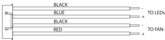
FIGURE 2—LED/FAN HARNESS
REAR PANEL CONNECTIONS
- Fuses—These fuses protect the amplifier against internal electrical damage and are meant to protect the amplifier only. All other power connections should be fused at the source. The PA200.4 uses 1-30A fuse, the PA500.4 uses 2-40A fuses and the PA100.5 uses 3-40A fuses.
- (+) 12 Volt Power—Connect this terminal through a FUSE or CIRCUIT BREAKER to the positive terminal of the vehicle battery or the positive terminal of an isolated audio system battery.
WARNING: Always protect this power wire by installing a fuse or circuit breaker of the appropriate size within 12 inches of the battery terminal connection.
- Remote Turn On—This terminal turns on the amplifier when (+) 12 volt is applied to it. Connect it to the remote turn on lead of the head unit or signal source.
- Ground—Connect this terminal directly to the sheet metal chassis of the vehicle, using the shortest wire necessary to make this connection. Always use wire of the same gauge or larger than the (+) 12 volt power wire. The chassis connection point should be scraped free of paint and dirt. Use only quality crimped and/or soldered connectors at both ends of this wire. DO NOT connect this terminal directly to the vehicle battery ground terminal or any other factory ground points.
- Speaker Terminals—Connect subwoofoers to these terminals. (Refer to the Speaker Wiring Diagrams section of this guide.)

FIGURE 3—AMPLIFIER CONNECTIONS—REAR (PA200.4/PA500.4/PA1100.5)

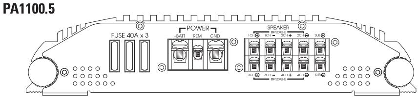
FIGURE 4—SPEAKER WIRING DIAGRAMS (PA200.4)
Stereo Operation—2 Channel (top view)
Stereo Operation-4 Channel (top view)
Passive Tri-Mode (top view)
NOTE: Consult your loudspeaker manufacturer for recommended inductor and capacitor values.
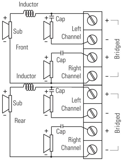
2 Channel Stereo with Mono Sub
(top view) with active crossovers
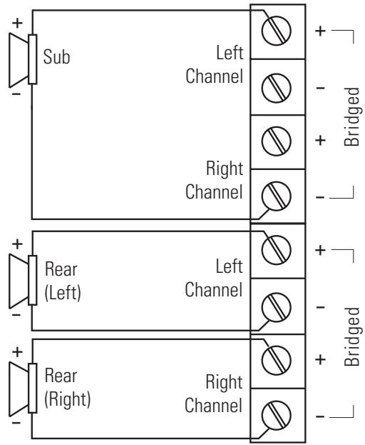
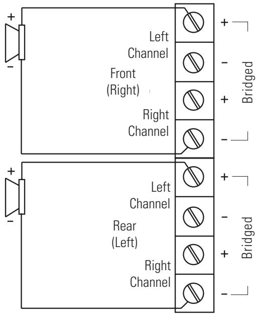
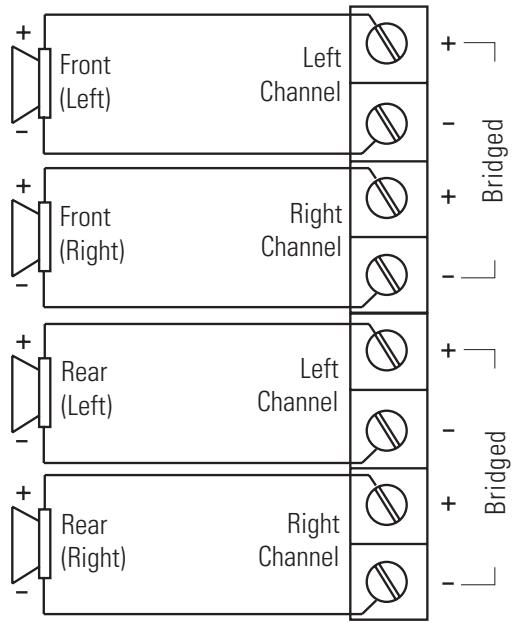
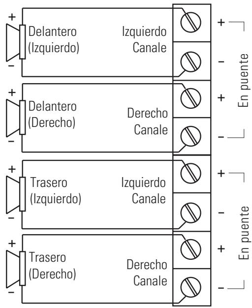
FIGURE 4—SPEAKER WIRING DIAGRAMS (PA500.4)
Stereo Operation (top view)

Bridged Operation (top view)

NOTE: The PA500.4 amplifier connections are the same as shown above, except that there are outputs for Front and Rear Speakers.
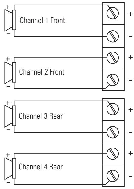
FIGURE 4—SPEAKER WIRING DIAGRAMS (PA1100.5)
Front/Rear Operation (top view)

Front/Rear Bridged Operation (top view)

FIGURE 4—SPEAKER WIRING DIAGRAMS (PA1100.5)
CROSSOVER SETTINGS AND GAIN ADJUSTMENT
Your Polk Audio power amplifier needs to be adjusted carefully to achieve maximum performance. These are some guidelines to follow when fine-tuning the amplifier.
- For full-range and simultaneous stereo/mono bass applications, the crossover selection switch should be set to FULL. If the amplifier is driving your subwoofoers, set the switch to LOW, and for mid-bass/ midrange output, set to HIGH.
-
The crossover frequency control needs to be adjusted to suit your particular system. For subwoofer applications, try and keep the setting low enough to prevent image smearing (you should not be able to hear male voices from the subwoofer) but not so low as to create a gap between the subwoofer and the mid-bass/midrange speakers. For mid-bass/midrange settings, try to keep the setting low enough to keep your sound stage in front of you, without overdriving the speaker. It will be to your advantage to spend some extra time with this adjustment, listening to familiar music or system set-up discs to achieve the kind of musical reproduction that you prefer.
-
The gain adjustment allows you to set proper signal match for clean, quiet amplifier operation. For full-range and simultaneous stereo/mono bass applications, start by playing some music you are familiar with. With the gain adjustment on the amplifier in the middle of its rotation, bring up the volume on your head unit to the 3/4 volume setting or until you start to hear distortion or clipping. If you hear distortion before you reach the 3/4 volume setting of your head unit, reduce the gain setting on the amplifier and start to raise the head unit volume again. When you can listen to the music at or slightly above 3/4 on your head unit without audible distortion, slowly raise the gain of the amplifier until distortion is heard, then back off the gain until the distortion is not audible. This setting will allow you to reach full output with all but the quietest of source material, while avoiding excessive noise in the system.
NOTE: Polk amplifiers use a digital gain control with a finite number of adjustment steps. A very small adjustment may not cause any audible change in level.
LED TUBE INSTALLATION (OPTIONAL)
These Polk Audio amplifiers have been designed with a custom heat sink that can accommodate two (optional—not supplied) VARAD LED tubes.
- Before installing the LED tubes, remove and discard the mounting feet from the VARAD LED tubes.
- Slide each LED tube assembly into your Polk Audio amplifier heat sink. Ensure that the LEDs are facing out for optimal visibility. The wires from the LED tube assembly should be on the signal input end of the amplifier. The Black wire from the LED tube is ground and the Black/White wire from the LED tube is power.
- Run the two wires from the tube assembly and connect them to the 4-pin LED/FAN input connector. Refer to the LED/FAN harness diagram given earlier in this manual.
NOTE: If the optional fan IS NOT being used, we recommend that the second LED tube be wired to this circuit. If the optional fan is being used, we recommend that the second LED tube be wired in parallel with the first LED tube.
SUBSONIC FILTER ADJUSTMENT (PA1100.5 only)
This amplifier uses a subsonic filter to maximize the performance of a subwoofer. The subsonic filter is a high-pass filter that removes unwanted bass output at very low frequencies form the woofer. This increases the output of a subwoofer by as much as 3 dB by increasing the mechanical power handling of the subwoofer. Depending on the type of enclosure the subsonic filter can increase the useable low frequency output by an additional 10dB!
Acceptable boost levels are determined by the type of enclosure used, wattage of the amplifier, and the subwoofer's excursion capability.
The following guidelines should be used for proper set up of the subsonic filter to provide optimum performance and reliability from your system.
CEA SPECIFICATIONS

PA200.4
Power Output: 45 Watts RMS x 4 channels at 4 Ohms and ≤ 1% THD+N
Signal to Noise Ratio: -80 dBA (reference 1 Watt into 4 Ohms)
Additional Power: 50 Watts RMS x 4 channels at 2 Ohms and ≤ 1% THD+N

PA500.4
Power Output: 90 Watts RMS x 4 channels at 4 Ohms and ≤ 1% THD+N
Signal to Noise Ratio: -81 dBA (reference 1 Watt into 4 Ohms)
Additional Power: 125 Watts RMS x 4 channels at 2 Ohms and ≤ 1% THD+N

PA1100.5
Power Output: 80 Watts RMS x 4 channels at 4 Ohms and ≤ 1% THD+N
280 Watts RMS X 1 channel at 4 ohms ≤ 1% THD+N
Signal to Noise Ratio: -80 dBA (reference 1 Watt into 4 Ohms)
Additional Power: 125 Watts RMS x 4 channels at 2 Ohms ≤ 1% THD+N
Additional Power Subchannel: 600Watts RMS x 1 channel at 1 Ohm ≤ 1% THD+N
| SPECIFICATIONS | PA200.4 | PA500.4 | PA1100.5 |
| Dynamic Power Rating | 80W x 4@ 2 Ohms | 200W x 4@ 2 Ohms | 200W x 4 @ 2 Ohms1200W x 1 @ 1 Ohm |
| RMS Continuous PowerBridged @ 4 Ohms | 100W x 2 | 250W x 2 | 250W x 2600W x 1 @ 1 Ohm |
| RMS Continuous Power@ 2 Ohms² | 50W x 4 | 125W x 4 | 125W x 4600W x 1 @ 1 Ohm |
| RMS Continuous Power@ 4 Ohms¹ | 35W x 4 | 90W x 4 | 80W x 4280W x 1 |
| Conversion Efficiency | >66% @ 4 ohms | >66% @ 4 ohms | |
| Frequency Response | 20Hz-20kHz | 20Hz-20kHz | 20Hz-20kHz |
| Signal to Noise Ratio | >90dBA | >98dBA | >98dBA |
| Separation | 65db @ 1kHz | 65db @ 1kHz | 65db @ 1kHz |
| Damping Factor | >100 | >150 | >150(>50 sub channel) |
| Crossover Type/Range | Switchablehigh or low pass | 2-way Butterworth50 to 500Hz | 2-way Butterworth50 to 500Hz |
| Crossover Slope | 12dB/octave | 12dB/octave | 12dB/octave |
| Bass Equalization | +8dB, centered@ 40Hz | 0 to +8dB | 0 to +8dB |
| Subsonic Filter | Variable | ||
| RCA Input/Output Jacks | 2-channel in/2-channelparalleled full range out | ||
| Input Impedance | 20K ohms | 20K ohms | 20K ohms |
| Input Sensitivity | Variable from250mV to 7.5V | Variable from250mV to 8V | Variable from250mV to 8V |
| Supply Voltage | 10-16VDC | 10-16VDC | 10-16VDC |
| Fusing/Type | 1 x 30A | 2 x 40A | 3 x 40A |
| Minimum Cable Required | #10 | #8 | #8 |
| Port Output (Optional Fan)LED(Optiona) | 12V @ <200mA | 12V @ <200mA | 12V @ <200mA |
^1 RMS continuous power driven into 4 Ohms from 20 to 20,000 Hz@14.4VDC with less than 0.08% THD+N.
^2 RMS continuous power driven into 2 Ohms from 20 to 20,000 Hz@14.4VDC with less than 0.15% THD + N .
FRANÇAIS
AVERTISSEMENT
"REMOTE" (PA500.4/PA1100.5)

FIGURE 3—CONNEXIONS—PANNEAU ARRIÈRE (PA200.4/PA500.4/PA1100.5)


FIGURE 4-DIAGRAMMES DE CONNEXION DES HAUT-PARLEURS (PA200.4)
Los sistemas de sonido de automóvil de alta potenciaSEOSEOSEOSEOSEOSEOSEOSEOSEOSEOSEOSEOSEOSEOSEOSEOSEOSEOSEOSEOSEOSEOSEOSEOSEOSEOSEOSEOSEOSEOSEOSEOSEOSEOSEOSEOSEOSEOSEOSEOSEOSEOSEOSEOSEOSEOSEOSEOSEOSEOSEOSEOSEOSEOSEOSEOSEOSEOSEOSEOSEOSEOSEOSEOSEOSEOSEOSEOSEOSEOSEOSEOSEOSEOSEOSEOSEOSEOSEOSEOSEOSEOSEOSEOSEOSEOSEOSEOSEOSEOSEOSEOSEOSEOSEOSEOSEOSEOSEOSEO SEOEO SEOEO SEOEO SEOEO SEOEO SEOEO SEOEO SEOEO SEOEO SEOEO SEOEO SEOEO SEOEO SEOEO SEOEO SEOEO SEOEO SEOEO SEOEO SEOEO SEOEO SEOEO SEOEO SEOEO SEOEO SEOEO SEOEO SEOEO SEOEO SEOEO SEOEO SEOEO SEOEO SEOEO SEOEO SEOEO SEOEO SEOEO SEOEO SEOEO SEOEO SEOEO SEOEO SEOEO SEOEO SEOEO SEOEO SEOEO SEOEO SEOEO SEOEQ
Polk Audio, Inc. 5601 Metro Drive Baltimore, MD 21215
LEA ESTO PRIMERO
FIGURA 1b— REMOTO (PA500.4/PA1
FIGURE 4—SPEAKER WIRING DIAGRAMS (PA200.4)

Funcionamente Estereofonico-2 Canales (vista superior)
Funcionamente Estereofonico-4 Canales (vista superior)
Modalidad Triple Pasiva (vista superior)
REMOTE (PA500.4/PA1100.5)
FIGURA 1b—Telecomando (PA500.4/PA1100.5)
REMOTO (PA500.4/PA1100.5)
Polk Audio is an award-winning designer and manufacturer of high performance audio products and the largest audio brand of Directed Electronics, Inc. (NASDAQ, DEIX). Founded in 1972 by three Johns Hopkins University graduates, Polk Audio holds over 50 patents for advances in loudspeaker design and technology. Polk's products include loudspeakers and electronic components for home, auto and marine applications, the first satellite radio home component tuner, the world's first audiophile-grade active IP-addressable loudspeaker, the first THX Ultra2 Certified in-ceiling loudspeaker, and I-Sonic—the first entertainment system to include HD Radio, XM Connect & Play capability and a DVD player. Polk products are available through authorized specialist consumer electronics retailers worldwide.
For more information and the location of a Polk retailer or distributor in your area please visit www.polkaudio.com or call us at 1-800-377-7655 (M-F, 9-6 EST, US & Canada only). Outside of North America call +1 (410) 358-3600.
Polk Audio, Inc.
5601 Metro Drive, Baltimore, MD 21215
www.polkaudio.com
FRANÇAIS
POLK AUDIO
5601 Metro Drive, Baltimore, MD 21215
www.polkaudio.com
ESPANOL
ACERCA DE POLK AUDIO
5601 Metro Drive, Baltimore, MD 21215
www.polkaudio.com
DEUTSCH
ÜBER POLK AUDIO
5601 Metro Drive, Baltimore, MD 21215
www.polkaudio.com
ITALIANO
5601 Metro Drive, Baltimore, MD 21215
www.polkaudio.com
Polk Audio is a Directed Electronics company which trades on NASDAQ under the symbol DEIX. Investor information can be found at http://investor.directed.com.
"Polk Audio" and "I-Sonic" are registered trademarks of Britannia Investment Corporation used under license by Polk Audio, Inc.
5601 Metro Drive, Baltimore, MD 21215
www.polkaudio.com
Polk Audio, Inc., warrants to the original retail purchaser only. This warranty will terminate automatically prior to its stated expiration if the original retail purchaser sells or transfers the Product to any other party.
Polk Audio, Inc., warrants, to the original retail purchaser only, that the LOUDSPEAKER(S), PASSIVE CROSSOVER COMPON-ENT(S) and ENCLOSURE on this Polk Audio Loudspeaker Product will be free from defects in material and workmanship for a period of one (1) year from the date of original retail purchase from a Polk Audio Authorized Dealer, and 2 years if installed by the same dealer.
To allow Polk Audio to offer the best possible warranty service, please register your new product online at: www.polkaudio.com/registration or call Polk customer service 800-377-7655 in the USA and Canada (outside the USA: 410-358-3600) within ten (10) days of the date of original purchase. Be sure to keep your original purchase receipt.
Defective Products must be shipped, together with proof of purchase, prepaid insured to the Polk Audio Authorized Dealer from whom you purchased the Product, or to the Factory at 2550 Britannia Boulevard, Suite A, San Diego, California 92154. Products must be shipped in the original shipping container or its equivalent; in any case the risk of loss or damage in transit is to be borne by you. If upon examination at the Factory or Polk Audio Authorized Dealer it is determined that the unit was defective in materials or workmanship at any time during this Warranty period, Polk Audio or the Polk Audio Authorized Dealer will, at its option, repair or replace this Product at no additional charge, except as set forth below All replaced parts and Products become the property of Polk Audio. Products replaced or repaired under this warranty will be returned to you, within a reasonable time, freight prepaid.
This warranty does not include service or parts to repair damage caused by accident, disaster, misuse, abuse, negligence, inadequate packing or shipping procedures, commercial use, voltage inputs in excess of the rated maximum of the unit, cosmetic appearance of cabinry not directly attributable to defect in materials or workmanship, or service, repair, or modification of the Product which has not been authorized or approved by Polk Audio. This warranty shall terminate if the Serial number on the Product has been removed, tampered with or defaced.
This warranty is in lieu of all other expressed Warranties. If this Product is defective in materials or workmanship as warranted above, your sole remedy shall be repair or replacement as provided above. In no event will Polk Audio, Inc. be liable to you for any incidental or consequential damages arising out of the use or inability to use the Product, even if Polk Audio, Inc. or a Polk Audio Authorized Dealer has been advised of the possibility of such damages, or for any claim by any other party. Some states do not allow the exclusion or limitation of consequential damages, so the above limitation and exclusion may not apply to you.
All implied warranties on this Product are limited to the duration of this expressed Warranty. Some states do not allow limitation on how long an implied Warranty lasts, so the above limitations may not apply to you. This Warranty gives you specific legal rights, and you also may have other rights which vary from state to state.
This Warranty applies only to Products purchased in Canada, the United States of America, its possessions, and U.S. and NATO armed forces exchanges and audio clubs.
The Warranty terms and conditions applicable to Products purchased in other countries are available from the Polk Audio Authorized Distributors in such countries.