
PSM 900 - Wireless monitoring system SHURE - Free user manual and instructions
Find the device manual for free PSM 900 SHURE in PDF.
| Product Type | Wireless Monitoring System |
| Brand | Shure |
| Model | PSM 900 |
| Transmitter dimensions (P9T) | 197 mm × 166 mm × 42 mm |
| Transmitter weight | 850 g |
| Receiver dimensions (P9R) | 83 mm × 65 mm × 22 mm |
| Receiver weight (with batteries) | 200 g |
| Transmitter power supply | 15 V DC, 415 mA (power adapter included) |
| Receiver power supply | 2 AA batteries (alkaline or NiMH) |
| Battery life (receiver) | 5-7 hours continuous |
| Range | 90 m (300 ft) depending on environment |
| Audio frequency response | 35 Hz – 15 kHz |
| Signal-to-noise ratio (A-weighted) | 90 dB (typical) |
| Total harmonic distortion | <0.8% (typical) |
| Key features | CueMode, MixMode, frequency scan, IR sync, precision RF filtering, Audio Reference Companding compressor, Sound Isolating™ SE425 earphones (optional) |
| Maintenance and cleaning | Keep dry, avoid extreme temperatures, do not modify, clean with a dry cloth |
| Safety | Do not open the device, avoid moisture, set volume as low as possible, adhere to sound exposure limits |
| Replacement parts and accessories | Antennas (UA700, UA720, etc.), cables, power supplies, rack mounts, combiners, etc. See full list in the manual |
| Repairability | Shure after-sales service. Do not attempt to repair yourself |
| General information | Frequency bands: 470-952 MHz depending on region; selectable RF power 10/50/100 mW; stereo or MixMode; LCD display |
Frequently Asked Questions - PSM 900 SHURE
User questions about PSM 900 SHURE
0 question about this device. Answer the ones you know or ask your own.
Ask a new question about this device
Download the instructions for your Wireless monitoring system in PDF format for free! Find your manual PSM 900 - SHURE and take your electronic device back in hand. On this page are published all the documents necessary for the use of your device. PSM 900 by SHURE.
USER MANUAL PSM 900 SHURE
Personal Monitor Wireless System
USE AS LOW A VOLUME AS POSSIBLE.
Over exposure to excessive sound levels can damage your ears resulting in permanent noise-induced hearing loss (NIHL). Please use the following guidelines established by the Occupational Safety Health Administration (OSHA) on maximum time exposure to sound pressure levels before hearing damage occurs.
90 dB SPL
at 8 hou
95 dB SPL
at 4 hours
100 dB SPL
at 2 hours
105 dB SPL
at 1 hour
110 dB SPL
at 1 / 2 hour
115 dB SPL
at 15 minutes
120 dB SPL
Avoid or damage may occur
SAFETY PRECAUTIONS
The possible results of incorrect use are marked by one of the two symbols - "WARNING" AND "CAUTION" - depending on the imminence of the danger and the severity of the damage.

WARNING: Ignoring these warnings may cause severe injury or death as a result of incorrect operation.

CAUTION: Ignoring these cautions may cause moderate injury or property damage as a result of incorrect operation.

WARNING
- If water or other foreign objects enter the inside of the device, fire or electric shock may result.
- Do not attempt to modify this product. Doing so could result in personal injury and/or product failure.
WARNING: This product contains a chemical known to the State of California to cause cancer and birth defects or other reproductive harm

CAUTION
- Never disassemble or modify the device, as failures may result.
- Do not subject to extreme force and do not pull on the cable or failures may result.
- Keep the microphone dry and avoid exposure to extreme temperatures and humidity.

DVERTENCIA
EL ESCUCHAR REPRODUCCIONES DE AUDIO A NIVELES EXCESIVOS DE VOLUMEN PUEDE CAUSAR DANOS PERMANENTES AL OIDO. USE EL VOLUMEN MAS BAJO POSIBLE.
YKA3AHM NTO XEHNKE 6E3ONACHOCTH
Bo3MOXHbIe pe3yIbTaI heNpaBnIbHorO hCNoJIb3OBAHnI OTMueHebl ODNHM n3 DByx 3NaKOB - «BHIMAHHE» N «OCTOPOXHO» - B 3aBcImoCTn OT HeN36BeXHocTn OnaChOCTn I cepBe3HocTn IOBpeJdEHH.

BHIMAHHE: INHORIPoBaHHe 3THN pReDynpEJxHn MOKeT pINBeCTn K cepbEsHn TpaBMe Hn CMePTn B pe3yIbTaTe HEnpABlbHOH 3KcNpLyataaun.

OCTOPOXHO: HrhopnpoBaHne 3THx npeDynpEckJeHm MoKet npBecTe K He3NaHTeBHO TpaBMe IINI NOBpeKDeHIO IMUjcctBA B pe3yJIbTaTe PaBInbHO 3KcPJIyatauIN.

BHIMAHNIE
- EcnB UcTpoiCTBO nonaTeT BODa HINn HNble NocToPOHHne npeDMtbl, 3TO MOKeT npInBeCTN K Bo3rOpauHIO INn nopaxHeHIO 3NeKTPnuCeckMn TOkOM.
HeIbTaIteCbMoINHcHIpOBaTb3To H3dJIeNe.3To MoKET npNBecTN K IInuHOI TpaBMe N (nIn) nOLOMKe H3dJIeNIA.

OCTOPOXHO
HnB KOem cnyae He pa3bnpaIte H Me MOINΦuNpUyTe 3TO yCTPOIcTBO, NockoJIky 3TO MoKET npNBecTNI POJOMKe.
- He noDBepratae cnIbHbIM Harpy3KaM I He TAHnte 3a Ka6eJIb - 3TO MOKeT npIBecTI K NOIOMKe.
- Copepknte MmKpofoh cyxHm Hne noDBeprAte ero BO3dEiCTBnO OueHb BbICOKNX HIN HN3KHX TempePty N BlaJHKoCTH.
PSM900
The PSM 900 Wireless Personal Monitor System from Shure offers an unprecedented combination of superb audio quality, robust RF performance, and category-leading setup features for the most demanding professional applications. All new, patent-pending CueMode allows the sound engineer to monitor different stage mixes with the touch of a button. Precision front-end RF filtering significantly reduces dropouts from RF interference, and the enhanced digital stereo encoder provides excellent stereo separation and audio clarity.
Features
Superb audio quality
- Digital stereo encoder provides a wider stereo field with exceptional separation, enhancing audio detail and clarity
- Patented Audio Reference Companding sounds more like wired
- Available with Shure SE425 Sound Isolating™ Earphones featuring dual high-definition MicroDrivers for accurate and balanced audio response
Robust RF Performance
- Precision front-end RF filtering for a cleaner, stronger RF signal and fewer dropouts and audible artifacts.
- Exceptional transmitter linearity vastly reduces frequency intermodulation, allowing more channels per frequency band.
Automatic RF gain control prevents signal distortion due to RF overload.
Advanced Setup and Operation
- Patent-pending CueMode allows monitoring of the stage mixes of up to 20 separate transmitters from one bodypack.
- Front panel RF mute switch for disabling RF transmission during setup
- Scan and Sync setup identifies the best group and channel for your system and assigns it over a wireless IR link
- MixMode® Technology allows the bodypack user to adjust their own onstage monitor mix
High-frequency EQ boost on bodypack
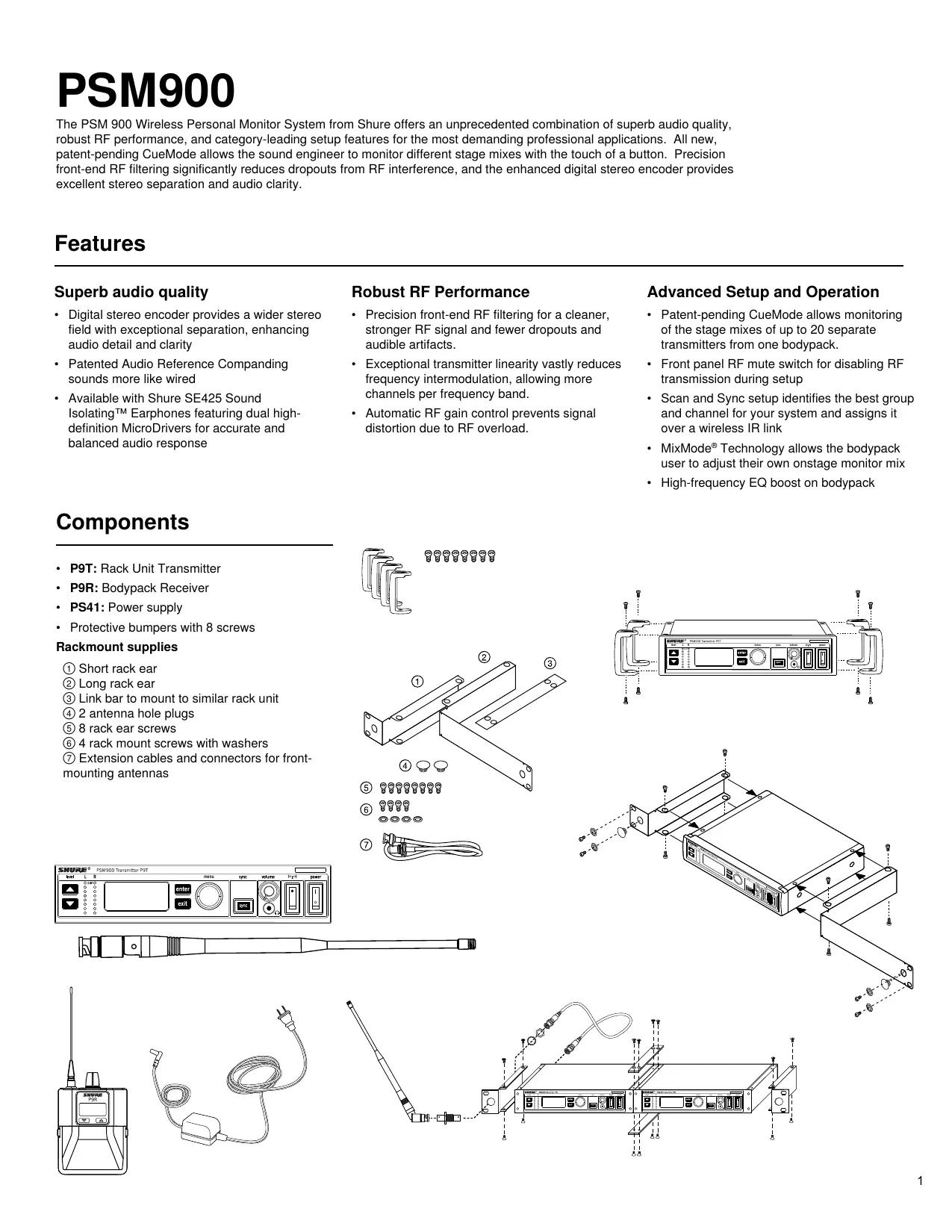
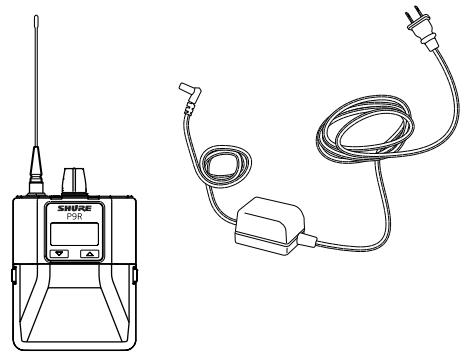
Components
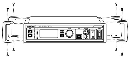
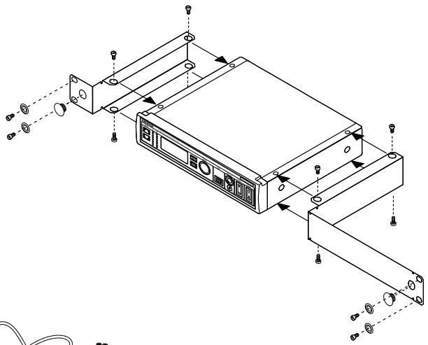
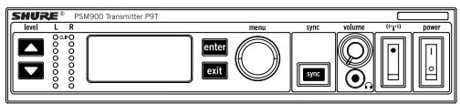
P9T: Rack Unit Transmitter
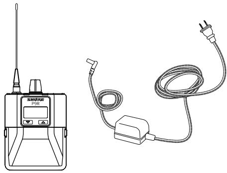
P9R: Bodypack Receiver
PS41: Power supply
- Protective bumpers with 8 screws
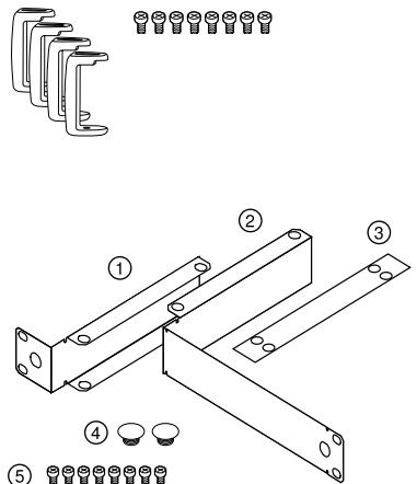
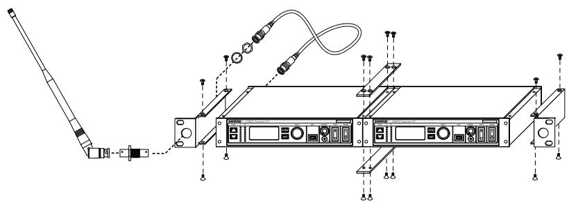
Rackmount supplies
① Short rack ear
② Long rack ear
③ Link bar to mount to similar rack unit
④ 2 antenna hole plugs
⑤ 8 rack ear screws
⑥ 4 rack mount screws with washers
(7) Extension cables and connectors for frontmounting antennas
6
⑦

Rack Unit
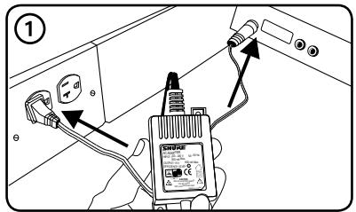
- Connect to a power outlet using the supplied power adapter.
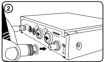
- Attach the supplied antenna to the ANTENNA OUT BNC connector.
-
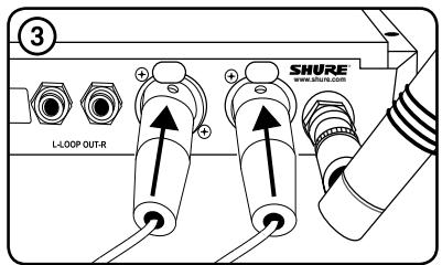
Connect the audio source, such as the output of a mixer, to the audio inputs. You can use both input jacks or choose either one for a mono source.
-
For mono (one input), access the AUDIO menu and select MONO.
-
Set the input sensitivity to match the source by selecting AUDIO>INPUT from the LCD configuration menu: AUX -10dBV or LINE+4dBu.
-
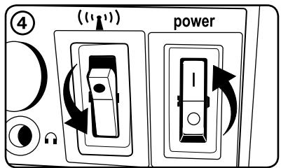
Turn the power ON. Make sure the RF switch is OFF.
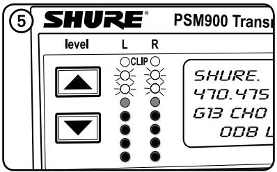
- Adjust the audio source level so that, for the average input signal level, the top two yellow LEDs flicker and the lower LEDs are solid.
- If the red clip LED illuminates, the inputs are overdriven. Decrease the level using the buttons or change the input sensitivity to +4 dBu.
- If the signal level is too low, change the input sensitivity to -10dBV .
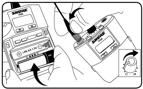
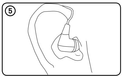
Bodypack
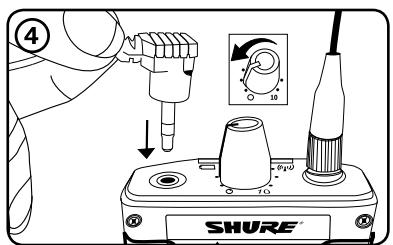
Insert batteries and attach antenna. Turn on using the volume knob. The battery light illuminates.
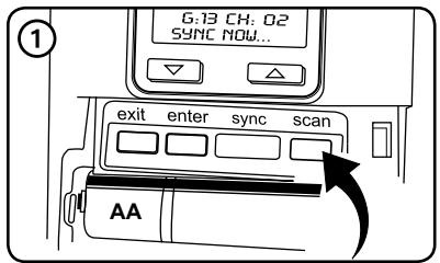
Scan and Sync
- Press the scan button. The display flashes SYNC NOW . . .
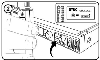
- Align the IR windows on the bodypack and rack unit and press the sync button. The rack unit level LEDs flash, and it displays SYNC SUCCESS.
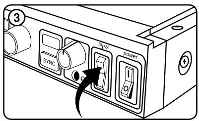
- Turn the RF switch on. The blue RF LED illuminates on the bodypack to indicate that it is detecting the transmitter. The bodypack also displays the RF signal strength (RF).
- IMPORTANT: Turn bodypack volume down before plugging in earphones.
- Insert the earphones and slowly turn up the volume.
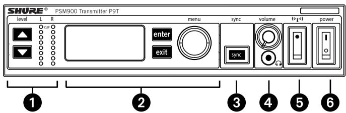
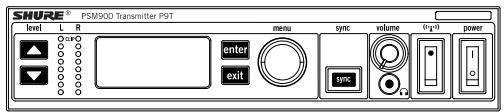
Front Panel Controls
① Input Level Control and Display Use the buttons to adjust the audio so that, for the average input signal level, the top two yellow LEDs flicker and the lower LEDs are solid. The red clip LED indicates the inputs are overdriven. Reduce the level at the audio source or change the input sensitivity of the rack unit from the AUDIO>INPUT menu.
(2) Status Display and Menu Controls Use the enter and exit buttons and the menu wheel to access the configuration menu. Push the menu wheel to move the cursor to the next item. Turn the menu wheel to change a parameter—the enter button flashes. Press it to save the value. Press the exit button to cancel changes and return to the previous menu.
③ Synchronization Button Press the sync button while rack unit and bodypack IR windows are aligned to transfer settings.
④ Headphone Monitoring The volume control adjusts signal output to the 3.5mm headphone jack. NOTE: it does not affect rear panel outputs.
⑤ RF switch mutes RF output. For setting up multiple systems or adjusting settings without transmitting unwanted RF or audio signals.
⑥ Power Button Turns the unit on and off.
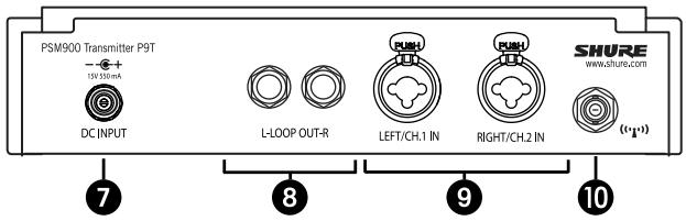
Rear Panel Connectors
⑦ Power Connect the transmitter to a power outlet using the supplied power adapter.
⑧ LOOP OUT Sends a copy of the audio signal going into the transmitter to another device. See LOOP Applications.
⑨ Audio Inputs Connect to balanced or unbalanced outputs. Use either connector for mono input. Accepts both 1/4-inch or male XLR connectors.
Antenna (BNC) Attach supplied antenna. If you are rack mounting, use a front panel or remote mounting kit from Shure.
RF Settings
| RADIO | |
| G | Sets the group number |
| CH | Sets the channel number |
| 888.888MHz | Manual frequency selection |
| RF POWER | Select from 10, 50, or 100 mW (varies by region) |
Audio Settings
| AUDIO | ||
| MODE | Selects monitor mode | |
| STEREO/MX | Transmits both channels | |
| MONO | Transmits a mono signal to bodypack | |
| INPUT | Sets nominal input level | |
| LINE +4 dBu | line level | |
| AUX -10dBV | aux level | |
Utilities and Display Settings
| UTILITIES | ||
| EDIT NAME | Changes the name on the LCD display (this name is uploaded to the bodypack with sync) | |
| DISPLAY | Changes the display format | |
| CONTRAST | Changes the display contrast | |
| LOCK PANEL | Locks front panel controls. To unlock, press exit, select OFF, and press enter. | |
| MENU+LEVEL | Locks menu and level controls. | |
| MENU ONLY | Locks only the configuration menu (menu controls). | |
| MENU+SWITCH | Locks all controls except for the level buttons (including the RF and power switches).* | |
| ALL | Locks all controls (including the RF and power switches).* | |
| *RF is automatically activated when locked. When you unlock the unit, RF and power turns off if the switches are off. | ||
| RX SETUP | These settings are sent to theBODYPACK during a sync (when the sync direction is from the transmitter). The default KEEP parameter will not change theBODYPACK settings. | |
| LOCK | LockBODYPACK | |
| V LIMIT | Volume limiter | |
| LIM VAL | Volume limiter value | |
| MODE | Stereo (ST) or MixMode (MX) | |
| BAL MX | CH.1 (L) and CH.2 (R) mix for MixMode | |
| BAL ST | Left (L) and right (R) balance for stereo mode | |
| HIBOOST | high frequency boost | |
| CUSTOM GROUP | For creating custom frequency groups | |
| RESET SYSTEM | Returns all settings to the factory defaults. | |
| NO | Exit and do not reset system. | |
| YES | Reset system settings. | |
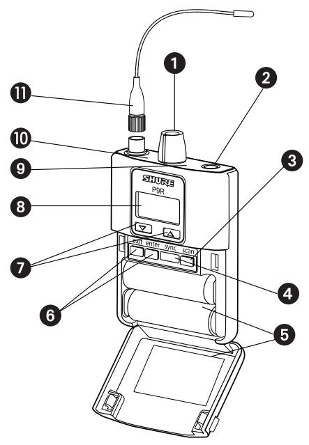
Bodypack Receiver
① Power Switch and Volume Control Turns the bodypack on and off and adjusts earphone volume.
② 3.5 mm Earphone Jack Insert earphones here.
③ Scan Button Press the scan button to find an available frequency. Press and hold for two seconds to find the group with the most available channels.
④ IR Window For transmitting settings between bodypack and rack unit.
⑤ Battery Compartment Requires 2 AA batteries. Open by pressing the latches on both sides and pulling.
⑥ Menu buttons Use in conjunction with the buttons to access the configuration menus.
(7) Buttons Use to adjust the audio mix (in MixMode only), or in conjunction with the menu buttons to change settings.
⑧ LCD Screen Displays current settings and menus.
⑨ Tri-Color Battery LED illuminates green, orange, red, or flashing red, to indicate battery power. When flashing red, change batteries immediately.
Blue RF LED Indicates the bodypack is receiving a signal from the transmitter.
① Detachable Antenna SMA Connector
| Battery Indicator | Tri-Color Battery LED | Approximate Hours Remaining | |
| Alkaline | NiMH (2450 mAh) | ||
| Green | 5–7 | 4 | |
| Green | 3½–4 | 3–3½ | |
| Green | 3–3½ | 1½–2 | |
| Green | 2–2½ | ½ | |
| Orange | ½–1 | 0 | |
| Red | ½–½ | 0 | |
RF Settings
| RADIO | |
| G | Sets the group number |
| CH | Sets the channel number |
| 888.888MHz | Manual frequency selection |
Audio Settings
| AUDIO | ||
| MODE | Selects monitor mode | |
| STEREO | Stereo | |
| MIXMODE | MixMode | |
| HIBOOST | High-frequency EQ boost | |
| OFF | flat | |
| 4 dB | +4 dB @ 10 kHz | |
| 2 dB | +2 dB @ 10 kHz | |
| V LIMIT | ||
| ON | Limits volume level | |
| VALUE | 3-9: analogous to volume knob position (for example, 5 is equal to the 5th dot on the volume knob) | |
| BAL ST / BAL MX | Left and right balance for earphones when in stereo mode, or mix of left and right channel for MixMode | |
Utilities and Display Settings
| UTILITIES | |
| CUEMODE | Enters CueMode (to exit, press enter and select EXIT CUEMODE) |
| DISPLAY | Changes the display format |
| CONTRAST | Changes the display contrast |
| LOCK PANEL | Locks all controls except power and volume. To unlock, press exit, select OFF, and press enter. |
When setting up multiple systems, designate a single bodypack to scan for available frequencies and download them to all the rack units.
The bodypack must be from the same frequency band as all the transmitters.
- Power on all the rack units. Turn off the RF. (This prevents them from interfering with the frequency scan.)
Note: Turn on all other wireless or digital devices as they would be during the performance or presentation (so the scan will detect and avoid any interference they generate). - Use theBODYPACK to scan for a group by pressing and holding the scan button for two seconds. TheBODYPACK displays the group and the number of available channels, and flashes SYNC NOW...
Important: Note the number of available channels. If you have more rack units than available channels, eliminate potential sources of interference and try again, or call Shure Applications for assistance. - Sync the bodypack with the first rack unit by aligning the IR windows and pressing sync.
- Press scan again on the bodypack to find the next available frequency.
- Sync the bodypack with the next rack unit.
- Repeat with all the rack units.
- Sync each performer's bodypack to its respective rack unit by aligning the IR windows and pressing smyc. DO NOT press scan on the bodypacks.
- Turn on the RF on all rack units. The systems are ready to use.
MixMode for Multiple Systems
Configure each system for MixMode. From the mixing console, send a mix of the whole band to input 2 of the first transmitter. Connect the LOOP OUT R output to the CH. 2 IN input of the next transmitter. Continue the chain with all the transmitters.
Next, create solo mixes for each performer. Send each mix to input 1 of the transmitter for that performer.
CueMode
CueMode allows you to upload the name and frequency settings from multiple rack units and store them as a list on a single bodypack. You can then, at any time, scroll through that list to hear the audio mix from each transmitter, just as each performer does during a show.
CueMode lists are retained even if CueMode is exited, the bodypack is turned off, or batteries are removed.
Note: Set the channel frequency and assign display names for each transmitter before creating your CueMode list.
Adding Transmitters to the CueMode List
Note: The transmitter must be from the same frequency band as the bodypack.
- Open the battery door and press the enter button.
- From the main menu, scroll to UTILITIES and press enter. Select CueMode and press enter again.
- Align IR windows and press sync on the rack unit.
The LCD displays SYNC SUCCESS after frequency and name data are uploaded to the CueMode list. It also displays the CueMode number for that transmitter and the total number of transmitters.
- Repeat the above step for each transmitter.
Note: Syncing while in CueMode does not change any of the settings on the bodypack.
Auditioning Mixes
- Enter CueMode from the UTILITIES menu.
- Use the buttons to scroll through your CueMode list to hear the mixes.
Exiting CueMode
Exit CueMode by pressing enter and selecting EXIT CUEMODE.
Managing CueMode Mixes
While in Cue Mode, you can access the following menu by pressing enter:
REPLACE MIX Select and press sync on a rack unit to upload new data for the current mix (for example, if you have changed the transmitter frequency).
DELETE MIX Removes the selected mix.
DELETE ALL Removes all mixes.
EXIT CUEMODE Exits CueMode and returns theBODYPACK to the previous frequency setting.
The scan feature analyzes the RF environment for interference to identify available frequencies. The PSM900 has two frequency scan modes:
- Channel Scan Press the scan button on the bodypack. Finds the first available channel.
- Group Scan Press and hold the scan button for two seconds. Finds the group with the greatest number of available channels. (Each group contains a set of frequencies that are compatible when operating multiple systems in the same environment.)
Sync
The PSM900 transfers settings in either direction: from the bodypack to the rack unit, or from the rack unit to the bodypack.
- Sending settings to theBODYPACK: Align the IR windows and press the sync button on the rack unit. The blue LED on theBODYPACK flashes.
- Downloading settings from theBODYPACK: First press the scan button on theBODYPACK. Then align the IR windows and press the sync button on the rack unit while theBODYPACK display is flashing "SYNC NOW...". The level LEDs flash on the rack unit.
MixMode
Some performers need to hear more of their own voice or instrument, while others want to hear more of the band. With MixMode, the performer creates their own mix using the balance control (▼▲ buttons) on the bodypack.
To use MixMode, send a solo mix of the performer to the CH. 1 IN input on the transmitter, and send a band mix to the CH. 2 IN input.
Set the performer's bodypack for MixMode. The bodypack combines the two signals and sends them to both earphones, while the balance control on the bodypack adjusts the relative levels for each.
LOOP Applications
Use LOOP OUT L (left) and R (right) outputs to send a copy of the audio signal going into the transmitter to other devices. Following are a few of the many applications for these outputs.
Note: The input level control and the input pad do not affect the LOOP OUT signals.
Stereo for Multiple Systems
Send one stereo signal from the mixing console to the inputs on the first transmitter, then connect the LOOP outputs to the inputs on the next transmitter. Repeat for all transmitters to form a chain.
Floor Monitors
Send the audio from the LOOP outputs to onstage loudspeakers. The bodypack and the onstage monitors receive the same audio signals.
Recording Devices
To record a performance, connect the LOOP outputs to the inputs of a recording device.
Squelch
Squelch mutes audio output from the bodypack when the RF signal becomes noisy. While squelch is activated, the blue LED on the bodypack turns off.
For most installations, squelch does not need adjustment, and it keeps the performer from hearing hiss or noise bursts if the RF signal becomes compromised. However, in congested RF environments or in close proximity to sources of RF interference (such as large LED video panels), the squelch may need to be lowered to prevent excessive audio dropouts. With lower squelch settings, the performer may hear more noise or hiss, but will experience fewer audio dropouts.
Note: Before lowering squelch, first try to eliminate the problem by finding the best set of frequencies for your installation and removing potential sources of interference.
Caution: Turning off or lowering the squelch setting can increase the noise level and cause discomfort to the performer:
- Do not lower the squelch setting unless absolutely necessary.
- Turnearphone volume to the lowest setting before adjusting squelch.
- Do not change the squelch setting during a performance.
- Turn up the transmitter setting to make noise or hiss less noticeable.
Squelch Settings
| HIGH (NORMAL) | Default factory setting. |
| MID | Moderately decreases the signal-to-noise ratio required to squelch the receiver. |
| LOW | Greatly decreases the noise squelch threshold. |
| PILOT ONLY | Turns off noise squelch leaving only pilot squelch on. |
| Symbol appears in display window | |
| NO SQUEELCH | Turns off noise and pilot tone squelch. (Sometimes used as a debugging tool by monitor engineers or RF coordinators to “listen” to the RF environment.) |
| Symbol appears in display window |
Point-to-Point Wireless Audio
When a cable cannot be used, a UR4 receiver and a P9T transmitter can be used for point-to-point (PTP) wireless audio.
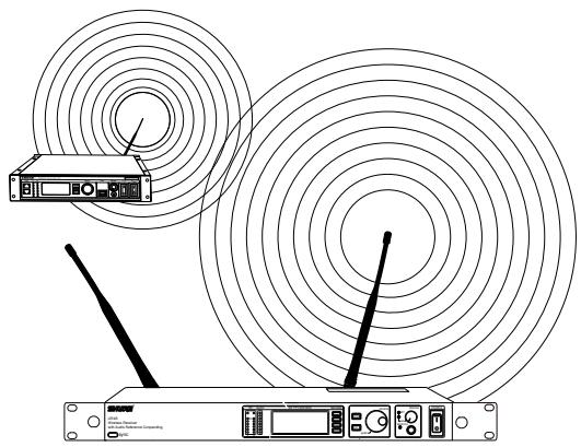
For more information on PTP, please visit:
www.shure.com/américas/products/personal-monitor-systems/psm900
PSM900
RF Carrier Range
470-952MHz
Note: varies by region
Compatible Frequencies
Per band: 20
Tuning Bandwidth
US:36-40MHz
varies by region
Operating Range (environment dependent)
90 m (300 ft)
Audio Frequency Response
35 Hz-15 kHz
Stereo Separation
60 dB
Signal-To-Noise Ratio (A-Weighted)
90 dB (typical)
Total Harmonic Distortion (ref. ± 34kHz deviation
@1 kHz)
<0.8% (typical)
Companding
Patented Shure Audio Reference Companding
Spurious Rejection (ref. 12dB SINAD)
80 dB (typical)
Frequency Stability
±2.5 ppm
MPX Pilot Tone
19 kHz (±0.3 kHz)
Modulation
FM*, MPX Stereo
- ±34 kHz deviation (nominal)
Operating Temperature
-18°C-+57°C
P9R
Front-End RF Filtering
-3 dB at 30.5 MHz from center frequency
Active RF Gain Control
31 dB
Adjusts RF sensitivity to provide more RF dynamic range
RF Sensitivity (at 20 dB SINAD)
2.2 V
Image Rejection
100 dB
Adjacent Channel Rejection
70 dB
Squelch Threshold
22 dB SINAD (± 3dB)
Intermodulation Attenuation
70 dB
Blocking
80 dB
Audio Output Power (1kHz @ <1% distortion, peak
power, @32Ω)
100 mW per output
Minimum Load Impedance
9.5Ω
High Boost
selectable selectable: +2 dB , +4 dB @ 10 kHz
Volume Limiter
selectable selectable: 3-9
Reduces maxium output level. Selected value analogous to vol
ume knob increment.
Net Weight
200 g (with batteries)
Dimensions
83 mm X 65 mm X 22 mm
Battery Life
5-7 hours (continuous use)
P9T
RF Output Power
selectable selectable: 10, 50, 100 mW (+20 dBm)
varies by region
RF Output Impedance
50Ω (typical)
Net Weight
850g
Dimensions
197 mm X 166 mm X 42 mm
Power Requirement
15 Vdc: 415 mA, typical
Audio Input
Connector Type
Combination XLR and 6.35mm (1 / 4^ ) TRS
Polarity
XLR: Non-inverting (pin 2 positive with respect to pin 3)
6.35 mm (1/4") TRS: Tip positive with respect to ring
Configuration
Electronically balanced
Impedance
70.2 kΩ (actual)
Nominal Input Level
switchable switchable: +4 dBu, -10 dBV
Maximum Input Level
+4 dBu: +29.2 dBu
-10 dBV: +12.2 dBu
Pin Assignments
XLR: 1=ground, 2=hot, 3=cold
6.35 mm (1/4") TRS: Tip=hot, Ring=cold,
Sleeve=ground
Phantom Power Protection
up to 60 V DC
Audio Output
Connector Type
6.35 mm (1/4") TRS
Configuration
Electronically balanced
Impedance
Connected directly to inputs
| Band | Range (MHz) | Output Power (mW) |
| G6 | 470-506 | 10 / 50 / 100 |
| G6E | 470-506 | 10 / 50 |
| G7 | 506-542 | 10 / 50 / 100 |
| G7E | 506-542 | 10 / 50 |
| K1 | 596-632 | 10 / 50 / 100 |
| K1E | 596-632 | 10 / 50 |
| L6 | 656-692 | 10 / 50 / 100 |
| L6E | 656-692 | 10 / 50 |
| P7 | 702-742 | 10 / 50 |
| Q15 | 750-790 | 10 / 50 |
| Q20 | 750-787 | 10 / 50 |
| R20 | 794-806 | 10 |
| R21 | 794-806 | 10 / 50 |
| R22 | 790-830 | 10 / 50 |
| A24 | 779-806 | 10 |
| X2 | 925-932 | 10 |
| X1 | 944-952 | 10 / 50 / 100 |
NOTE:
This Radio equipment is intended for use in musical professional entertainment and similar applications.
This Radio apparatus may be capable of operating on some frequencies not authorized in your region. Please contact your national authority to obtain information on authorized frequencies and RF power levels for wireless microphone products.
Furnished Accessories
| P9R Antenna | |
| 470-542 MHz | UA700 |
| 596-692 MHz | UA720 |
| 692-830 MHz | UA730 |
| 830-952 MHz | UA740 |
| P9T Antenna | |
| 470-530 MHz | UA820G |
| 500-560 MHz | UA820G7 |
| 518-578 MHz | UA820H4 |
| 578-638 MHz | UA820J |
| 638-698 MHz | UA820L3 |
| 690-746MHz | UA820B |
| 740-814 MHz | UA820Q |
| 774-865 MHz | UA820A |
| 900-1000 MHz | UA820X |
| Front Mount Antenna Cable | 95A9023 |
| Zipper Bag | 95A2313 |
| Rackmount Bracket, Long | 53A8612 |
| Rackmount Bracket, Short | 53A8611 |
| Link Bar | 53B8443 |
| Hardware Kit (Rackmounting Screws) | 90AR8100 |
| Bumper Kit | 90B8977 |
| Energy Efficient Switching Power Supply | |
| USA | PS41US |
| Brazil | PS41BR |
| Argentina | PS41AR |
| Europe | PS41E |
| United Kingdom | PS41UK |
| Austrailia/New Zealand | PS41AZ |
| China | PS41CHN |
| Taiwan | PS41TW |
| Japan | PS41J |
Optional Accessories
| 8-to-1 antenna combiner for better RF performance | PA821SWB |
| 4-to-1 antenna combiner with power dis-ribution to 4 transmitters (better RF performance and eliminates need for external power supply) | PA421SWB |
| Passive Directional Antenna | PA805SWB |
| Helical Antenna | HA-8089 |
| Passive Omnidirectional Antenna | UA860SWB |
| 4-Channel Personal Monitor Mixer | P4M |
| Coaxial Cable, BNC-BNC, RG58C/U type, 50 Ohm, 2 ft length (0.6 m) | UA802 |
| Coaxial Cable, BNC-BNC, RG58C/U type, 50 Ohm, 6 ft length (2 m) | UA806 |
| Coaxial Cable, BNC-BNC, RG8X/U type, 50 Ohm, 25 ft length (7.5 m) | UA825 |
| Coaxial Cable, BNC-BNC, RG8X/U type, 50 Ohm, 50 ft length (15 m) | UA850 |
| Coaxial Cable, BNC-BNC, RG213/U Type, 50 Ohm, 100 ft length (30 m) | UA8100 |
P9T, P9R
This Class B digital apparatus complies with Canadian ICES-003.
Meets requirements of EMC standards EN 300 422 Parts 1 and 2 and EN 301 489 Parts 1 and 9.
P9T
Certified under FCC Parts 74. (FCC ID: DD4P9TA, DD4P9TB, DD4P9TC, DD4P9TD, DD4P9TJ). Certified by IC in Canada under RSS-123 and RSS-102. (IC: 616A-P9TA, 616A-P9TB, 616A-P9TC, 616A-P9TD). Meets essential requirements of European R&TTE Directive 99/5/EC, eligible to bear the CE mark.
P9R
Approved under the Declaration of Conformity (DoC) provision of FCC Part 15. Certified in Canada by IC to RSS-123. (IC: 616A-P9RA, 616A-P9RB, 616A-P9RC, 616A-P9RD).
Operation of this device is subject to the following two conditions: (1) this device may not cause interference, and (2) this device must accept any interference, including interference that may cause undesired operation of the device.
The CE Declaration of Conformity can be obtained from Shure Incorporated or any of its European representatives. For contact information please visit www.shure.com The CE Declaration of Conformity can be obtained from:
Authorized European representative:
Shure Europe GmbH
Headquarters Europe, Middle East & Africa
Department: EMEA Approval
Wannenacker Str. 28
D-74078 Heilbronn, Germany
Phone: +49 7131 72 14 0
Fax: +49 7131 72 14 14
Email: EMEAsupport@shure.de
INFORMATION TO USER
This equipment has been tested and found to comply with the limits for a Class B digital device, pursuant to Part 15 of the FCC Rules. These limits are designed to provide reasonable protection against harmful interference in a residential installation. This equipment generates, uses and can radiate radio frequency energy and, if not installed and used in accordance with the instructions, may cause harmful interference to radio communications. However, there is no guarantee that interference will not occur in a particular installation. If this equipment does cause harmful interference to radio or television reception, which can be determined by turning the equipment off and on, the user is encouraged to try to correct the interference by one or more of the following measures:
- Relocate the receiving antenna.
- Increase the separation between the equipment and receiver.
- Connect the equipment into an outlet on a circuit different from that to which the receiver is connected.
- Consult the dealer.
Note: EMC conformance testing is based on the use of supplied and recommended cable types. The use of other cable types may degrade EMC performance.
Changes or modifications not expressly approved by the manufacturer could void the user's authority to operate the equipment.
LICENSE INFORMATION
Licensing: A ministerial license to operate this equipment may be required in certain areas. Consult your national authority for possible requirements. Changes or modifications not expressly approved by Shure Incorporated could void your authority to operate the equipment. Licensing of Shure wireless microphone equipment is the user's responsibility, and licensability depends on the user's classification and application, and on the selected frequency. Shure strongly urges the user to contact the appropriate telecommunications authority concerning proper licensing, and before choosing and ordering frequencies.
PSM900
Solides performances HF
Commande de gain RF active
31 dB
XLR: Non-inverting (pin 2 positive with respect to pin 3)
TRS 6,35 mm (1/4 po): Tip positive with respect to ring
Configuration
Symétrique
Impedance
70.2k (reelle)
XLR: 1=ground, 2=hot, 3=cold
TRS 6,35 mm (1/4 po): Tip=hot, Ring=cold,
Sleeve = ground
Service : Homologation EMA
Wannenacker Str. 28
XLR: Non-inverting (pin 2 positive with respect to pin 3)
6,35 mm TRS: Tip positive with respect to ring
Konfiguration
XLR: 1=ground, 2=hot, 3=cold
6,35 mm TRS: Tip=hot, Ring=cold, Sleeve=ground
selectionable: +2 dB , +4 dB @ 10 kHz
selectionable: 10, 50, 100 mW (+20 dBm)
XLR: Non-inverting (pin 2 positive with respect to pin 3)
TRS de 6,35 mm (1/4 pulp): Tip positive with respect
to ring
Configuración
XLR: 1=ground, 2=hot, 3=cold
TRS de 6,35 mm (1/4 pulp): Tip=hot, Ring=cold,
Sleeve=ground
selectionable: +2 dB, +4 dB @ 10 kHz
selectionable: 10, 50, 100 mW (+20 dBm)
XLR: Non-inverting (pin 2 positive with respect to pin 3)
TRS da 6,35 mm (1/4 di pollice): Tip positive with
respect to ring
Configurazione
Bilancimiento elettronico
Impedenza
70.2 kΩ (effettivo)
Livello d'ingresso nominale
commutabile: +4 dBu, -10 dBV
Livello massimo d'ingresso
+4 dBu: +29.2 dBu
-10 dBV: +12.2 dBu
XLR: 1=ground, 2=hot, 3=cold
TRS da 6,35 mm (1/4 di pollice): Tip=hot, Ring=cold,
Sleeve = ground
Department: EMEA Approval
Wannenacker Str. 28
D-74078 Heilbronn, Germania
Numero Telefonico: +49 7131 72 14 0
Fax: +49 7131 72 14 14
E-mail: EMEAsupport@shure.de
INFORMAZIONI PER L'UTILIZZATORE
XLR: Non-inverting (pin 2 positive with respect to pin 3)
6,35 mm (1/4") TRS: Tip positive with respect to ring
Configuração
XLR: 1=ground, 2=hot, 3=cold
6,35 mm (1/4") TRS: Tip=hot, Ring=cold,
Sleeve=ground
Headquarters Europe, Middle East & Africa
Department: EMEA Approval
Wannenacker Str. 28
PpHaJNeXHOCTHIyCTaHOBKn B CToiKe
① KoporTkni KpoHHTeIN CToiKn
②ДлHHbI KPOHHTeH CTOIKN
③ CoeHHnHTeHoe 3BeHO nla yCTaHOBKn Ha aHaNoTnHOM npHeMHnKe
④ 23aŋyuδn OTBεpCTnДЯ aHTeHH
⑤ 8 BnHTOBДЛЯ KPOHUsTeHOB CToIKN
⑥ 4 BnHTa C ShaH6amn Dlny yCTaHOBKn B CTOnKe
⑦ Ka6eHn-ynHnHTeHn pa3bEmbl dIa aHTeHH npeedHe yCTaHOBKn

BcnoMoraTeIbHbIe HacTpoIKN I npaMeTpbl IncIpeA
HekotopbIM nCpONHITeIaM Heo6xOJIMO cblIaTb B OCHOBOM CBOI rOIOc ININ HCTpyMeHT, a DpyrIM Heo6xOJIMO cblIaTb 3ByuHaHe BCEI rpyPiB. B pexIme MixMode nCpONHITeIb CO3daet CBOI co6CTBeHHBI MmKc CnmoUb peYJIaTOPa 6baIaHca (KHOpIK N▲) Ha IpeHOCHom yCTpoiCTBE.
PoeepKnBaemble yactOTbl
Ha danaa3oH: 20
HactpaBaemar noJocapponyckahn
CLJIA:36-40 Mf
3aBcHIT OT pEHOHa
3OHa DeIeCTBnR (3aBNCHT OT o6OpyDoBaHnR)
90 M (300 y
AynnochaToTHaXapaKTePncTnKa
35Γu-15KΓu
Pa3dJeHHe cTepeocnHaHa
60 AB
OTHOWeHne CnHAn/ShyM (no shkane A)
90D5(TNnHNO)
CymmappbI K03ΦΦnHeHT rapMoHnueckHX
NCKaXeHn (npoOTKIOHeHHn ±34 KΓdJa 1 KΓu)
<0.8% (TINHNO)
KomnaHnpoBaHne
3anaTeHTOBaHHaTexHONorA Audio Reference
Companding or Shure
IopablenHe JIOXHbIX CNrHaJIOB (npn SINAD 12 d5)
80 ΜБ (ΤΗΠΟΥΗΟ)
Cta6nblbHOCTb yactOTbl
±2.5 MmllnoHHbIX dOJIeI
KoHTpOblbHbI CNrHaJI MPX
19 KΓ(±0.3 KΓ)
Modylaun
UM*, Ctepeo MPX
- pπu OTKJIOHeHnμ±34 KΓ (HOMHaJIbHaI)
Pa6oay TemnepaTypa
-18°C-+57°C
P9R
BxOHa HnIbTpauH BbICOKnx YactOT
-3ДБпri 30,5MГцOTcpeDneчactTobHecyuie
AKTHBHypeRyIaTOp yCnIeHnB4
31 AB
PerynipobAHne yBCTBHTbHocTHn BcIy o6ecneueHH
6oJee DnHaMnHoro B4-DnAna3OHa
UyBCTBHTeJIbHOCt b no B4 (npu SINAD 20 d5)
2.2 MнкpoBoJbT
IopabJIeHne nomex no 3epKaJIbHOMy KaHaIy
100d6
IpaBHeHcMekHO KaHaJa
70 d6
Ipopor 6ecuMHOH NaCTPOKNI
22 dB SINAD (±3 dB)
Ocna6nHe HHTepMoDyIaIu
70d6
Блokирваимe
80d
BbIXoHaMoHocThaynOCHrHaJa(1Kt,
NCKaKeHne < 1% ,NIKOBaMouHocTbHa32OM)
100 MBT Ha KaKdbi BbIXoD
MHHMaJIbHoe NIOJIHoe COIpoTnBJIeHHe HArpy3Kn
9.5 OM
DOnoJIHHTeIbHoe yChJIeHHe B O6NaCTH BbICOKHX
HACTOT
Bb6op BapnHToB: +2 d5, +4 d5 @ 10 KΓu
OrpaHnUHTeJIb rPOMKoCTN
BbI6Op BapnaHTOB:3-9
YMeHbIeHHe MaKcMmaJIbHOrO yPoBn BbIXoHOrO cHHaJa.
BbIbpaHHbIe 3HaueHnra COOTBeTCTByIOT DeHeHnMa Ha peryIaTope
rPOMKoCTH.
Macca HETTO
200r(c6aTapeiKamn)
Pa3Mepbi
83 mm X 65 mm X 22 mm
Cpok cnyx6bl 6aTapeKn
5-7 u (npn noctoHHo pa6oTe)
P9T
BbIXoHna MoUHocTb B4-cnHaHa
Bb6op BapnaHTOB:10,50,100MBT(+20dBM)
3aBnCT OT PernoHa
BbIXoHNo HMpeJaHc paHnOKaHaJa
50 OM (TINNUHNO)
Macca Hetto
850
Pa3Mepbi
197 mm X 166 mm X 42 mm
Tpe6oBaHHK NHTAHHIO
15 Vdc: 415 MA, TINMNUHO
AynOBxo
Tn pa3bema
Kombuna XLTR TRS 6,35 MM (1/4")
TIOJIARPHoCTb
XLR: Non-inverting (pin 2 positive with respect to pin 3)
TRS 6,35 MM (1/4"): Tip positive with respect to ring
KoHnHypaun
3NeKtpOnHna 6aIahCnpoBka
COnpoTHBnHeHne
70.2 KOM (kaKT.)
HomHaBbHbI yPoBeHb BXoHoro cHHaHa
peeknoueHne: +4 dB (no napxKeHHIO), -10 dB
MaKcHMaJIbHbI yPoBeH bXoJHO rHaHa
+4 dB (no hapnpxeHHIO): +29.2 dBu
-10 dBB: +12.2 dBu
Pa3BOДКа KONTAKTOB
XLR: 1=ground, 2=hot, 3=cold
TRS 6,35 MM (1/4"): Tip=hot, Ring=cold,
Sleeve=ground
3aunTa no foANTOMHMy nHTAHIO
do 60 B noctoHHoro ToKa
AynOBbXoJ
Tn pa3bema
6.35 MM (1 / 4^ ) TRS
KoHnHypaun
3JIeKtpOnHna 6aIaHcnpOBka
COnpoTHBnHeHne
HenocpeDCTBeHHoe NOKJIIOUeHne K BbIXOaM
| Диапазон | частоа(MHz) | Быхолая мошностьВч сигналa(mW) |
| G6 | 470-506 | 10 / 50 / 100 |
| G6E | 470-506 | 10 / 50 |
| G7 | 506-542 | 10 / 50 / 100 |
| G7E | 506-542 | 10 / 50 |
| K1 | 596-632 | 10 / 50 / 100 |
| K1E | 596-632 | 10 / 50 |
| L6 | 656-692 | 10 / 50 / 100 |
| L6E | 656-692 | 10 / 50 |
| P7 | 702-742 | 10 / 50 |
| Q15 | 750-790 | 10 / 50 |
| Q20 | 750-787 | 10/50 |
| R20 | 794-806 | 10 |
| R21 | 794-806 | 10 / 50 |
| R22 | 790-830 | 10 / 50 |
| A24 | 779-806 | 10 |
| X2 | 925-932 | 10 |
| X1 | 944-952 | 10 / 50 / 100 |
IPIMEYAHNE:
DHaHnHa paIINOaInpaIpya npEHa3NaHuaeTc
IINIOb3OBAHnB INpOeCCNOHaJIbHbIX
M3bIKAJIbHbIX npeICTaBJIeHNJx IINr
aHaIOnuHbIX ceJeI.
MozetokaaTbC,HTO3a paAnnapaTpya BcoToHHnpa60TaHnHeKOTopbx
YacToTax, He pa3peWeHHbIX B BaWiem
pernohe.3a nHΦopMaünei o pa3peUeHHbIX
YacToTAX uYPOBHX Bc MOUHOCTn DJIa
6ecnpoBOHbIX MKNpOFOHHbIX CnCTEm
6bpaaTeCb B CBOH NaIOHOJIbHbIe OpraHbI
B
PpHaJleKHOCTN, BXOJaUe B KOMJIeKT
OTdIbHo 3aKa3bIbAemblepnHaJIeJXHOCTN
Headquarters Europe, Middle East & Africa Department: EMEA Approval
Wannenacker Str. 28
D-74078 Heilbronn, Germany (Германь)
Tepeoh: +49 7131 72 14 0
ΦaKc: +49 7131 72 14 14
Ön. noot: EMEA support@shure.de
HΦOPMALUДЛЯ NOJIb3OBATEJI
HactoJuee o6opUdoBaHne npOJIO nCnblTaHH, n 6bIIO yCTaHOBHeNO, YTO OHO COOTBeTCTByET npEdenam IJnCfPoboro yCTpoiCTBa KNaCCa B corlacho qactn 15 PpaBn FCC.3Tn npEdenbl ONpEdenelb HcXoJn I3 o6ecneueHn OB6OHOBAHNO rOpOBn 3aunTb OT BpeDhbIX NOMex pN yCTaHOBKe B XnIbX 3daHnX.3To o6OpUdoBaHne rHepeHyET, HcNoJIb3yET N MoKeT n3JyAtb BbcOKOChTOnHYO 3HeprHIO; eCIn Ero yCTaHOBk OCUSeCTBnRETC He B COOTBeTCTBn C INCHTpKUqMn, OHO MOKeT c03DaBaTb BpeHbIe NOMex IJn paINOcB3N. OJaKO HET rapaHTn, YTO pNn KOHKPeTHOH yCTaHOBke NOMex He Bo3NHKnHyT. EcIn o6OpUdoBaHne co3daet BpeHbIe NOMex pRnEmy PaINO-nI N TeJeBn3OHbX IpePaJ, Bcem MoKHO y6eINbSc, BKIOuHa N BblKIOuHa o6OpUdoBaHne, POJIb3OBATeJIPO peKOMeHN dyEtCyr CTpaHtB NOMex OJHOI IN HeCKOJIbKIMn I3 CNeJyUOuHX Mep:
-Переметichte пиемнюаHTHNY.
- YBéniMbte paCCToHnHe MeJdY o6OpuyoBaHnEm I pIneMHNKOM.
- PódklouhTe o6OpyObaHne K po3eTke, HaxoJaIeIcH He B ToI cIeN, K KOtopoI NoDCoeINHe pIneMHNK.
- PpokohcynbTnpyTeceb y DnIepa.
PnmeaHne. HcblTaHnHa COOTBeTCTBHe Tpe6oBaHnM 3MC npoBoaTcA C HcNoIb3OBAHnEM BXOJaXnx B KOMnKeT IpeKoMeHdyEmbIX TInOB KaBeJe. HcNoIb3OBAHnE KaBeNe IpyrNx TInOB MoKet yxuDHTb XapakTepcntKn3 MC.
H3meHenH HnH MoHΦKaun, He NOJyHBnHe ABHO BbipaxeHHoro NOITBepKJeHN H3rOToBHTeJI, MORYT JINHtB Bac npaba 3KcNpyaTHpOBaTB 3TO o6OpyDobAHne.
JIHUEH3HOHHA INHΦOPMAUHA
IицeH3npoBaHnue:ДлгэКснлуatauyns 3ToRo
ObOpyDoBaHnHa Na HeKOTOpbIX TeppnTOpnIX
MOxKe Tpe6oBaTbcraAdmHnHCTpaTHBnaH
IицeH3nR. B OTHoUSeHnn BO3MoKhbIX
Tpe6oBaHnNo obpaaJteCb B COOTBeTcTBYIOuyni
HaunOHaJIbHbN opran. HImMeHEnr Nn
MOnDfNkaUu, He nOlyuNbUne YetKo
BbIpaJekHOrO yTbePckJdeHn Shurelncorporated,
MOrYT LInuHTB Bac npaba EKcPnlyaTnpOBaTb 3TO
OobOpyDoBaHnne. IицeH3npoBaHnne 6ecpnoBOdHOrO
MnKpOfoHoro OobOpyBaHnShure RaJIaETc
O6Ra3aHHocTbHO nOlb3ObaTeJIa, N Bo3MOxHocTb
IOnLyehnNoIb3ObaTeJIeM nIzEh3N3 3aBNCIT
OT KlaaccNfKaUcuN i npimeHeHnA, a TaKke
OT b6paHnO qacTobl. KomNaHn Shure
HaCToTReIbHo peKOMeHdyet nOlb3ObaTeJIu,
IpexKdYe cEm BblbPaTb N 3aKa3bIBaTb qactTobl,
O6paNTbc R COOTBeTcTBYIOuynpeRyJIaTNBHyBn
OpraH nO TeLeKOMMyHnKaUaN B OTHoSeHn
HaJIeKaUeTo IINCeH3nPoBaHnR.
*IMPORTANT
NOTE: THIS EQUIPMENT MAY BE CAPABLE OF OPERATING ON SOME FREQUENCIES NOT AUTHORIZATION IN YOUR REGION. PLEASE CONTACT YOUR NATIONAL AUTHORITY TO OBTAIN INFORMATION ON AUTHORIZATION FREQUENCIES AND RF POWER LEVELS FOR WIRELESS MICROPHONE PRODUCTS IN YOUR REGION.
A ministerial license may be required to operate this equipment in certain areas. Consult your national authority for possible requirements.
| PSM 900-G6E 470 - 506 MHz, max. 10 - 50 mW, 100 mW | |
| Country Code | Frequency Range |
| Code de Pays | Gamma de frequences |
| Codice di paese | Gamma di frequenza |
| Código de País | Gama de Frequencias |
| Länder-Kürzel | Frequenzbereich |
| A, B, BG, CH, CY, CZ, D, EST | 470 - 506 MHz * |
| F, GB, GR, H, I, IS, L, LT | 470 - 506 MHz * |
| NL, P, PL, S, SK, SLO | 470 - 506 MHz * |
| DK, FIN, M, N | * |
| HR, E, IRL, LV, RO, TR | * |
| All other Countries | * |
| PSM 900-P7 702 - 742 MHz, max. 10 - 50 mW, 100 mW | |
| Country Code | Frequency Range |
| Code de Pays | Gamma de frequences |
| Codice di paese | Gamma di frequenza |
| Código de País | Gama de Frequencias |
| Länder-Kürzel | Frequenzbereich |
| A, B, BG, CH, CY, CZ, D, EST | 702 - 742 MHz * |
| F, GB, GR, H, I, IS, L, LT | 702 - 742 MHz * |
| NL, P, PL, RO, S, SK, SLO | 702 - 742 MHz * |
| DK, FIN, M, N | * |
| HR, E, IRL, LV, TR | * |
| All other Countries | * |
| PSM 900-G7E 506 - 542 MHz, max. 10 - 50 mW, 100 mW | |
| Country Code | Frequency Range |
| Code de Pays | Gamma de frequencies |
| Codice di paese | Gamma di frequenza |
| Código de País | Gama de temas |
| Länder-Kürzel | Frequenzbereich |
| A, B, BG, CH, CY, CZ, D, EST | 506 - 542 MHz * |
| F, GB, GR, H, I, IS, L, LT | 506 - 542 MHz * |
| NL, P, PL, S, SK, SLO | 506 - 542 MHz * |
| DK, FIN, M, N | * |
| HR, E, IRL, LV, RO, TR | * |
| All other Countries | * |
| PSM 900-Q15 750 - 790 MHz, max. 10 - 50 mW, 100 mW | |
| Country Code | Frequency Range |
| Code de Pays | Gamma de frequencies |
| Codice di paese | Gamma di frequenza |
| Código de País | Gama de Frequencias |
| Länder-Kürzel | Frequenzbereich |
| A, BG, CH, CY, CZ, D, EST | 750 - 790 MHz * |
| F, GB, GR, H, I, IS, L, LT | 750 - 790 MHz * |
| NL, P, PL, RO, S, SK, SLO | 750 - 790 MHz * |
| B, DK, FIN, M, N | * |
| HR, E, IRL, LV, TR | * |
| All other Countries | * |
| PSM 900-K1E 596 - 632 MHz, max. 10 - 50 mW, 100 mW | |
| Country Code | Frequency Range |
| Code de Pays | Gamma de frequences |
| Codice di paese | Gamma di frequenza |
| Código de pais | Gama de Frequencias |
| Länder-Kürzel | Frequenzbereich |
| A, BG, CH, CY, CZ, D, EST | 596 - 632 MHz * |
| F, GB, GR, H, I, IS, L, LT | 596 - 632 MHz * |
| NL, P, PL, S, SK, SLO | 596 - 632 MHz * |
| B, DK, FIN, M, N | * |
| HR, E, IRL, LV, RO, TR | * |
| All other Countries | * |
| PSM 900-R22 790 - 830 MHz, max. 10 - 50 mW, 100 mW | |
| Country Code | Frequency Range |
| Code de Pays | Gamma de frequences |
| Codice di paese | Gamma di frequenza |
| Código de País | Gama de Frequencias |
| Länder-Kürzel | Frequenzbereich |
| A, BG, CH, CY, CZ, D, EST, F, GR, | 790 - 830 MHz * |
| H, I, IS, L, LT, NL, P, PL, SLO | 790 - 830 MHz * |
| DK, N | 800.1 -819.9 MHz* |
| FIN | 790.1 -821.9 MHz* |
| B, HR, E, GB, IRL, LV, M, RO, S, SK, TR | * |
| All other Countries | * |
| PSM 900-L6E 656 - 692 MHz, max. 10 - 50 mW, 100 mW | |
| Country Code | Frequency Range |
| Code de Pays | Gamma de frequences |
| Codice di paese | Gamma di frequenza |
| Código de pais | Gama de Frequencias |
| Länder-Kürzel | Frequenzbereich |
| A, BG, CH, CY, CZ, D, EST | 656 - 692 MHz * |
| F, GB, GR, H, I, IS, L, LT | 656 - 692 MHz * |
| NL, P, PL, RO, S, SK, SLO | 656 - 692 MHz * |
| B, DK, FIN, M, N | * |
| HR, E, IRL, LV, TR | * |
| All other Countries | * |
EU DECLARATION OF CONFORMITY
We,
of
Shure Incorporated
5800 Touhy Avenue
Niles, Illinois, 60714-4608 U.S.A.
Phone: (847) 600-2000
Web: www.Shure.com
Declare under our sole responsibility that the following product
Model: P9R
Description: Wireless PSM Receiver
conforms to the essential requirements and other relevant previsions of the R&TTE Directive (1999/5/EC).
The product complies with the following product family, harmonized or national standards:
ETS EN 301 489-1 V1.8.1 (2008-04)
ETS EN 301 489-9 V1.4.1 (2007-11)
ETSI EN 300 422-1 V1.3.2 (2008-03)
ETSI EN 300 422-2 V1.2.2 (2008-03)
EN 60065:2002 & Amendment 1:2006
The technical documentation is kept at:
Shure Incorporated, Corporate Quality Engineering Division
SHURE Europe GmbH, EMEA Approval
Manufacturer: Shure Incorporated
Signed:

Date: 15 February 2010
Name a
and Title: Craig Kozokar, EMC Project Engineer, Corporate Quality Engineering Division
European Representative: SHURE Europe GmbH
Signed:

Date: 15 February 2010
Name a
and Title: Wolfgang Bilz, Dipl. Ing. (FH), EMEA Approval
SHURE Europe GmbH
Headquarters Europe, Middle East & Africa
Wannenacker Str. 28
D-74078 Heilbronn, Germany
Phone: +49 - (0)7131 - 7214 - 0
Fax: +49 - (0)7131 - 7214 - 14
EU DECLARATION OF CONFORMITY
We,
of
Shure Incorporated
5800 Touhy Avenue
Niles, Illinois, 60714-4608 U.S.A.
Phone: (847) 600-2000
Web: www.Shure.com
Declare under our sole responsibility that the following product
Model: P9T
Description: Wireless PSM Transmitter
conforms to the essential requirements and other relevant previsions of the R&TTE Directive (1999/5/EC).
The product complies with the following product family, harmonized or national standards:
ETS EN 301 489-1 V1.8.1 (2008-04)
ETS EN 301 489-9 V1.4.1 (2007-11)
ETSI EN 300 422-1 V1.3.2 (2008-03)
ETSI EN 300 422-2 V1.2.2 (2008-03)
EN 60065:2002 & Amendment 1:2006
EN61000-3-2:2000 Amendment A2:2005
EN 61000-3-3 2005-10 Edition 1.2
The technical documentation is kept at:
Shure Incorporated, Corporate Quality Engineering Division
SHURE Europe GmbH, EMEA Approval
Manufacturer: Shure Incorporated
Signed: Caiqin
Date: 15 February 2010
Name and Title: Craig Kozokar, EMC Project Engineer, Corporate Quality Engineering Division
European Representative: SHURE Europe GmbH
Signed:
ai a ai 的最小值为 k .
Date: 15 February 2010
Name and Title: Wolfgang Bilz, Dipl. Ing. (FH), EMEA Approval
SHURE Europe GmbH
Headquarters Europe, Middle East & Africa
Wannenacker Str. 28
D-74078 Heilbronn, Germany
Phone: +49 - (0)7131 - 7214 - 0
Fax: +49 - (0)7131 - 7214 - 14
SHURE
United States, Canada, Latin
America, Caribbean:
Shure Incorporated
5800 West Touhy Avenue
Niles, IL 60714-4608 USA
Phone: 847-600-2000
Fax: 847-600-1212 (USA)
Fax: 847-600-6446
Email: info@shure.com
Europe, Middle East, Africa:
Shure Europe GmbH
Wannenackestr. 28,
74078 Heilbronn, Germany
Phone: 49-7131-72140
Fax: 49-7131-721414
22/F, 625 King's Road
North Point, Island East
Hong Kong
Phone: 852-2893-4290
Fax: 852-2893-4055
- USE AS LOW A VOLUME AS POSSIBLE.
- SAFETY PRECAUTIONS
- DVERTENCIA
- EL ESCUCHAR REPRODUCCIONES DE AUDIO A NIVELES EXCESIVOS DE VOLUMEN PUEDE CAUSAR DANOS PERMANENTES AL OIDO. USE EL VOLUMEN MAS BAJO POSIBLE.
- YKA3AHM NTO XEHNKE 6E3ONACHOCTH
- BHIMAHNIE
- OCTOPOXHO
- PSM900
- Features
- Superb audio quality
- Robust RF Performance
- Advanced Setup and Operation
- Components
- Rackmount supplies
- Rack Unit
- Bodypack
- Scan and Sync
- Front Panel Controls
- Rear Panel Connectors
- Bodypack Receiver
- MixMode for Multiple Systems
- CueMode
- Adding Transmitters to the CueMode List
- Auditioning Mixes
- Exiting CueMode
- Managing CueMode Mixes
- Sync
- MixMode
- LOOP Applications
- Stereo for Multiple Systems
- Floor Monitors
- Recording Devices
- Squelch
- Point-to-Point Wireless Audio
- P9R
- P9T
- NOTE:
- P9T, P9R
- INFORMATION TO USER
- LICENSE INFORMATION
- Solides performances HF
- INFORMAZIONI PER L'UTILIZZATORE
- PpHaJNeXHOCTHIyCTaHOBKn B CToiKe
- IPIMEYAHNE:
- HΦOPMALUДЛЯ NOJIb3OBATEJI
- JIHUEH3HOHHA INHΦOPMAUHA
- *IMPORTANT
- EU DECLARATION OF CONFORMITY
Brand : SHURE
Model : PSM 900
Category : Wireless monitoring system